PROPOINT 9028002 Le manuel du propriétaire
- Taper
- Le manuel du propriétaire

V1.0 9028002
Please read and understand all instructions before use. Retain this manual for future reference.
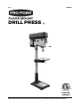
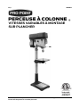
DRILL PRESS
FLOOR MOUNT

This page is intentionally left blank.

SPECIFICATIONS
Horsepower 1-1/2 HP
Drive Type Drive Belt
Voltage Rating 120V AC
Amperage Rating 13A
Phase 1
Frequency Rating 60 Hz
Number of Speeds Variable-speed
Speed Rating 600 to 2,400 RPM
Chuck Size 5/8 in.
Spindle Travel 6 in.
Spindle to Table 23-3/8 in.
Max. Spindle to Base 42-13/16 in.
Capacity 1 in.
Spindle Taper MT2
Table Size 14 x 14 in.
Number of T Slots 4
Table Slot Size 0.6 in.
Swing 17 in.
Column Diameter 3-1/8 in.
Base Size 20 x 13-13/16 in.
Dimensions (W X D X H) 14-3/16 x 30 x 69 in.
INTRODUCTION
The drill press is ideal for the home or shop. Using the correct drill bit, it
allows you to drill wood, cast iron, steel and aluminum with precision. It
features an adjustable speed.
SAFETY
WARNING! Read and understand all instructions before
using this tool. The operator must follow basic precautions
to reduce the risk of personal injury and/or damage to the
equipment.
V1.0 VARIABLE-SPEED FLOOR-MOUNT DRILL PRESS 9028002
Page 3 Assistance available at www.princessauto.com or 1-800-665-8685

HAZARD DEFINITIONS
Please familiarize yourself with the hazard notices found in this manual.
A notice is an alert that there is a possibility of property damage, injury
or death if certain instructions are not followed.
DANGER! This notice indicates an immediate and specific hazard that will
result in severe personal injury or death if the proper precautions are
not taken.
WARNING! This notice indicates a specific hazard or unsafe practice that could
result in a serious injury if the proper precautions are not taken.
CAUTION! This notice indicates a potentially hazardous situation that may
result in minor or moderate injury if proper practices are not taken.
NOTICE! This notice indicates that a specific hazard or unsafe practice will
result in equipment or property damage, but not personal injury.
WORK AREA
1. Operate in a safe work environment. Keep your work area clean,
well-lit and free of distractions. Place lights so you are not working
in a shadow.
2. Keep anyone not wearing the appropriate safety equipment away
from the work area.
3. Store unused tools properly in a dry, safe and secure location to
prevent rust, damage or misuse.
4. Do not install or use in the presence of flammable gases, dust or
liquids.
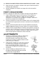
PERSONAL SAFETY
WARNING! Wear personal protective equipment approved by
the Canadian Standards Association (CSA) or American
National Standards Institute (ANSI).
PERSONAL PROTECTIVE EQUIPMENT
1. Always wear impact safety goggles that provide front and side
protection for the eyes. Eye protection equipment should comply
with CSA Z94.3-07 or ANSI Z87.1 standards based on the type of
work performed.
2. Wear protective clothing and gloves designed for the work
environment, materials and tools.
9028002 VARIABLE-SPEED FLOOR-MOUNT DRILL PRESS V1.0
Assistance available at www.princessauto.com or 1-800-665-8685 Page 4

a. Do not wear gloves when operating a tool that can snag the
material and pull the hand into the tool.
3. Wear the appropriate type of full-face shield in addition to safety
googles, as the work can create chips, abrasive or particulate
matter.
4. Wear the appropriate rated dust mask or respirator. Wear a NIOSH
approved respirator when working on materials that produce
hazardous fumes, dust or particulate matter.
PERSONAL PRECAUTIONS
Control the tool, personal movement and the work environment to avoid
personal injury or damage to tool.
1. Avoid wearing clothes or jewelry that can become entangled with
the moving parts of a tool. Keep long hair covered or bound.
2. Hold the workpiece securely against the fence. The drill's torque
will twist an unbraced workpiece out of your hand and may cause
an impact injury or the workpiece may be ejected and strike a
bystander or yourself.
3. Do not operate any tool when tired or under the influence of drugs,
alcohol or medications.
4. Do not overreach when operating a tool. Proper footing and
balance enables better control in unexpected situations.
SPECIFIC SAFETY
WARNING! DO NOT let comfort or familiarity with product
(gained from repeated use) replace strict adherence to the
tool safety rules. If you use this tool unsafely or incorrectly,
you can suffer serious personal injury.
NOTICE! Immediately switch the power off if the drill bit
becomes stuck or jammed. The tool’s torque may damage
the drill press mechanism and/or workpiece.
1. Use the correct tool for the job. This tool was designed for a
specific function. Do not modify or alter this tool or use it for an
unintended purpose.
2. A loose or mismatched bit may be ejected by the tool, causing an
injury to the user or a bystander. It may also fail to penetrate the
V1.0 VARIABLE-SPEED FLOOR-MOUNT DRILL PRESS 9028002
Page 5 Assistance available at www.princessauto.com or 1-800-665-8685

material as the point may move around under pressure, damaging
the workpiece.
a. Ensure the bit shank size matches the tool’s chuck or collet
size.
b. Tighten the chuck so the shank is tightly held with no room to
move.
3. Do not use the drill press as a router or try to elongate or enlarge
holes with the drill bit. The drill bit can break and can cause an
injury.
4. Never attempt to change the rotation direction while the switch is
ON. To do so, may damage the interlock feature built into the
switch. Be sure the switch is OFF and the motor has completely
stopped before changing the rotation direction.
5. Hardened gum and wood pitch on a drill bit slows the drill press
down and increases the potential for binding. Remove the drill bit
from the drill press, then clean it with hot water, kerosene or gum
and pitch remover. Never use gasoline. Allow to dry before using.
Discard the drill bit if the gum or pitch cannot be removed.
6. Clean the drill press's air vents often. The motor’s fan will draw
dust and other particulates into the tool. Excessive accumulation of
wood, plastic or metal particulates can create a fire or electrical
hazard.
7. Do not cool the drill bit with any liquid when hot. This can damage
the the drill bit by weakening the material, making the accessory
unsafe for use.
8. Inspect the tool components periodically. Repair or replace
damaged or worn components. Only use identical replacement
parts when servicing.
9. Do not install or use any drill bit that exceeds 175 mm in length or
extends 150 mm below the chuck jaws. The drill bit can suddenly
bend outward or break.
10. Do not use wire wheels, router bits, shaper cutters, circle cutters or
rotary planers on this drill press.
11. Remove adjusting keys and wrenches before using the tool. The
tool may eject an attached wrench or a key and cause an injury to
you or a bystander.
9028002 VARIABLE-SPEED FLOOR-MOUNT DRILL PRESS V1.0
Assistance available at www.princessauto.com or 1-800-665-8685 Page 6

POWER TOOL PRECAUTIONS
1. Do not use any power tool with a malfunctioning power switch or
control. A power tool that fails to respond to the controls is
dangerous and can cause an injury. A qualified technician must
repair and verify the power tool is operating correctly, before it can
be used.
2. Shut the power off and disconnect the drill press from the power
supply (if possible) before making any adjustments, changing
accessories, cleaning, servicing or when storing. Such preventive
safety measures reduce the risk of starting the tool accidentally.
3. Never force the drill press. Excessive pressure could break the
tool, resulting in damage to your workpiece or serious personal
injury. Excessive pressure is the cause if your tool runs smoothly
under no load, but roughly under load.
4. Check if the drill press's moving parts are misaligned or binding
before each use. Correct the issue before using the drill press to
avoid an injury or damage to the tool.
5. Only use accessories that are specifically designed for use with
the drill press. Ensure the drill bit is tightly installed.
6. The material and the motor housing can get very hot during
operation. Stop work until the drill press and the drill bit both cool
down to a safe temperature.
7. Do not cover the air vents. Proper cooling of the motor is
necessary to ensure normal life of the tool.
8. Make sure any adjustment mechanisms are secure before using
the tool
KICKBACK PRECAUTIONS
•The material can be ejected and inflict a serious injury on the user
or a bystander.
•Kickback can also damage the tool or workpiece.
Kickback can be avoided by taking proper precautions:
1. Maintain a firm grip on the material and position your body and
arms to allow you to resist a kickback. Kickback can propel the
material in the direction of the drill press's rotation.
V1.0 VARIABLE-SPEED FLOOR-MOUNT DRILL PRESS 9028002
Page 7 Assistance available at www.princessauto.com or 1-800-665-8685

a. Use a clamp to hold the material if the tool includes a
clamping system.
2. Use special care when working on corners, sharp edges or flexible
material. The workpiece has a tendency to snag the drill bit.
3. Only use the drill bit designed for the tool.
4. Always make sure the work surface is free from nails and other
foreign objects. Striking a nail can cause the drill bit to jump and
damage the drill bit.
ELECTRICAL SAFETY
WARNING! Do not touch or handle a live tool with any part
of your body that is wet or damp. Wet skin reduces
resistance to electrical current, increasing the danger of a
serious or fatal shock.
WARNING! To reduce risk of electric shock, be certain that
the plug is connected to a properly grounded receptacle.
1. Do not alter any parts of the tool or accessories. All parts and
accessories are designed with built-in safety features that may be
compromised if altered.
2. Protect yourself against electric shocks when working on electrical
equipment. Avoid body contact with grounded surfaces. There is
an increased chance of electrical shock if your body is grounded.
3. Do not expose the drill press to rain, snow, frost or any other damp
or wet conditions. Water entering a tool will increase the risk of
electric shock.
4. Do not disconnect the power cord in place of using the power
switch. This will prevent an accidental start-up when the power
cord is plugged into the power supply.
5. In the event of a power failure, turn off or unplug the machine as
soon as the power is interrupted. The possibility of accidental
injury could occur if the power returns and the unit is not switched
off.
6. Make certain the power source conforms to requirements of your
equipment (see Specifications).
7. This tool is only for use on 120 V (single phase) and is equipped
with a three-prong grounded power supply cord and plug. Check
9028002 VARIABLE-SPEED FLOOR-MOUNT DRILL PRESS V1.0
Assistance available at www.princessauto.com or 1-800-665-8685 Page 8

with a qualified electrician if you are in doubt as to whether the
outlet is properly grounded. If the tool should electronically
malfunction or break down, grounding provides a low resistance
path to carry electricity away from the user.
a. Never remove the grounding prong or modify the plug in any
way, as this will render the tool unsafe.
b. Do not use any adapter plugs.
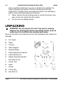
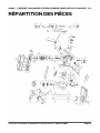
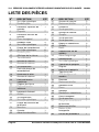
UNPACKING
WARNING! Do not operate the tool if any part is missing.
Replace the missing part before operating. Failure to do so
could result in a malfunction and personal injury.
Remove the parts and accessories from the packaging and inspect for
damage.
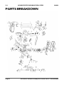
A. Drill Head
B. Table
C. Column
D. Table Support
E. Pedestal Base
F. Table Adjustment Handle
G. Feed Handles (3)
H. Speed Adjusting Handle
I. Hex Wrench (3)
J. Chuck Tool
K. Arbor
L. Chuck
M. Chuck Key
N. Hex Bolt (4)
Fig. 1
V1.0 VARIABLE-SPEED FLOOR-MOUNT DRILL PRESS 9028002
Page 9 Assistance available at www.princessauto.com or 1-800-665-8685

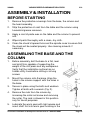
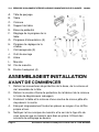
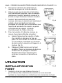
ASSEMBLY & INSTALLATION
BEFORE STARTING
1. Remove the protective coverings from the base, the column and
the head assembly.
2. Strip the protective oil coat from the table and the column using
household grease removers.
3. Apply a coat of paste wax on the table and the column to prevent
rust.
4. Wipe all parts thoroughly with a clean, dry cloth.
5. Clean the chuck’s tapered hole and the spindle nose to ensure that
the chuck will be seated properly. Use cleaning solvents if
necessary.
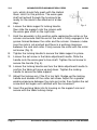
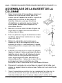
ASSEMBLING THE BASE AND THE
COLUMN
1. Before assembly, bolt the base to a flat, level
and solid floor capable of supporting the
weight of the drill press and any workpieces.
Verify that the installation surface has no
hidden utility lines before drilling or driving
screws.
2. Mount the column onto the base. Align the
holes in the column support with the holes in
the base.
3. Secure in place using the bolts and washers.
Tighten all bolts with a wrench (Fig. 2).
4. Remove the rack from the column by
loosening the collar set screw and removing
the collar. The rack is stowed in this position
only for transit purposes.
5. Lubricate the worm gear with light grease and
insert shaft first into worm gear housing in the
Fig. 2
Fig. 3
9028002 VARIABLE-SPEED FLOOR-MOUNT DRILL PRESS V1.0
Assistance available at www.princessauto.com or 1-800-665-8685 Page 10

arm, which should fully mesh with the Helical
Gear. Hold it in this position. The worm gear
shaft will extend through the housing to be
ready for the crank to be attached in a later
step.
6. Loosen the table support's locking handle,
then slide the support onto the column with
the worm gear shaft on the right side.
7. Hold the assembly in this position while replacing the collar on the
column and ensure that the end of the rack is firmly engaged in the
groove formed between the collar and the column. However, make
sure the rack is not pinched and there is a working clearance
between the rack and collar. Firmly secure the collar with the collar
set screw (Fig. 3).
8. Tighten the locking handle to secure the table support in place.
9. Loosen the set screw in the table adjustment handle. Slide the
handle onto the worm gear's drive shaft. Tighten the set screw to
secure the handle (Fig. 4).
10. Loosen the locking handle and turn the table adjustment handle to
confirm the table will move up and down. Tighten the locking
handle to secure the table support.
11. Adjust the locking arm if the fit is too tight. Nudge up the locking
handle and slacken off the collar set screw. Adjust for a greater
working clearance between the rack and collar, then tighten the set
screw and test again until satisfied with the movement.
12. Insert the working table into its housing on the support arm and
secure with the table locking clamp.
Fig. 4
V1.0 VARIABLE-SPEED FLOOR-MOUNT DRILL PRESS 9028002
Page 11 Assistance available at www.princessauto.com or 1-800-665-8685

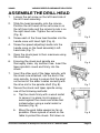
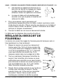
ASSEMBLE THE DRILL HEAD
1. Loosen the set screw on the left-hand side of
the drill head assembly.
2. Slide the head assembly onto the column.
Position the drill head so the set screw is on
the left-hand side and the column's rack is on
the right-hand side. Tighten the set screw
(Fig. 5).
3. Screw each of the three feed handles into the
handle case until hand-tight (Fig. 6).
4. Screw the speed adjusting handle into the
handle case on the head assembly's left-
hand side (Fig. 7).
5. Open the chuck jaws to their maximum using
the chuck key.
6. Ensuring the chuck and spindle are
thoroughly clean, dry and burr free. Insert the
taper spindle's round end firmly into the
chuck.
7. Insert the other end of the taper spindle, with
the chuck now attached, into the end of the
main spindle, turning to ensure that the point
on the end of the arbor locates correctly with
the drive slot in the spindle shaft (Fig. 8).
8. Secure the chuck and taper spindle using
one of the following methods:
a. Tap the chuck firmly with a wood mallet
to secure it in place. Hold a piece of
wood against the chuck and strike that
instead when using a metal mallet or
hammer (Fig. 9).
b. Move the work table upward as far as
possible. Place a piece of wood on the
table to protect the chuck. Pull down on
Fig. 5
Fig. 6
Fig. 7
Fig. 8
9028002 VARIABLE-SPEED FLOOR-MOUNT DRILL PRESS V1.0
Assistance available at www.princessauto.com or 1-800-665-8685 Page 12

the feed handles to press the spindle
and chuck into place.
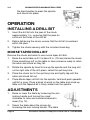
OPERATION
INSTALLING A DRILL BIT
1. Insert the drill bit into the jaws of the chuck
approximately 1 in., ensuring that the jaws do
not touch the flutes of the drill bit.
2. Before tightening the chuck, ensure that the drill bit is centered
within the jaws.
3. Tighten the chuck securely with the included chuck key.
MORSE TAPER DRILL BIT
Remove the chuck and arbor to use morse taper drill bits.
1. Raise the work table until it is about 3 in. (75 mm) below the chuck.
Place something soft on the table or have someone ready to catch
the arbor and chuck as they fall.
2. Rotate the spindle by hand to line up the spindle and the long slot
on the right side of the drill press, called the quill key hole.
3. Place the chuck tool in the quill key hole and lightly tap until the
arbor and chuck fall out.
4. Place Morse taper drill bit into the spindle, twist and push upwards
until bit is snug. Place a block of wood on the table and crank up
table until the tapered bit is firmly seated into the spindle.
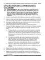
ADJUSTMENTS
1. Raise or lower the table by loosening the arm
locking handle and turning the crank:
clockwise to raise and counterclockwise to
lower (Fig. 10).
2. Swivel the table about the column by
loosening the arm locking handle. The table
Fig. 9
V1.0 VARIABLE-SPEED FLOOR-MOUNT DRILL PRESS 9028002
Page 13 Assistance available at www.princessauto.com or 1-800-665-8685
Fig. 10

assembly arm and rack move as one around
the column.
3. Tilt the table by loosening the bevel table
locking screw, removing the alignment pin
and tilting to the required angle (Fig. 11).
a. A scale is provided on the arm measured
in degrees to assist in setting the
required angle. For all normal operations
the table should be set at 0° (Fig. 12).
b. When the table is angled/tilted, ensure
the workpiece is clamped to the table.
4. To ensure that the drill is entirely
perpendicular to the table, insert a piece of
straight round bar in the chuck, place a
square on the table and bring it up to the
round bar. Adjust the table tilt if necessary so
that the table is correctly aligned.
5. Turn the table about its axis by loosening the clamp.
The table is capable of moving in four directions.
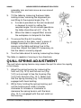
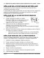
QUILL SPRING ADJUSTMENT
The quill return spring tension may cause the quill to return too rapidly
or too slowly.
1. Adjust the spring tension by loosening the
front nut (Fig. 14-3) and the rear nut (Fig.
14-2) only enough to free the housing (Fig.
14-4) from the boss (Fig. 14-1). Make sure
that the spring housing (Fig. 14-5) remains
engaged with head casting.
2. While firmly holding the spring housing, pull
out the housing and rotate it counter-
clockwise to increase or clockwise to
decrease the spring tension until the boss
(Fig. 14-1) is engaged with the next notch on
the housing.
Fig. 11
Fig. 12
Fig. 13
9028002 VARIABLE-SPEED FLOOR-MOUNT DRILL PRESS V1.0
Assistance available at www.princessauto.com or 1-800-665-8685 Page 14

3. Tighten the rear nut nut until it contacts the
spring housing. Then back the nut out 1/4
turn from the spring housing. Tighten the front
nut against the rear nut to hold the housing in
place.
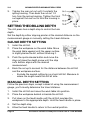
SETTING THE DRILLING DEPTH
The drill press has a depth stop to control the hole
depth.
Set the depth by either aligning pointer at the desired distance on the
measurement gauge or manually setting the travel distance.
GAUGE DEPTH SETTING
1. Install the drill bit.
2. Place the workpiece on the work table. Move
the work table upward until the upper surface
is slightly below the bit, without touching it.
3. Push the quick release button and move the
stop nut down the depth screw until the stop
nut's bottom aligns with the desired
measurement.
4. Back the nut up to account for the distance between the drill bit
and the workpiece surface.
• Exclude the angled cutting lip on a twist drill bit. Measure to
where the angle meets the drill bit side.
MANUAL DEPTH SETTING
Follow the previous steps, except instead of using the measurement
gauge, you'll visually determine the travel distance.
1. Install the drill bit and move the work table into position.
2. Place the workpiece behind or beside the drill bit.
3. Pull down on the feed handle until the drill bit overlaps the
workpiece to the appropriate depth. Hold the feed handle in place.
4. Set the depth stop.
5. Allow the feed handle to return to the neutral position.
Fig. 14
Fig. 15
V1.0 VARIABLE-SPEED FLOOR-MOUNT DRILL PRESS 9028002
Page 15 Assistance available at www.princessauto.com or 1-800-665-8685

6. The depth is set.
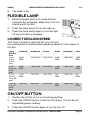
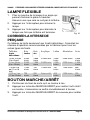
FLEXIBLE LAMP
1. Bend the lamp's shaft to an angle that will
illuminate the workpiece. Make sure it will not
interfere with the task.
2. Press the lamp switch to turn the light on.
3. Press the lamp switch again to turn the light
off once the task is complete.
CORRECT DRILLING SPEED
This chart is limited to twist drill bits only. Consult
the manufacturer's recommended operating speed for other types of
drill bits.
Twist
Drill Bit
Size
Softwood Hardwood Acrylic Brass Aluminum Steel
1/8 to
3/16 in.
(3 to 5
mm)
3,000
RPM
3,000 RPM 2,500 RPM 3,000
RPM
3,000 RPM 3,000
RPM
1/4 to
3/8 in. (6
to 10
mm)
3,000
RPM
1,500 RPM 2,000 RPM 1,200
RPM
2,500 RPM 1,000
RPM
7/16 to
5/18 in.
(11 to 16
mm)
1,500
RPM
750 RPM 1,500 RPM 750
RPM
1,500 RPM 600
RPM
11/16 to
1 in. (17
to 25
mm)
750 RPM 500 RPM Inadvisable 400
RPM
1,000 RPM 250
RPM
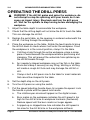
ON/OFF BUTTON
1. Position the drill bit so it is not touching anything.
2. Press the ON/OFF button to start the drill press. The drill bit will
immediately begin rotating.
3. Press the ON/OFF button again to turn the tool off.
Fig. 16
9028002 VARIABLE-SPEED FLOOR-MOUNT DRILL PRESS V1.0
Assistance available at www.princessauto.com or 1-800-665-8685 Page 16

OPERATING THE DRILL PRESS
WARNING! If the drill bit grabs and spins the workpiece, do
not attempt to stop the spinning with your hands, as it can
cause an impact injury. Step back and turn the drill press
off. Wait for the spindle to stop turning before dislodging the
workpiece.
1. Adjust the table depth to accomodate the workpiece.
2. Check that the drilling depth will not allow the bit to touch the table.
This can damage the drill bit.
3. Realign the work table, so the opening is centered underneath the
drill bit, if drilling through the workpiece.
4. Place the workpiece on the table. Rotate the feed handle to bring
the drill bit down to check where it will enter the workpiece. Once
the workpiece is in the correct position, clamp it to the table.
a. If drilling a hole through the entire workpiece, place a scrap
piece of wood beneath the workpiece before positioning and
clamping. This will prevent the underside from splintering as
the drill bit breaks through.
b. An irregularly shaped workpiece may not lay flat on the table.
Block and clamp it securely as any tilting, twisting or shifting
will create a rough drill hole and may damage the drill bit or
drill.
c. Clamp or bolt a drill press vise to the table for small materials
that cannot be clamped to the table.
5. Set the depth stop on the drill press.
6. Turn the drill press on using the switch.
7. Pull the speed adjusting handle down to increase the speed. Lock
the handle in place with the speed lock handle
a. The rotations-per-minute will appear on the digital screen.
b. Burn marks on the workpiece indicates the drill speed is too
high for the drill bit size or workpiece hardness (hardwood).
Reduce speed until the burn marks no longer appear.
c. A ripped-up or chipped bore hole indicates the drill speed is
too slow for the drill bit size or the workpiece softness
V1.0 VARIABLE-SPEED FLOOR-MOUNT DRILL PRESS 9028002
Page 17 Assistance available at www.princessauto.com or 1-800-665-8685

(softwood). Increase the drill speed until the bore hole is
smooth with clean edges.
8. Pull down on the feed handle and slowly drill a hole into the
workpiece.
9. Once the desired depth is reached, slowly push the feed handle up
until the drill bit clears the workpiece.
10. Turn the drill off and wait for the drill bit to stop. Remove or
reposition the workpiece.
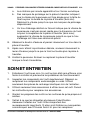
CARE & MAINTENANCE
1. Maintain the tool with care. A tool in good condition is efficient,
easier to control and will have fewer problems.
2. Inspect the tool components periodically. Repair or replace
damaged or worn components. Only use identical replacement
parts when servicing.
3. Only use accessories intended for use with this tool. Follow
instructions for changing accessories.
4. Keep the tool handles or gripping surfaces clean and dry.
5. Maintain the tool’s labels and name plates. These carry important
information. If unreadable or missing, contact Princess Auto Ltd.
for replacements.
6. Clear the vents of any dirt, dust and debris on a regular basis to
prevent the tool from overheating.
WARNING! Only qualified service personnel should repair
the tool. An improperly repaired tool may present a hazard
to the user and/or others.
DISPOSAL
Recycle a tool damaged beyond repair at the appropriate facility.
Contact your local municipality for a list of disposal facilities or by-laws
for electronic devices, batteries, oil or other toxic liquids.
9028002 VARIABLE-SPEED FLOOR-MOUNT DRILL PRESS V1.0
Assistance available at www.princessauto.com or 1-800-665-8685 Page 18

STORAGE
When not in use for an extended period, apply a thin coat of lubricant to
the steel parts to avoid rust. Remove the lubricant before using the tool
again.
1. Components should be kept dry, with machined surfaces lightly
oiled.
2. Always remove drill bits and store in a safe place.
3. Never store equipment in a wet/damp environment.
TROUBLESHOOTING
Visit a Princess Auto Ltd. location for a solution if the tool does not
function properly or parts are missing. If unable to do so, have a
qualified technician service the tool.
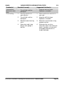
Problem(s) Possible Cause(s) Suggested Solution(s)
The drill press
will not start. 1. Supplied power is
interrupted.
2. On/Off switch is faulty.
3. Motor components are
defective.
4. Motor has overheated.
1. Check that power supply is
still available.
2. Replace faulty switch.
3. Have a qualified technician
service the tool.
4. Allow motor to cool before
attempting to use.
Motor starts
slow and
doesn't reach
operation
speed.
1. Motor is damaged.
2. Extension cord is too
long or wire gauge is
too thin.
1. Have a qualified technician
service the tool.
2. Eliminate the use of an
extension cord. If an extension
cord is needed, use one with
the proper diameter for its
length and load.
Tool is making
unusual
sounds.
1. The drill press's parts
may be rubbing or
binding.
2. Belt too loose (slipping)
or too tight (bearing
damage).
1. Check for obstructions or
misaligned tool components.
Lubricate, repair or replace the
components based on the
particular problem.
2. Properly tension belt.
V1.0 VARIABLE-SPEED FLOOR-MOUNT DRILL PRESS 9028002
Page 19 Assistance available at www.princessauto.com or 1-800-665-8685

Problem(s) Possible Cause(s) Suggested Solution(s)
Performance
decreases over
time.
• The drill bit is dull or
damaged
• Keep the drill bit sharp.
Replace as needed
Overheating 1. Forcing machine to
work too fast.
2. The drill bit is dull or
damaged
3. Blocked motor housing
vents.
4. Extension cord is too
long or wire gauge is
too thin.
1. Allow machine to work at its
own rate.
2. Keep the drill bit sharp.
Replace as needed
3. Blow dust out of motor using
compressed air.
4. Eliminate the use of an
extension cord. If an extension
cord is needed, use one with
the proper diameter for its
length and load.
9028002 VARIABLE-SPEED FLOOR-MOUNT DRILL PRESS V1.0
Assistance available at www.princessauto.com or 1-800-665-8685 Page 20
La page est en cours de chargement...
La page est en cours de chargement...
La page est en cours de chargement...
La page est en cours de chargement...
La page est en cours de chargement...
La page est en cours de chargement...
La page est en cours de chargement...
La page est en cours de chargement...
La page est en cours de chargement...
La page est en cours de chargement...
La page est en cours de chargement...
La page est en cours de chargement...
La page est en cours de chargement...
La page est en cours de chargement...
La page est en cours de chargement...
La page est en cours de chargement...
La page est en cours de chargement...
La page est en cours de chargement...
La page est en cours de chargement...
La page est en cours de chargement...
La page est en cours de chargement...
La page est en cours de chargement...
La page est en cours de chargement...
La page est en cours de chargement...
La page est en cours de chargement...
La page est en cours de chargement...
La page est en cours de chargement...
La page est en cours de chargement...
La page est en cours de chargement...
La page est en cours de chargement...
La page est en cours de chargement...
La page est en cours de chargement...
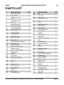
-
 1
1
-
 2
2
-
 3
3
-
 4
4
-
 5
5
-
 6
6
-
 7
7
-
 8
8
-
 9
9
-
 10
10
-
 11
11
-
 12
12
-
 13
13
-
 14
14
-
 15
15
-
 16
16
-
 17
17
-
 18
18
-
 19
19
-
 20
20
-
 21
21
-
 22
22
-
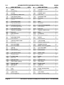 23
23
-
 24
24
-
 25
25
-
 26
26
-
 27
27
-
 28
28
-
 29
29
-
 30
30
-
 31
31
-
 32
32
-
 33
33
-
 34
34
-
 35
35
-
 36
36
-
 37
37
-
 38
38
-
 39
39
-
 40
40
-
 41
41
-
 42
42
-
 43
43
-
 44
44
-
 45
45
-
 46
46
-
 47
47
-
 48
48
-
 49
49
-
 50
50
-
 51
51
-
 52
52


PROPOINT 9028002 Le manuel du propriétaire
- Taper
- Le manuel du propriétaire
dans d''autres langues
- English: PROPOINT 9028002 Owner's manual
Documents connexes
Autres documents
-
Powerfist 9103219 Le manuel du propriétaire
-
-
-
-
-
-
Power Fist 8654345 Le manuel du propriétaire
-
-
-