
cod. 3541F061 - 01/2016
COMBI WALL MOUNTED GAS BOILER
INSTALLATION, OPERATION & MAINTENANCE MANUAL
CHAUDIÈRE À GAZ MURALE COMBI
MANUEL D’INSTALLATION, D’UTILISATION ET D’ENTRETIEN
Model
Modèle
CCB-150
2201 Dwyer Avenue, Utica NY 13501
web site: www.ecrinternational.com
Réf. 240010632, Rév. D [20/01/2016]

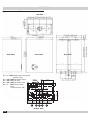
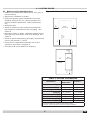
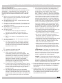
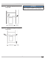
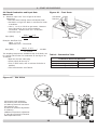
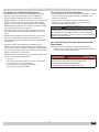
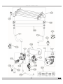
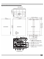
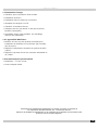
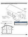
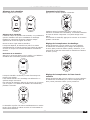
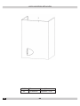
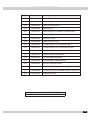
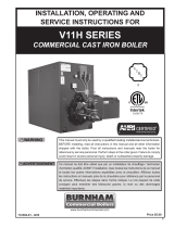
Figure 1 - Overall Dimensions
Rear View
Bottom View
1 = 1“ MPT Supply Water to Heating
System (Out)
2 = 3/4” MPT Tap Water Outlet
3 = 3/4” FPT Gas Inlet
4 = 3/4” MPT Tap Water Inlet
5 = 1” MPT Return Water
From
Heating System (IN)
2
DIMENSIONS
Top View
Side View Front View
EN
(85 mm) (76 mm) (55 mm) (50 mm) (80 mm) (104 mm)
(64 mm)
(196 mm)(35
mm)
(Ø22.5 mm)
Ø0 57/64 in
13/8 in 7 23/32 in
2 33/64 in
3 11/32 in 2 63/64 in
2 11/64 in 1 31/32 in
3 5/32 in 4 3/32 in
(179 mm)
7
3/64 in
(127 mm)
5
in
5431 2
2
EN

TABLE OF CONTENTS
3
1 - Introduction ................................................................................................................... 4
2 - Important Safety Information
........................................................................................... 5
3 - General View And Main Components
................................................................................. 6
4 - Locating Boiler
............................................................................................................... 9
5 - Hydronic Piping
............................................................................................................ 11
6 - Combustion Air And Vent Piping - Category I (Chimney Vent)
............................................ 15
6 - Combustion Air And Vent Piping Of Direct Vent And Category III
......................................... 17
6 - Combustion Air And Ventilation
....................................................................................... 19
7 - Gas Supply Piping
......................................................................................................... 22
8 - Electrical Connections
................................................................................................... 23
9 - Start Up Procedure
....................................................................................................... 24
10 - Operating Instructions
................................................................................................. 26
11 - General Maintenance And Cleaning
................................................................................ 33
12 - Ratings And Capacities
................................................................................................ 34
13 - Trouble Shooting......................................................................................................... 37
Wiring diagram
................................................................................................................. 38
Repair Parts List
................................................................................................................ 39
EN
3
EN

1 - INTRODUCTION
1.1 Designated Use
• Hot water heating boiler.
• Indoor installation.
• Closet or alcove installation.
• Catagory I or III Venting.
• Direct vent boiler.
• )RUXVHZLWKQDWXUDOJDVRUOLTXH¿HGSHWUROHXPJDVHV
(LP/propane).
• Directly heat potable water. Indirect heating is
acceptable.
1.2 The unit MUST NOT:
• Heat water with non-hydronic heating system chemicals
p r e s e n t ( e x a m p l e , s w i m m i n g p o o l w a t e r ) .
• Exceed 185°F (85°C) system design temperature.
• Exceed MWAP 43.5 PSIG
1.3 Operational Features
• Modulating: 3-1 turn down.
• Integral Dual Limit.
,QIRUPDWLRQDQGVSHFL¿FDWLRQVRXWOLQHGLQWKLVPDQXDOLQHIIHFWDWWKH
WLPHRISULQWLQJRIWKLVPDQXDOECR International, Inc.UHVHUYHVWKHULJKWWR
GLVFRQWLQXHFKDQJHVSHFL¿FDWLRQVRUV\VWHPGHVLJQDWDQ\WLPHZLWKRXW
QRWLFHDQGZLWKRXWLQFXUULQJDQ\REOLJDWLRQZKDWVRHYHU
4
EN
4
EN

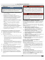
2 - IMPORTANT SAFETY INFORMATION
NOTICE
Used to address practices not related to
personal injury.
CAUTION
Indicates a hazardous situation which, if not
avoided, could result in minor or moderate
injury.
!
WARNING
Indicates a hazardous situation which, if not
avoided, could result in death or serious injury.
!
DANGER
Indicates a hazardous situation which, if not
avoided, WILL result in death or serious injury.
!
This is the safety alert symbol. Symbol alerts you to
potential personal injury hazards. Obey all safety messages
following this symbol to avoid possible injury or death.
2.2 Become familiar with symbols identifying
potential hazards.
WARNING
Fire, explosion, asphyxiation and electrical
shock hazard. Improper installation could
result in death or serious injury. Read this
manual and understand all requirements
before beginning installation.
!
2.3 Installation shall conform to requirements of
authority having jurisdiction or in absence of such
requirements:
•
United States
• National Fuel Gas Code, ANSI Z223.1/NFPA 54
.
• National Electrical Code, NFPA 70.
• Canada
• Natural Gas and Propane Installation Code,
CAN/CSA B149.1.
• Canadian Electrical Code, Part I, Safety Standard
for Electrical Installations, CSA C22.1
2.4 Requirements for Commonwealth of
Massachusetts:
Boiler installation must conform to Commonwealth of
Massachusetts code 248 CMR which includes but is not
limited to:
• ,QVWDOODWLRQE\OLFHQVHGSOXPEHURUJDV¿WWHU
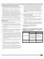
2.5 CSD-1 Requirements:
Where required by the authority having jurisdiction, the
installation must conform to the Standard for Controls and
Safety Devices for Automatically Fired Boilers, ANSI/ASME
CSD1.
2.1 General
%RLOHULQVWDOODWLRQVKDOOEHFRPSOHWHGE\TXDOL¿HGDJHQF\
See glossary for additional information.
5
EN
5
EN

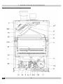
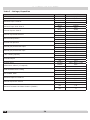
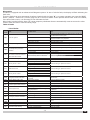
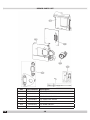
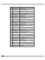
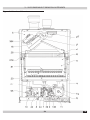
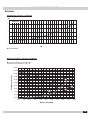
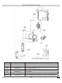
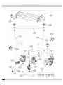
Figure 2 - Component Listing
6
3 - GENERAL VIEW AND MAIN COMPONENTS
EN
6
EN

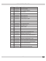
Item
1XPEHU
Description
5 Sealed Chamber
7 Gas Inlet
8 Domestic Hot Water (DHW) Outlet
9 Domestic Cold Water (DHW) Inlet
10 Supply System
11 System Return
16 Modulating Fan
19 Combustion Chamber
20 Burner Assembly
26 Combustion Chamber Insulation
27 Copper Heat Exchanger
28 Exhaust Manifold
29 Exhaust Outlet Manifold
32 Heating circulating pump
36 Automatic Air Vent
39 DHW Flow Regulator
42 DHW Temperature Sensor
44 Gas Valve
81 Ignition and Detection Electrode
95 3 Way Diverter Valve
114 Water Pressure Switch
136 Flow Meter
194 DHW Flate Plate Heat Exchanger
278 Double Sensor - High Limit NTC
297 Air Pressure Switch
364 Condensate Union
Unit Weight - 74 LBS (33.5 kg)
Shipping Weight - ~ 78 LBS (35.5 kg)
7
3 - GENERAL VIEW AND MAIN COMPONENTS
EN
7
EN

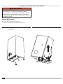
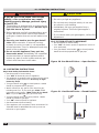
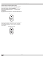
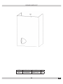
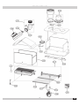
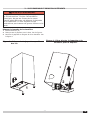
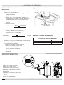
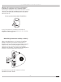
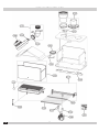
Remove Boiler Jacket
1.
Unscrew screws (A).
2.
3.
5DLVH-DFNHWXSDQGRIIERLOHU6HH¿JXUH
1
3
2
A
A
Figure 3 -DFNHW5HPRYDO6FUHZ
Locations
Figure 4 - Pivot Jacket and Raise to Remove
WARNING
Fire, explosion, asphyxiation and electrical
shock hazard. Disconnect electrical power
supply and turn off gas at shutoff valve before
attemting to remove boiler jacket. Failure to
follow these instructions could result in death
or serious injury.
!
8
3 - GENERAL VIEW AND MAIN COMPONENTS
EN
Pivot jacket upwards. See fi gure 4
8
EN

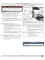
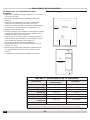
Figure 5 - Boiler Clearances
9
4 - LOCATING BOILER
4.1 Boiler Location Considerations
• Ambient room temperature always above 32°F (0°C) to
prevent freezing.
• Approved for installation in closets.
• Protect gas ignition system components from water
(dripping, spraying, rain, etc.) during operation and
service (circulator replacement, control replacement,
etc.).
• Wall mount only.
• Access to outdoors to meet minimum and maximum
pipe lengths for combustion air and vent piping. See
section 6.
• Drainage of water (or water - antifreeze solution) during
boiler service or from safety relief valve discharge. See
section 5.
• Access to system water piping, gas supply, and electrical
service. See sections 5, 7 and 8.
• Clearances to combustible materials and service
FOHDUDQFHV6HH7DEOHDQG¿JXUH
• The boiler shall not be installed on carpeting.
A
D
FLOOR
F
TABLE 1: BOILER CLEARANCES
Dimension
&RPEXVWLEOH
Materials
(1)
Service
(1)(2)
Top (A)
16” (41cm) 16" (41cm)
Left Side (B)
0" (0 cm) 1” (3 cm)
5LJKW6LGH&
0" (0 cm) 1” (3 cm)
Front (D)
0" (0 cm) 1" 3 cm)
Back (E)
0" (0 cm) 0” (0 cm)
Bottom (F)
0" (0 cm) 12" (30 cm)
&RPEXVWLRQ$LUSLSLQJ
0" (0 cm) 3/8" (1 cm)
Vent piping
6" (15 cm) 6" (15 cm)
(1)
Required distances measured from boiler jacket.
(2)
Service, proper operation clearance recommendation.
F
Boiler
(Side View)
Boiler
(Front View)
F
BC
Front
EN
9
EN

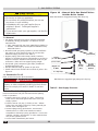
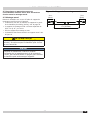
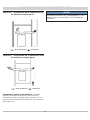
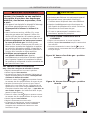
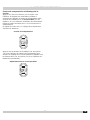
Figure 6 - Wall Mounting Bracket
10
4 - LOCATING BOILER
4.2 3UHSLSHVXSSO\DQGUHWXUQZDWHUFRQQHFWLRQV
ZLWKIDFWRU\¿WWLQJVEHIRUHZDOOPRXQWLQJ
4.3 Wall Mounting
Mount boiler on wall using wall mounting bracket included
with unit.
• Structure must be capable of supporting boiler weight
plus 60 lbs (28 kg). See page 7.
• Wall mount bracket has 2 slots, spaced at
9¼”
(23.5cm) on center
.
• Attach wall mount bracket level on wall.
• %RLOHUPXVWHQJDJHZLWKZDOOPRXQWEUDFNHW6HH¿JXUH
CAUTION
Boiler weight exceeds 75 pounds (34 kg). Do not
lift boiler onto wall without assistance.
!
NOTICE
Lift boiler using chassis. Using front jacket, vent
SLSLQJZDWHURUJDV¿WWLQJVWROLIWERLOHUPD\FDXVH
damage to the boiler.
EN
2
23
/64"
9
1
/4" (23.5cm)
(6cm)
2
23
/64"
(6cm)
10
EN

11
5 - HYDRONIC PIPING
5.1 General
• Install piping in accordance with authority having jurisdiction.
NOTICE
8VHWZRZUHQFKHVZKHQWLJKWHQLQJDQG¿WWLQJ
SLSHWRERLOHUVWKUHDGHG¿WWLQJV%RLOHUVLQWHUQDO
piping can be damaged if subjected to excessive
torque.
• Support system piping and safety relief valve discharge
piping. Boiler's internal piping and wall mount bracket
can be damaged if subjected to excessive weight.
• Size central heating pump (and domestic hot water
pump, if used) for system requirements only. Internal
heat exchanger pump compensates for pressure drop
through boiler internal piping and heat exchanger.
• 7KRURXJKO\FOHDQDQGÀXVKV\VWHPEHIRUHFRQQHFWLQJWRERLOHU
• If oil is present in system water, use approved detergent to
wash system.
• Flush system to remove any solid objects such as metal chips,
¿EHUVRU7HÀRQWDSHHWF
:DWHU6\VWHP&KDUDFWHULVWLFV
• Water in the heating system must have protection of
metallic materials against corrosion.
• Filling water and subsequent replenishing, must be
clear, with hardness under 150 ppm CaCO3,
A. treated with approved conditioning chemicals
to ensure prevention of corrosion and attack on
metals and plastics, that gases do not form,
B. and bacterial or microbial masses do not proliferate
in low temperature systems.
• Hardness exceeding 150 ppm CaCO3, appropriate water
softening treatment and/or use of suitable anti-fouling
agents must be provided.
Water contained in the system must be checked at least
yearly and have:
A. pH above 7 and under 8.5 (under 8 with presence
of components in aluminum or light alloys),
B. iron content (Fe) less than 0.5 mg/l,
C. copper content (Cu) less than 0.1 mg/l,
D. total content of chlorides, nitrates and sulfates less
than 50mg/l,
E. must contain conditioning chemicals in
FRQFHQWUDWLRQVXI¿FLHQWWRSURWHFWV\VWHPIRUD
year.
There must be no microbial or bacterial loads in low
temperature systems.
&RQGLWLRQHUVDGGLWLYHVLQKLELWRUVDQGDQWLIUHH]HÀXLGVFDQ
be used only if manufacturer guarantees they are suitable
for use in heating systems and they do not cause damage
to heat exchanger or other components and/or materials of
boiler and system.
8VHRIJHQHULFFKHPLFDOVQRWVSHFL¿FDOO\VXLWDEOHIRUXVHLQ
heating systems and/or incompatible with boiler materials
and system is forbidden.
Conditioning chemicals must ensure complete deoxygenation
RIZDWHUDQGFRQWDLQVSHFL¿FSURWHFWLYHDJHQWVIRU\HOORZ
metals (copper and its alloys), anti-fouling agents for
limescale at least up to 150 ppm CaCO3, pH neutral
VWDELOL]HUVDQGLQORZWHPSHUDWXUHV\VWHPVVSHFL¿FELRFLGHV
for use in heating systems.
,QV\VWHPVZLWKFRQWLQXRXVLQWDNHRIR[\JHQHJÀRRU
systems without anti-diffusion pipes, open expansion
vessels), or intermittent (e.g. in case of frequent
replenishing), a separator must be provided. Regarding
domestic hot water (DHW), no type of treatment which
could prevent its possible food use can be provided for.
WARNING
• Poison hazard. Ethylene glycol is toxic. Do not
use ethylene glycol.
• Never use automotive or standard glycol antifreeze,
even ethylene glycol made for hydronic systems.
• Ethylene glycol can attack gaskets and seals used
in hydronic systems.
• Use only inhibited propylene glycol solutions
FHUWL¿HGE\ÀXLGPDQXIDFWXUHUDVDFFHSWDEOHIRU
use with closed water heating system.
• 7KRURXJKO\FOHDQDQGÀXVKDQ\V\VWHPWKDWXVHG
glycol before installing new Boiler.
• 3URYLGHXVHUZLWK6DIHW\'DWD6KHHW6'6RQÀXLG
used.
NOTICE
Do not expose boiler to freezing temperatures.
5.3 Special Conditions
• System piping exposed to freezing conditions: Use
LQKLELWHGSURS\OHQHJO\FROVROXWLRQVFHUWL¿HGE\ÀXLG
manufacturer for use with closed water heating system.
Do not use automotive or ethylene glycol.
• Boiler used in connection with refrigeration system.
Install piping in parallel with boiler, with appropriate
valves to prevent chilled medium from entering boiler.
• System piping connected to heating coils located in air
handling unit exposed to refrigerated air circulation. Install
ÀRZFRQWUROYDOYHVRURWKHUDXWRPDWLFPHDQVWRSUHYHQW
gravity circulation of boiler water during cooling cycle
.
EN
!
11
EN

12
WARNING
Burn and Scald Hazard. Safety relief vlave
could discharge steam or hot water during
operation. Install discharge piping per these
instructions. Failure to do so could result in
death or serious injury.
!
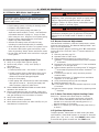
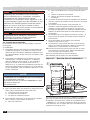
5.4 Safety Relief Valve
NOTICE
Boiler rated at 43.5 psig (.30MPa) maximum allowable
working pressure. Boiler provided with 30 psig
(.21MPa) safety relief valve.
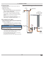
• ,QVWDOOVDIHW\UHOLHIYDOYHXVLQJSLSH¿WWLQJVSURYLGHGZLWK
ERLOHU6HH¿JXUH
• Install safety relief valve with spindle in vertical position.
• Do not install shutoff valve between boiler and safety
relief valve.
• Install discharge piping from safety relief valve. See
¿JXUH
• Use ¾” or larger pipe.
• Use pipe suitable for temperatures of 375°F (191°C)
or greater.
• Individual boiler discharge piping shall be independent
of other discharge piping.
• Size and arrange discharge piping to avoid reducing
safety relief valve relieving capacity below minimum
relief valve capacity stated on rating plate.
• Run pipe as short and straight as possible to location
protecting user from scalding and properly drain
piping.
• Install union, if used, close to safety relief valve outlet.
• Install elbow(s), if used, close to safety relief valve
outlet and downstream of union (if used).
• Terminate pipe with plain end (not threaded).
5 - HYDRONIC PIPING
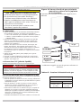
Figure 7 6DIHW\5HOLHI9DOYH$LU9HQW
9LHZHGIURPIURQWRIERLOHU
Check Local Codes
for Maximum
Distance to Floor
Safety Relief
Valve
Gas Shutoff
Valve
in Open
position
Figure 8 6DIHW\5HOLHI9DOYH'LVFKDUJH
Piping
EN
1” MPT
Coupling 1” NPT
Nipple 1” x 5”
Tee 1” x 1” x ¾”
Safety Relief
Valve
Street Elbow ¾”
12
EN

13
5 - HYDRONIC PIPING
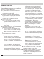
5.5 System Piping
• 6\VWHPVZLWKDXWRPDWLF¿OOYDOYHVUHTXLUHEDFNÀRZ
prevention device.
• Single boiler system.
Additional considerations:
• Boiler control is designed for single central heating
pump. Installer responsible for integration of
multiple central heating pumps.
• Boiler control allows domestic hot water
prioritization. Function could be lost if central
heating pump is not directly connected to control
system
• Refer to all local codes and jurisdictional
UHTXLUHPHQWVIRULQVWDOODWLRQRI¿HOGVXSSOLHGDQWL
scald valve(s), and DHW expansion tank.
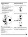
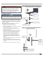
5.5A Low Water Cut Off (LWCO)
• Boiler installed above radiation level (or as required by
authority having jurisdiction) shall have low water cutoff
SURWHFWLRQ6HH¿JXUH
• Connect LWCO switch leads to terminals provided.
See Boiler Wiring Diagram. Provide power to LWCO
per manufacturer’s instructions.
NOTICE
Boiler transformer does not have adequate VA to power
accessories, including LWCO.
• /RZ:DWHU&XWRII/:&2SUREHORFDWLRQ6HH¿JXUH
9 for minimum probe height. Do not install shutoff
valve between boiler and LWCO probe.
• If using separate stand pipe, install air vent using
tee to avoid nuissance shutdowns.
• Arrange piping to prevent water dripping onto boiler.
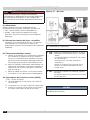
Figure 9 /:&26XJJHVWHG3UREH/RFDWLRQ
Air Vent
LWCO
To
Supply
Gas
Supply
Minimum
acceptable height
for LWCO control
Safety Relief
Valve
Return
Water
Pipe
to Drain
12” [304.8mm]
Maximum Distance
13
EN

14
5 - HYDRONIC PIPING
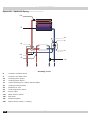
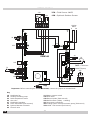
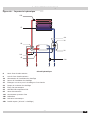
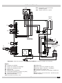
Figure 10 +\GURQLF3LSLQJ
3OXPELQJFLUFXLW
8 Domestic Hot Water Outlet
9 Domestic Cold Water Inlet
10 Heating System Supply
11 Heating System Return
27 Copper Exchanger For Heating And Hot Water
32 Heating Circulating Pump
36 Automatic Air Vent
42 DHW Temperature Sensor
95 Diverter Valve
114 Water Pressure Switch
136 Flow Meter
241 Automatic Bypass
278 Double Sensor (Safety + Heating)
EN
14
EN

15
6 - COMBUSTION AIR AND VENT PIPING - CATEGORY I (CHIMNEY VENT)
&KHFN<RXU&KLPQH\
Chimney must be clean, right size, properly constructed
and in GOOD CONDITION.
1.
Installation must conform to requirements of the
authority having jurisdiction or, in absence of such
requirements, to the National Fuel Gas Code, ANSI
Z223.1/NFPA 54 and/or Natural Gas and Propane
Installation Code, CAN/CSA B149.1.
2.
,QFUHDVHU¿WWLQJLVUHTXLUHGRQWKLVERLOHUIRU&DWHJRU\,
venting, and 4” is minimum permissible vent diameter.
This does not imply vent connector is intended to be 4”
diameter pipe. Vent connector shall be sized according
to appropriate venting tables in the National Fuel
Gas Code and may be required to be larger than 4”
diameter.
NOTICE
Boiler installation for chimney venting is not
FRPSOHWHXQOHVVLQFUHDVHU¿WWLQJLVORFDWHGDQG
secured.
3.
Venting into masonry chimney without liner, line
chimney from top to bottom with either:
A. Listed Type B vent pipe
B. /LVWHGÀH[LEOHYHQWOLQHU
C. Poured ceramic liner.
4.
Outside chimneys should not be used unless they are
(choose one of the following):
A. Enclosed in a chase
B. Lined with Type B vent pipe
C. 8VHOLVWHGÀH[LEOHYHQWOLQHU
D. 8VHFHUWL¿HGFKLPQH\OLQLQJV\VWHP
5.
Vent connector from boiler to chimney should run as
directly as possible with as few elbows as possible.
6.
Common venting shall not be allowed. Boiler and other
FHUWL¿HGDSSOLDQFHVFDQVKDUHVDPHFKLPQH\YHQW
Consult appropriate Vent Sizing Tables in National
)XHO*DV&RGHIRUVSHFL¿FUHTXLUHPHQWVRIPXOWLSOH
appliance venting.
7.
Boiler is only appliance connected to vent, Type B vent
pipe is recommended for vent connector.
8.
Slope pipe up from boiler to chimney not less than 1/4”
per foot (21mm/m).
9.
(QGRIYHQWSLSHPXVWEHÀXVKZLWKLQVLGHIDFHRI
FKLPQH\ÀXH8VHVHDOHGLQWKLPEOHIRUFKLPQH\
connection.
10.
Fasten sections of vent pipe with sheet metal screws to
make piping rigid. Use stovepipe wires to support pipe
from above.
11.
'RQRWFRQQHFWWR¿UHSODFHÀXH
12.
Do not install damper on this boiler.
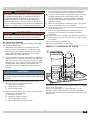
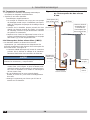
Figure 11 &RPEXVWLRQ$LU)LWWLQJ
3
3
+RUL]RQWDO9HQWLQJUHTXLUHV¿HOGVXSSOLHGDSSOLDQFHDGDSWHU
IRUWKHERLOHUÀXHRXWOHW
Boiler is provided with a 3” vent connection, 3” x 4”
LQFUHDVHUPXVWEH¿HOGVRXUFHGIRUFKLPQH\DSSOLFDWLRQ
This does not mean that the connection to the chimney will
always be 4”.
WARNING
Boiler and venting installations shall be performed
E\DTXDOL¿HGH[SHUWDQGLQDFFRUGDQFHZLWKWKH
appropriate manual. Installing or venting boiler
or other gas appliance with improper methods or
materials may result in serious injury or death due
WR¿UHRUWRDVSK\[LDWLRQIURPSRLVRQRXVJDVHVVXFK
as carbon monoxide with is odorless and invisible.
!
WARNING
Do not connect boiler to any portion of mechanical
draft system operating under positive pressure.
!
EN
15
EN

16
6 - COMBUSTION AIR AND VENT PIPING- CATEGORY I (CHIMNEY VENT)
6.2 Minimum Vent Pipe Clearance
• Use Type B vent pipe through crawl space. Where vent
pipe passes through combustible wall or partition, use
ventilated metal thimble. Thimble should be 4 inches
larger in diameter than vent pipe.
• Boiler installed with single wall vent, must have 6”
clearance between its surface and any combustible
PDWHULDO1HZ7\SH%JDVYHQWRUÀH[LEOHOLQHUPXVWEH
installed in accordance with instructions furnished with
YHQW0DLQWDLQFOHDUDQFHVDVVSHFL¿HGIRUYHQWSLSH
• 9HULI\YHQWSLSHLV¿UHVWRSSHGZKHUHLWJRHVWKURXJK
ÀRRURUFHLOLQJ,WVKRXOGKDYHDSSURYHGYHQWFDSZLWK
clearances from roof. If clearances are less than shown,
have vent checked by local authorities. Figure 12, Page
20.
• Vent connectors serving appliances vented by natural
draft shall not be connected into any portion of
mechanical draft systems operating under positive
pressure.
6.3 Removing Existing Boiler From Common
9HQWLQJ6\VWHP
When an existing boiler is removed from a common
venting system, common venting system is likely to be
too large for proper venting of the appliances remaining
connected to it.
1.
At the time of removal of an existing boiler, the
following steps shall be followed with each appliance
remaining connected to the common venting system
placed in operation, while the other appliance
remaining connected to the common venting system
are not in operation.
2.
Seal any unused openings in the common venting
system.
3.
Visually inspect the venting system for proper size and
horizontal pitch and determine there is no blockage or
UHVWULFWLRQOHDNDJHFRUURVLRQDQGRWKHUGH¿FLHQFLHV
which could cause an unsafe condition.
4.
Insofar as is practical, close all building doors and
windows and all doors between the space in which the
appliances remaining connected to the common venting
system are located and other spaces of the building.
Turn on clothes dryers and any appliance not connected
to the common venting system. Turn on any exhaust
fans, such as range hoods and bathroom exhausts, so
they will operate at maximum speed. Do not operate a
VXPPHUH[KDXVWIDQ&ORVH¿UHSODFHGDPSHUV
5.
Place in operation the appliance being inspected. Follow
the lighting instructions. Adjust thermostat so appliance
will operate continuously.
6.
Test for spillage at the draft hood relief opening after
PLQXWHVRIPDLQEXUQHURSHUDWLRQ8VHÀDPHRID
match or candle, or smoke from a cigarette, cigar, or
pipe.
7.
After it has been determined that each appliance
remaining connected to the common venting system
properly vents when tested as outlined above, return
GRRUVZLQGRZVH[KDXVWIDQV¿UHSODFHGDPSHUVDQG
any other gas-burning appliance to their previous
conditions of use.
8.
Any improper operation of the common venting system
should be corrected so the installation conforms with
the National Fuel gas Code, ANSI Z223.1/NFPA 54,
and/or the Natural Gas and Propane Installation Code,
CAN/CSA B149.1. When re-sizing any portion of the
common venting system, the common venting system
should be re-sized to approach the minimum size
determined using the appropriate tables in Chapter 13
of the National Fuel Gas Code, ANSI Z223.1/NFPA 54,
and/or the Natural Gas and Propane Installation Code,
CAN/CSA B149.1.
9.
It is recommended that existing gas vents be checked
to be sure they meet local codes.
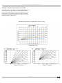
6.4 Modulating Fan
• Unit is equipped with an advanced combustion air, vent
ÀRZFRQWUROV\VWHPZLWKPRGXODWLQJIDQDQGSUHVVXUH
sensor.
• 8QLWDXWRPDWLFDOO\DGDSWVLWVRSHUDWLRQWRÀXHW\SH
and length, without requiring adjustments during
LQVWDOODWLRQRUXVHRIEDIÀHVLQFRPEXVWLRQFLUFXLW
• Unit consistantly and automatically regulates
FRPEXVWLRQDLUDQGYHQWÀRZDFFRUGLQJWRFKDQJHLQ
thermal load. Combustion and heat exchange occur in
RSWLPXPFRQGLWLRQV8QLW¶VWKHUPDOHI¿FLHQF\UHPDLQV
high throughout its power range.
6.5 Venting Materials
• See Table 2
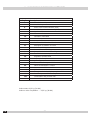
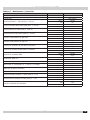
7DEOH&RPEXVWLRQ$LUDQG9HQW3LSH)LWWLQJV
&DWHJRU\,&KLPQH\9HQW
Item Material Standards
Vent Pipe & Fittings
Type B Vent UL 441, ULC S605
Masonry Chimney
- must conform to
proper sizing and
materials
National Fuel Gas
Code, ANSI Z223.1/
NFPA 54
Combustion Air
Stainelss Steel,
PVC, CPVC, PP,
Aluminum
ANSI/ASTM D2564,
ANSI/ASTM F493,
UL 1738/ULC636-08
EN
16
EN

17
6 - COMBUSTION AIR AND VENT PIPING OF DIRECT VENT AND CATEGORY III
Induced Draft Boilers
Horizontal (Category III) venting systems installation
shall conform to the requirements of the authority having
jurisdiction or, in the absence of such requirements, to
the National Fuel Gas Code, ANSI Z223.1/NFPA 54, and/
or Natural Gas and Propane Installation Code, CAN/CSA
B149.1
1.
Boilers may be vented horizontally. Vent pipe is pitched
down from boiler to vent termination. Do not connect
other appliances to this vent.
2.
Vent Pipe Material UL Listed - AL294C Stainless Steel
YHQWSLSHDQG¿WWLQJV
3.
Clearance to Combustible Materials: For stainless steel
vent pipe maintain 6” minimum air space clearance to
combustible materials.
4.
Vent Pipe Size: 3” vent pipe connected directly to the
outlet of the induced draft blower.
5.
Vent Pipe Length:
A. For stainless steel vent pipe, the maximum
horizontal vent length is 65 equivalent feet.
B. Minimum horizontal vent length is 5 equivalent
feet.
C. For 3” 90° elbows = 5 equivalent feet of vent
length.
6.
Vent Termination Fitting: For all vent pipe materials,
you may use either:
A. HOERZSRLQWLQJGRZQ¿WWHGZLWKDPLQLPXP
1/4” mesh screen to keep out rodents and birds.
The elbow shall be of the same material and size
as vent pipe. The elbow exit should be at least 6”
away from exterior wall.
-or-
B. Concentric side wall vent hood.
7.
Vent Pipe Termination Location :
A. When venting through combustible walls,
combustible clearances must be considered. ECR
YHQWWHUPLQDWLRQLVDFHUWL¿HGGLUHFWYHQW
termination (for Catagory III venting) providing
both the outside vent termination and a double
wall pipe for passing through a combustible
wall up to 10” thick. Vent terminations by other
manufacturers may also be used as long as they
DUHFHUWL¿HGIRUFDWDJRU\,,,YHQWLQJ
B. ,IWKHHOERZLVWKHWHUPLQDWLRQ¿WWLQJRIFKRLFH
then the single wall pipe will be passing through the
side wall. For combustible walls, a UL listed thimble
shall be used where the single wall pipe passes
through the wall.
C. For single wall pipe through non-combustible
walls, the hole through the wall need only be large
enough to maintain the pitch of the vent pipe, and
provide proper sealing. A thimble is not required for
single wall pipe passing through non-combustible
walls.
D. The venting system shall terminate at least 3 feet
0.9m) above any forced air inlet located within
10 feet (3m). The venting system shall terminate
at least 4 feet (1.2m) below, 4 feet (1.2m)
horizontally from, or 1 foot (300 mm) above any
door, window, or gravity air inlet into any building.
The bottom of the vent shall be located at least 12
inches (300mm) above grade. Termination of the
vent shall be not less than 7 feet (2.13m) above
adjacent public walkway. The vent terminal shall
not be installed closer than 3 feet (0.9m) from the
inside corner of an L shaped structure. Termination
of the vent should be kept at least 3 feet (0.9m)
away from vegetation. The venting system shall
terminate at least 4 feet horizontally from, and in
no case above or below, unless a 4 foot horizontal
distance is maintained, from electric meters, gas
meters, regulators, and relief equipment.
• The venting system shall terminate at least 4 feet
EHORZDQ\HDYHVRI¿WRUURRIRYHUKDQJ
• The venting system shall not terminate
underneath any deck, patio, or similar structure.
• Put vent on a wall away from the prevailing
winter wind. Locate or guard the vent to prevent
accidental contact with people or pets.
• Terminate the vent above normal snow-line. Avoid
locations where snow may drift and block the
vent. Ice or snow may cause the boiler to shut
down if the vent becomes obstructed.
• 8QGHUFHUWDLQFRQGLWLRQVÀXHJDVZLOOFRQGHQVH
forming moisture. In such cases, steps should be
taken to prevent building materials at the vent
WHUPLQDOIURPEHLQJGDPDJHGE\H[KDXVWRIÀXH
gas.
United States - Terminate vent system at least
4 feet (1.22m) horizontally from, and in no case
above or below, unless a 4 feet (1.22m) horizontal
distance is maintained, from electric meters, gas
meters, regulators and relief equipment.
Canada - Terminate vent system at least 6 feet
(1.83 m) horizontally from, and in no case above
or below, unless a 6 feet (1.83m) horizontal
distance is maintained, from electric meters, gas
meters, regulators and relief equipment.
8.
Joining and Sealing the Vent Pipe: The vent pipe needs
to be both watertight and gas tight. Seal all joints and
seams following vent pipe manufacture’s installation
instructions.
9.
Support Spacing: Do not restrict thermal expansion
movement of the vent. The vent pipe must expand
and contract freely with temperature change. Each run
of vent piping shall be supported following vent pipe
manufacture’s instructions.
EN
17
EN

18
WARNING
Vent extending through exterior wall shall not
terminate adjacent to wall or below building
extensions such as eaves, balconies, parapets or
decks. Failure to comply could result in death or
serious injury.
!
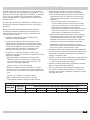
7DEOH&RPEXVWLRQ$LUDQG9HQW3LSH)LWWLQJV
6 - COMBUSTION AIR AND VENT PIPING OF DIRECT VENT AND CATEGORY III
10.
If the horizontal vent must go through a crawl space or
other unheated space, the cool temperatures will likely
FDXVHWKHÀXHJDVHVWRFRQWLQXRXVO\FRQGHQVHLQVLGH
the vent pipe. Do not insulate the vent pipe. It must be
visible for monthly inspection. Insure that the vent pipe
is properly pitched away from the boiler, with no low
spots, so that condensate in the vent will drain away
from the boiler. An insulated enclosure or chase, with
access for inspection and servicing of the vent, may
be required to prevent freezing of liquid condensate.
Consult the vent pipe manufacturer’s instructions for
VSHFL¿FJXLGHOLQHV
11.
At beginning of each heating season and monthly
during the heating season, check all vent pipes and
vent terminal to make sure there are no obstructions.
Periodically clean the screen in the vent terminal.
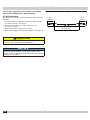
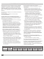
(TXLYDOHQW/HQJWKRI9HQWLQJ&RPSRQHQWV
IWHTXLYDOHQWIRUD´HOERZ
IWHTXLYDOHQWIRUD´HOERZ
EN
7\SH Item Diameter 0LQ/HQJKW 0D[/HQJKW Material Standards
Direct vent
Vent 3” 5 ft 65 ft
AL294C Stainless
Steel, Aluminum
UL1738,
ULC S636
Air intake 3” 5 ft 65 ft
Stainelss Steel,
PVC, CPVC, PP,
Aluminum
ANSI/ASTM
D2564, ANSI/
ASTM F493, UL
1738/ULC636-08
&DWHJRU\,,, Vent 3” 5 ft 65 ft
AL294C Stainless
Steel, Aluminum
UL1738,
ULC S636
18
EN

19
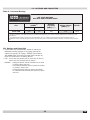
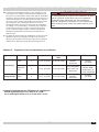
6 - COMBUSTION AIR AND VENTILATION
Provide combustion air and ventilation air in accordance
with the section “Air for Combustion and Ventilation,” of the
National Fuel Gas Code, ANSI Z223.1/NFPA 54, or Sections
8.2, 8.3 or 8.4 of Natural Gas and Propane Installation
Code, CAN/CSA B149.1, or applicable provisions of local
building codes.
Provide make-up air where exhaust fans, clothes dryers,
and kitchen ventilation equipment interfere with proper
operation.
National Fuel Gas Code recognizes several methods
of obtaining adequate ventilation and combustion air.
Requirements of the authority having jurisdiction may
override these methods.
• Engineered Installations. Must be approved by
authority having jurisdictions.
• Mechanical Air Supply. Provide minimum of 0.35
cfm per Mbh for all appliances located within space.
Additional requirements where exhaust fans installed.
Interlock each appliance to mechanical air supply
system to prevent main burner operation when
mechanical air supply system not operating.
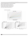
• All Indoor Air. Calculate minimum volume for all
appliances in space. Use a different method if minimum
volume not available.
¸Standard Method. Cannot be used if known air
LQ¿OWUDWLRQUDWHLVOHVVWKDQDLUFKDQJHVSHU
hour. See Table 4 for space with boiler only. Use
equation for multiple appliances.
9ROXPHIW[7RWDO,QSXW>0EK@
¸.QRZQ$LU,Q¿OWUDWLRQ5DWH6HH7DEOHIRUVSDFH
with boiler only. Use equation for multiple appliances.
'RQRWXVHDQDLULQ¿OWUDWLRQUDWH$&+JUHDWHUWKDQ
0.60.
9ROXPHIW$&+[7RWDO,QSXW>0EK@
¸Refer to National Fuel Gas Code for opening
requirements between connection indoor spaces
• All Outdoor Air. Provide permanent opening(s)
communicating directly or by ducts with outdoors.
¸Two Permanent Opening Method. Provide opening
commencing within 12 inches of top and second
opening commencing within 12 inches of bottom
enclosure.
Direct communication with outdoors or
communicating through vertical ducts. Provide
minimum free area of 1 in 2 per 4 Mbh of total
input rating of all appliances in enclosure.
Communicating through horizontal ducts. Provide
minimum free area of 1 in 2 per 2 Mbh of total
input rating of all appliances in enclosure.
¸One Permanent Opening Method. Provide opening
commencing within 12 inches of top of enclosure.
Provide minimum clearance of 1 inch on sides
and back and 6 inches on front of boiler (does not
supersede clearance to combustible materials).
¸Combination Indoor and Outdoor Air. Refer to
National Fuel Gas Code for additional requirements
for louvers, grilles, screens and air ducts.
• Combination Indoor and Outdoor Air. Refer toNational
Fuel Gas Code for application information. National Gas
and Propane Installation Code Requires providing air
supply in accordance with:
• Section 8.2 and 8.3 when combination of applianceshas
a total input of up to and including 400 Mbh (120kW).
Does not have draft control device.
• Section 8.4 when combination of appliances has total
input exceeding 400 Mbh (120 kW).
• Refer to Natural Gas and Propane Installation Code
IRUVSHFL¿FDLUVXSSO\UHTXLUHPHQWVIRUHQFORVXUHRU
structure where boiler is installed, including air supply
openings and ducts.
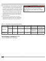
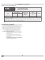
7DEOH6SDFH5HTXLUHGIRU$&+
,QSXW0EK
Standard
0HWKRG
.QRZQ$LU,Q¿OWUDWLRQ5DWH0HWKRG$LU&KDQJHV3HU+RXU
0.1 0.2 0.3 0.4 0.5 0.6
150 7500 22,500 11,250 7,500 5,625 4,500 3,750
EN
19
EN

20
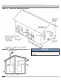
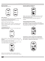
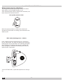
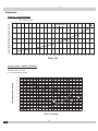
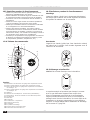
6 - COMBUSTION AIR AND VENT PIPING
( &RPEXVWLRQ$LU = Venting)
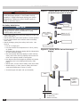
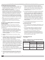
Figure 12 - Horizontal Venting Clearances
Figure 13 7\SLFDO9HQWDQG$LU,QWDNH
Arrangements
NOTICE
Maintain 12” (30cm) US, 18” (46cm) Canada
clearance above highest anticipated snow level
or grade.
EN
20
EN
La page est en cours de chargement...
La page est en cours de chargement...
La page est en cours de chargement...
La page est en cours de chargement...
La page est en cours de chargement...
La page est en cours de chargement...
La page est en cours de chargement...
La page est en cours de chargement...
La page est en cours de chargement...
La page est en cours de chargement...
La page est en cours de chargement...
La page est en cours de chargement...
La page est en cours de chargement...
La page est en cours de chargement...
La page est en cours de chargement...
La page est en cours de chargement...
La page est en cours de chargement...
La page est en cours de chargement...
La page est en cours de chargement...
La page est en cours de chargement...
La page est en cours de chargement...
La page est en cours de chargement...
La page est en cours de chargement...
La page est en cours de chargement...
La page est en cours de chargement...
La page est en cours de chargement...
La page est en cours de chargement...
La page est en cours de chargement...
La page est en cours de chargement...
La page est en cours de chargement...
La page est en cours de chargement...
La page est en cours de chargement...
La page est en cours de chargement...
La page est en cours de chargement...
La page est en cours de chargement...
La page est en cours de chargement...
La page est en cours de chargement...
La page est en cours de chargement...
La page est en cours de chargement...
La page est en cours de chargement...
La page est en cours de chargement...
La page est en cours de chargement...
La page est en cours de chargement...
La page est en cours de chargement...
La page est en cours de chargement...
La page est en cours de chargement...
La page est en cours de chargement...
La page est en cours de chargement...
La page est en cours de chargement...
La page est en cours de chargement...
La page est en cours de chargement...
La page est en cours de chargement...
La page est en cours de chargement...
La page est en cours de chargement...
La page est en cours de chargement...
La page est en cours de chargement...
La page est en cours de chargement...
La page est en cours de chargement...
La page est en cours de chargement...
La page est en cours de chargement...
La page est en cours de chargement...
La page est en cours de chargement...
La page est en cours de chargement...
La page est en cours de chargement...
La page est en cours de chargement...
La page est en cours de chargement...
La page est en cours de chargement...
La page est en cours de chargement...
La page est en cours de chargement...
La page est en cours de chargement...
La page est en cours de chargement...
La page est en cours de chargement...
-
 1
1
-
 2
2
-
 3
3
-
 4
4
-
 5
5
-
 6
6
-
 7
7
-
 8
8
-
 9
9
-
 10
10
-
 11
11
-
 12
12
-
 13
13
-
 14
14
-
 15
15
-
 16
16
-
 17
17
-
 18
18
-
 19
19
-
 20
20
-
 21
21
-
 22
22
-
 23
23
-
 24
24
-
 25
25
-
 26
26
-
 27
27
-
 28
28
-
 29
29
-
 30
30
-
 31
31
-
 32
32
-
 33
33
-
 34
34
-
 35
35
-
 36
36
-
 37
37
-
 38
38
-
 39
39
-
 40
40
-
 41
41
-
 42
42
-
 43
43
-
 44
44
-
 45
45
-
 46
46
-
 47
47
-
 48
48
-
 49
49
-
 50
50
-
 51
51
-
 52
52
-
 53
53
-
 54
54
-
 55
55
-
 56
56
-
 57
57
-
 58
58
-
 59
59
-
 60
60
-
 61
61
-
 62
62
-
 63
63
-
 64
64
-
 65
65
-
 66
66
-
 67
67
-
 68
68
-
 69
69
-
 70
70
-
 71
71
-
 72
72
-
 73
73
-
 74
74
-
 75
75
-
 76
76
-
 77
77
-
 78
78
-
 79
79
-
 80
80
-
 81
81
-
 82
82
-
 83
83
-
 84
84
-
 85
85
-
 86
86
-
 87
87
-
 88
88
-
 89
89
-
 90
90
-
 91
91
-
 92
92


Dunkirk CCB-150 Installation & Operation Manual
- Taper
- Installation & Operation Manual
- Ce manuel convient également à
dans d''autres langues
- English: Dunkirk CCB-150
Documents connexes
-
Dunkirk DWB Series Manuel utilisateur
-
-
Dunkirk DCC/DCB High Efficiency Wall Mounted Modulating Condensing Boiler Installation & Operation Manual
-
-
-
-
-
Autres documents
-
Raypak XVers L 406L-856L Type H Mode d'emploi
-
Bradford White BMGH1600 Manuel utilisateur
-
Weil-McLain CGa Gas Boiler Series 2 Manuel utilisateur
-
 NTI GF 200 Quick Installation Manual
-
 Burham V11H Series Manuel utilisateur
-
-
-
Hobart CL44eNER Instructions Manual
-
Empire DVP36PP32EN-3 Le manuel du propriétaire
-
Ferroli D F24 Manuel utilisateur

