
Verifone Part Number DOC474-003-EN-A, Revision A
V240m
Installation Guide

All rights reserved. No part of the contents of this document may be reproduced or transmitted in any form without the written
permission of Verifone, Inc.
The information contained in this document is subject to change without notice. Although Verifone has attempted to ensure the
accuracy of the contents of this document, this document may include errors or omissions. The examples and sample programs are
for illustration only and may not be suited for your purpose. You should verify the applicability of any example or sample program
before placing the software into productive use. This document, including without limitation the examples and software programs, is
supplied “As-Is.”
Verifone Inc.
1-800-Verifone
www.verifone.com
Verifone Part Number DOC474-003-EN-A, Revision A
V240m Installation Guide
© 2017 Verifone, Inc.
Verifone and the Verifone logo, are registered trademarks of Verifone. Other brand names or trademarks associated with Verifone’s
products and services are trademarks of Verifone, Inc.
All other brand names and trademarks appearing in this manual are the property of their respective holders.
Product Warranty
For product warranty information, go to http://www.verifone.com/terms.
Comments? Please e-mail all comments on this document to your local Verifone Support Team.

V240M INSTALLATION GUIDE 3
CONTENTS
PREFACE . . . . . . . . . . . . . . . . . . . . . . . . . . . . . . . . . . . . . . . 5
Audience. . . . . . . . . . . . . . . . . . . . . . . . . . . . . . . . . . . . . . . . . . . . . . . . . . . . . . . . 5
Organization . . . . . . . . . . . . . . . . . . . . . . . . . . . . . . . . . . . . . . . . . . . . . . . . . . . . . 5
Related Documentation . . . . . . . . . . . . . . . . . . . . . . . . . . . . . . . . . . . . . . . . . . . . 5
Guide Conventions. . . . . . . . . . . . . . . . . . . . . . . . . . . . . . . . . . . . . . . . . . . . . . . . 5
Acronym Definitions . . . . . . . . . . . . . . . . . . . . . . . . . . . . . . . . . . . . . . . . . . . . 6
CHAPTER 1
Overview V240m Terminal . . . . . . . . . . . . . . . . . . . . . . . . . . . . . . . . . . . . . . . . . . . . . . . . . . 7
Front Functions . . . . . . . . . . . . . . . . . . . . . . . . . . . . . . . . . . . . . . . . . . . . . . . . 7
Back Functions . . . . . . . . . . . . . . . . . . . . . . . . . . . . . . . . . . . . . . . . . . . . . . . . 8
V240m Bases . . . . . . . . . . . . . . . . . . . . . . . . . . . . . . . . . . . . . . . . . . . . . . . . . . . . 9
V240m Charging Base . . . . . . . . . . . . . . . . . . . . . . . . . . . . . . . . . . . . . . . . . . 9
V240m Full-Feature Base . . . . . . . . . . . . . . . . . . . . . . . . . . . . . . . . . . . . . . . 10
Features and Benefits . . . . . . . . . . . . . . . . . . . . . . . . . . . . . . . . . . . . . . . . . . . . 11
Exceptional Ease of Use and Ergonomics . . . . . . . . . . . . . . . . . . . . . . . . . . 11
Critical Security Protection . . . . . . . . . . . . . . . . . . . . . . . . . . . . . . . . . . . . . . 11
CHAPTER 2
Setup Selecting Location . . . . . . . . . . . . . . . . . . . . . . . . . . . . . . . . . . . . . . . . . . . . . . . 13
Environmental Factors . . . . . . . . . . . . . . . . . . . . . . . . . . . . . . . . . . . . . . . . . 14
Electrical Considerations . . . . . . . . . . . . . . . . . . . . . . . . . . . . . . . . . . . . . . . 14
Contactless Considerations . . . . . . . . . . . . . . . . . . . . . . . . . . . . . . . . . . . . . 14
PIN Protection Measures . . . . . . . . . . . . . . . . . . . . . . . . . . . . . . . . . . . . . . . . . . 14
Unpacking Shipping Carton . . . . . . . . . . . . . . . . . . . . . . . . . . . . . . . . . . . . . . . . 15
MSAM/uSD Cards . . . . . . . . . . . . . . . . . . . . . . . . . . . . . . . . . . . . . . . . . . . . . . . 15
Opening Card Compartment. . . . . . . . . . . . . . . . . . . . . . . . . . . . . . . . . . . . . 15
Changing or Installing MSAMs . . . . . . . . . . . . . . . . . . . . . . . . . . . . . . . . . . . 16
Changing or Installing Micro SD Card. . . . . . . . . . . . . . . . . . . . . . . . . . . . . . 17
Changing or Installing SIM Card. . . . . . . . . . . . . . . . . . . . . . . . . . . . . . . . . . 18
Loading Printer Paper. . . . . . . . . . . . . . . . . . . . . . . . . . . . . . . . . . . . . . . . . . . . . 18
Power Supply . . . . . . . . . . . . . . . . . . . . . . . . . . . . . . . . . . . . . . . . . . . . . . . . . . . 19
USB Power Supply . . . . . . . . . . . . . . . . . . . . . . . . . . . . . . . . . . . . . . . . . . . . 21
Cable Connections . . . . . . . . . . . . . . . . . . . . . . . . . . . . . . . . . . . . . . . . . . . . . . . 21
Cable Connections Using the Full-Feature Base . . . . . . . . . . . . . . . . . . . . . 22
Smart Card Reader . . . . . . . . . . . . . . . . . . . . . . . . . . . . . . . . . . . . . . . . . . . . . . 23
Magnetic Stripe Card Reader Use . . . . . . . . . . . . . . . . . . . . . . . . . . . . . . . . . . . 24
Contactless Transactions . . . . . . . . . . . . . . . . . . . . . . . . . . . . . . . . . . . . . . . . . . 24
Optional Accessories . . . . . . . . . . . . . . . . . . . . . . . . . . . . . . . . . . . . . . . . . . . . . 25
Full-Feature Base . . . . . . . . . . . . . . . . . . . . . . . . . . . . . . . . . . . . . . . . . . . . . 25
Charging Base . . . . . . . . . . . . . . . . . . . . . . . . . . . . . . . . . . . . . . . . . . . . . . . 25
Periodic Inspection . . . . . . . . . . . . . . . . . . . . . . . . . . . . . . . . . . . . . . . . . . . . . . . 26

4 V240M INSTALLATION GUIDE
CHAPTER 3
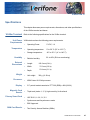
Specifications V240m Terminal . . . . . . . . . . . . . . . . . . . . . . . . . . . . . . . . . . . . . . . . . . . . . . . . . 27
Unit Power Requirements . . . . . . . . . . . . . . . . . . . . . . . . . . . . . . . . . . . . . . . 27
Temperature . . . . . . . . . . . . . . . . . . . . . . . . . . . . . . . . . . . . . . . . . . . . . . . . . 27
Humidity . . . . . . . . . . . . . . . . . . . . . . . . . . . . . . . . . . . . . . . . . . . . . . . . . . . . 27
External Dimensions . . . . . . . . . . . . . . . . . . . . . . . . . . . . . . . . . . . . . . . . . . . 27
Weight. . . . . . . . . . . . . . . . . . . . . . . . . . . . . . . . . . . . . . . . . . . . . . . . . . . . . . 27
Processor . . . . . . . . . . . . . . . . . . . . . . . . . . . . . . . . . . . . . . . . . . . . . . . . . . . 27
Display . . . . . . . . . . . . . . . . . . . . . . . . . . . . . . . . . . . . . . . . . . . . . . . . . . . . . 27
Magnetic Card Reader . . . . . . . . . . . . . . . . . . . . . . . . . . . . . . . . . . . . . . . . . 27
Primary Smart Card . . . . . . . . . . . . . . . . . . . . . . . . . . . . . . . . . . . . . . . . . . . 27
SAM Card Reader. . . . . . . . . . . . . . . . . . . . . . . . . . . . . . . . . . . . . . . . . . . . . 27
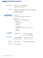
Battery Pack . . . . . . . . . . . . . . . . . . . . . . . . . . . . . . . . . . . . . . . . . . . . . . . . . 28
Security . . . . . . . . . . . . . . . . . . . . . . . . . . . . . . . . . . . . . . . . . . . . . . . . . . . . . 28
V240m Bases . . . . . . . . . . . . . . . . . . . . . . . . . . . . . . . . . . . . . . . . . . . . . . . . . . . 28
Unit Power Requirements . . . . . . . . . . . . . . . . . . . . . . . . . . . . . . . . . . . . . . . 28
Temperature . . . . . . . . . . . . . . . . . . . . . . . . . . . . . . . . . . . . . . . . . . . . . . . . . 28
Humidity . . . . . . . . . . . . . . . . . . . . . . . . . . . . . . . . . . . . . . . . . . . . . . . . . . . . 28
Security . . . . . . . . . . . . . . . . . . . . . . . . . . . . . . . . . . . . . . . . . . . . . . . . . . . . . 28
CHAPTER 4
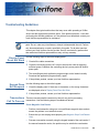
Troubleshooting
Guidelines
Display Panel Does Not Work . . . . . . . . . . . . . . . . . . . . . . . . . . . . . . . . . . . . . . 29
Keypad Does Not Respond . . . . . . . . . . . . . . . . . . . . . . . . . . . . . . . . . . . . . . . . 29
Transactions Fail To Process . . . . . . . . . . . . . . . . . . . . . . . . . . . . . . . . . . . . . . . 29
CHAPTER 5
Service and Support Maintenance and Cleaning. . . . . . . . . . . . . . . . . . . . . . . . . . . . . . . . . . . . . . . . . 31
Service Returns . . . . . . . . . . . . . . . . . . . . . . . . . . . . . . . . . . . . . . . . . . . . . . . . . 31
Accessories and Documentation . . . . . . . . . . . . . . . . . . . . . . . . . . . . . . . . . . . . 33
Cables. . . . . . . . . . . . . . . . . . . . . . . . . . . . . . . . . . . . . . . . . . . . . . . . . . . . . . 33
Power Supply . . . . . . . . . . . . . . . . . . . . . . . . . . . . . . . . . . . . . . . . . . . . . . . . 33
Accessories. . . . . . . . . . . . . . . . . . . . . . . . . . . . . . . . . . . . . . . . . . . . . . . . . . 33
Documentation . . . . . . . . . . . . . . . . . . . . . . . . . . . . . . . . . . . . . . . . . . . . . . . 33
APPENDIX A Caution and Warning Messages . . . . . . . . . . . . . . . . . . . . . . . . . . . . . . . . . . . . 35

V240M INSTALLATION GUIDE 5
PREFACE
This guide is the primary source of information for setting up and installing V240m
device.
Audience
This guide provides simple descriptions of the V240m features and the basic
information for installing and configuring the V240m.
Organization
This guide is organized as follows:
Chapter 1, Overview. Provides an overview of a V240m device.
Chapter 2, Setup. Explains how to set up and install the V240m and establish
connections with other devices.
Chapter 3, Specifications. Discusses the power requirements and dimensions of
V240m.
Chapter 4, Troubleshooting Guidelines. Provides troubleshooting tips.
Chapter 5, Service and Support. Provides information on contacting your Verifone
service provider, ordering accessories or documentation from Verifone, and
maintaining the V240m unit.
Appendix A, Caution and Warning Messages. Shows the UL/cUL certification-
compliant translations of all Warning and Caution messages in this installation
guide.
Related
Documentation
To learn more about the V240m device, please refer to the following documents
and their associated Verifone Part Numbers (VPN):
Guide
Conventions
Please refer to the following document conventions for quickly identifying special
formatting.
Table 1 describes these conventions and provides examples of their use.
V240m Certifications and Regulations
VPN DOC474-001-EN
V240m Quick Installation Guide VPN DOC474-002-EN
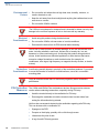
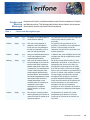
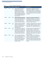
Table 1 Document Conventions
Convention Meaning Example
Blue Text in blue indicates terms that
are cross-references.
See Guide Conventions.
Italics Italic typeface indicates book
titles or emphasis.
You must not use this unit
underwater.

PREFACE
Guide Conventions
6 V240M INSTALLATION GUIDE
Acronym Definitions
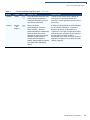
Please refer to Table 2 for the acronyms used in this manual.
The pencil icon is used to
highlight important information.
RS-232-type devices do not work
on the communication port.
The caution symbol indicates
hardware or software failure, or
loss of data.
The unit is not waterproof or
dustproof, and is intended for
indoor use only.
The lightning symbol is used as a
warning when bodily injury might
occur.
Due to risk of shock do not use
the unit near water.
Table 1 Document Conventions
Convention Meaning Example
NOTE
CAUTION
WARNING
Table 2 Acronym Definitions
Acronym Definitions
3DES Triple Data Encryption Algorithm
AC Alternating Current
ANSI American National Standards Institute
cUL Underwriters' Laboratories of Canada
DC Direct Current
DUKPT Derived Unique Key Per Transaction Method as defined in the
VISA’s POS Equipment Requirement: PIN processing and Data
Authentication, International Version 1.0, August 1988
ECR Electronic Cash Register
EMV Europay, MasterCard, and Visa
ISO International Organization for Standardization
MRA Merchandise Return Authorization
MSAM Multiple Secure Access Module
LAN Local Area Network
LCD Liquid Crystal Display
LED Light-Emitting Diode
PED PIN Entry Device
PIN Personal Identification Number
POS Point-of-Sale
RS-232 Recommend Standard number 232
SAM Secure Access Module
UL Underwriters Laboratories
USB Universal Serial Bus
VPN Verifone Part Number

V240M INSTALLATION GUIDE 7
CHAPTER 1
Overview
This chapter presents the basics on the V240m terminal and base.
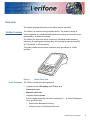
V240m Terminal
The V240m is a consumer-facing handheld device. The product’s design is
equally appealing as a handheld PINpad and robust enough to look and function
appropriately in a fixed mount setting.
The V240m can utilize over-the-air connectivity, facilitating mobile telephony
technology for sending and receiving data, using existing operator-provided 2G,
Wi-Fi, Bluetooth, or 3G connectivity.
This guide provides an introduction and basic setup procedures for V240m
terminals.
Figure 1 V240m Front View
Front Functions
The V240m includes the following features:
• Capacitive touch LCD display and CTLS tap area
• Smart card reader
• Magnetic card reader
• Integrated thermal printer
• Secure keypad supporting 3x5 matrix containing 0-9, *, #, Cancel, Backspace/
Clear, and Enter keys.
• Dual-function Backspace/Clear key.
• Customer-entry for Cancel and Enter keys.

OVERVIEW
V240m Terminal
8 V240M INSTALLATION GUIDE
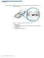
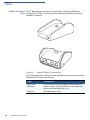
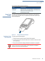
Back Functions
After removing the rear cover and battery, the underside of the V240m device
shows the following:
Figure 2 V240m Underside Compartment View
• A Micro SD slot
• Dual MSAM slots to support stored-value card programs or other merchant
card requirements
• Dual SIM Card compartments
SIM 1
SAM 1
SAM 2
SIM 2
SD

OVERVIEW
V240m Bases
V240
M INSTALLATION GUIDE 9
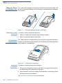
V240m Bases
The V240m Base provides a stable mounted platform for the V240m terminal. The
Base comes in two versions:
• V240m Charging Base
• V240m Full-Feature Base
The Charging Base supports charging only with no communication functionality.
The Full-Feature Base supports several connectivity options and provides serial
connection for peripherals (like ECR, check reader, barcode reader, etc.). The
USB host port is for maintenance purposes and supports a USB flash drive.
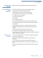
V240m Charging
Base
The Charging Base accommodates and supplies power to the V240m and
V240m Plus portable terminals.
Figure 3 V240m Charging Base, Front and Rear

OVERVIEW
V240m Bases
10 V240M INSTALLATION GUIDE
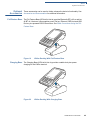
V240m Full-Feature
Base
The FF Base supports any failover communication via dial up and Ethernet
connections for V240m. The failover will be supported in all network interfaces
available in a terminal.
Figure 4 V240m FF Base, Front and Rear
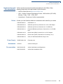
The FF Base supports a minimum of seven simultaneous terminal connections via
Bluetooth (BT) as well as the following:
Cable Configuration
Ethernet port RJ-45 socket (for connecting PINPad to LAN infrastructure)
RS232 port RS232 socket (for connecting PINPad to LAN infrastructure),
MOD-8 socket, Mini USB & DC-in jack
USB ports Mini USB and type A USB

OVERVIEW
Features and Benefits
V240
M INSTALLATION GUIDE 11
Features and
Benefits
The V240m terminal and V240m Bases provide the following functionality:
Exceptional Ease of
Use and
Ergonomics
• Touch screen enables easy menu control and signature capture.
• Battery-powered for mobility and portable operation.
• Integrated thermal printer for fast transaction processing.
• Large, hard-rubber keys provide improved tactile feedback.
• 3.5” capacitive touch screen display.
• 2G capability (for V240m only).
• 3G functionality
• WiFi- and Bluetooth-capable.
• Intuitive keypad interface simplify training and reduce support requests.
• Using the Full-Feature Base, connects with most POS payment terminals,
PCs, and ECRs.
• Supports payment transactions in a variety of payment environments.
• Rugged and reliable design absorbs hard knocks found at point-of-sale
counters.
• Sleek and stylish shape occupies minimal counter space.
• Bold, ergonomic design fits comfortably in the palm of a hand.
• Optional Charging or Full-Feature Bases expand functionality while providing
a stable, battery-charging platform.
Critical Security
Protection
• Offers a choice of Master/Session or DUKPT key-management methods to
protect PIN-based transactions.
• Offers secure, reliable PIN input for expanding range of PIN-based
transactions.
• PCI 5.x-compliant for secure solutions, meeting the PED standard.
• Meets ISO and ANSI standards for PIN encryption, key management, and
MAC.
• Key injection simplified and secured with Verifone’s SecureKit key loading
software.

OVERVIEW
Features and Benefits
12 V240M INSTALLATION GUIDE

V240M INSTALLATION GUIDE 13
CHAPTER 2
Setup
This chapter describes the setup procedure for the V240m and charging base, in
the following sections:
• Selecting Location
• PIN Protection Measures
• Unpacking Shipping Carton
• MSAM/uSD Cards
• Power Supply
• Cable Connections
• Smart Card Reader
• Magnetic Stripe Card Reader Use
• Contactless Transactions
• Optional Accessories
Selecting
Location
Use the following guidelines to select the best location for the V240m device.
To Select a Location
Choose a location convenient for both merchant and client:
• Far from heavy metal objects,
• A flat support surface such as a countertop or a table,
• Near a power outlet and the terminal or computer that connects to the V240m.
WARNING
For safety, do not string cables or cords across a walkway.

SETUP
PIN Protection Measures
14 V240M INSTALLATION GUIDE
Environmental
Factors
• Do not use the unit where there is high heat, dust, humidity, moisture, or
caustic chemicals or oils.
• Keep the unit away from direct sunlight and anything that radiates heat, such
as a stove or a motor.
• Do not use the V240m outdoors.
Electrical
Considerations
• Avoid using this product during electrical storms.
• Do not use the V240m unit near water or in moist conditions.
• Disconnect the device from its POS terminal before cleaning.
Contactless
Considerations
Avoid having metallic objects in proximity of the contactless antenna. If you need
to mount the terminal to vertical or inclined surfaces, use a flat, non-metallic
mounting plate.
PIN Protection
Measures
The V240m and V240m Plus are handover devices. Always exercise extreme
caution when conducting transactions, especially during PIN entry:
• Hand the terminal directly to the cardholder for PIN entry.
• Encourage the cardholder to hold the terminal close to avoid others from
seeing the information being entered.
Verifone also recommends instructing the cardholder regarding safe PIN-entry.
This can be done with a combination of:
• Signage on the PED
• Prompts on the display, possibly with a click-through screen
• Literature at the point of sale
• A logo for safe PIN-entry process.
CAUTION
The V240m is not waterproof or dustproof and is intended for indoor use only. Any
damage to the unit from exposure to rain or dust can void any warranty.
WARNING
Due to risk of electrical shock or terminal damage, do not use the terminal near
water, including a bathtub, wash bowl, kitchen sink or laundry tub, in a wet
basement, or near a swimming pool. Avoid using this product during electrical
storms. Avoid locations near electrical appliances or other devices that cause
excessive voltage fluctuations or emit electrical noise (for example, air
conditioners, neon signs, high frequency or magnetic security devices, or electric
motors).
CAUTION
Using an enclosed metal frame or mount may negatively affect contactless
performance.

SETUP
Unpacking Shipping Carton
V240
M INSTALLATION GUIDE 15
Unpacking
Shipping Carton
Carefully inspect the shipping carton and its contents for possible tampering or
damage.
1 Remove the V240m unit from the shipping carton. The standard package
contains the PIN pad, power pack, battery, and printer paper roll. Refer to
Accessories and Documentation for more information about V240m related
accessories.
Figure 5 V240m Box Contents
2 Remove any protective plastic wrap and place the unit on a table or
countertop.
3 Remove the clear protective film from the display.
4 Replace all the packing materials, close the lid, and save the carton for
repacking or moving the V240m unit or base in the future.
MSAM/uSD
Cards
You may need to install or replace the multiple security access module (MSAM),
Micro Secure Digital (SD) and Subscriber Identity Module (SIM) cards.
Opening Card
Compartment
Use the following steps to get access to the MSAM, SD and SIM card
compartment:
CAUTION
This device is a secure product and any tampering can cause it to cease to
function or operate in an unsecured manner.
WARNING
Do not use a unit that has been tampered with or otherwise damaged. This unit
comes equipped with tamper-evident label. If a label or component appears
damaged, immediately notify the shipping company and your Verifone
representative or service provider.
CAUTION
Observe standard precautions in handling electrostatically sensitive devices.
Electrostatic discharges can damage the equipment. Verifone recommends using
a grounded anti-static wrist strap.

SETUP
MSAM/uSD Cards
16 V240M INSTALLATION GUIDE
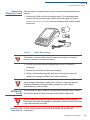
1 Place the terminal face down on a soft and clean surface to protect the display
from scratches.
2 Push down the locking tab and swing out the compartment cover.
Figure 6 Opening Rear Compartment
3 If it is installed, disconnect the battery and place in a secure location.
4 The MSAM, SD and SIM cardholders are now accessible.
Figure 7 V240m Card Holders
Changing or
Installing MSAMs
To change or install MSAM cards:
1 Use steps 1 to 3 of Opening Card Compartment to get to the MSAM
cardholder.
SIM 1
SAM 1
SAM 2
SIM 2
SD

SETUP
MSAM/uSD Cards
V240
M INSTALLATION GUIDE 17
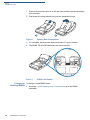
2 Remove the old card, if any, and install the MSAM card by carefully sliding it
into the slot (with the gold contacts facing downward) until fully inserted.
Figure 8 Inserting MSAM Card
3 If you are finished replacing or inserting cards, reconnect the battery and
replace the rear cover.
Changing or
Installing Micro SD
Card
To change or install Micro SD cards:
1 Use steps 1 to 3 of Opening Card Compartment to get to the Micro SD
cardholder.
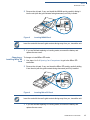
2 Remove the old card, if any, and insert the Micro SD card by carefully sliding
it into the slot (with the gold contacts facing downward) until fully inserted.
Figure 9 Inserting Micro SD Card
3 If you are finished replacing or inserting cards, reconnect the battery and
replace the rear cover.
SIM 1
SAM 1
SD
3!-
NOTE
Insert the card with the card’s gold contacts facing away from you, toward the unit.
SIM 1
SAM 1
SD
3$
NOTE
Insert the card with the card’s gold contacts facing away from you, toward the unit.

SETUP
Loading Printer Paper
18 V240M INSTALLATION GUIDE
Changing or
Installing SIM Card
To change or install SIM cards:
1 Use steps 1 to 3 of Opening Card Compartment to get to the SIM cardholder.
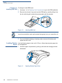
2 Remove the old card, if any, and insert the SIM card by carefully sliding it into
the slot (with the gold contacts facing downward) until fully inserted.
Figure 10 Inserting SIM Card
3 If you are finished replacing or inserting cards, reconnect the battery and
replace the rear cover.
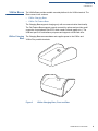
Loading Printer
Paper
Use the following steps to load a roll of 57mm x 40mm thermal printer paper into
the compartment.
1 Unlock the paper compartment by pulling up the latch and swinging the door
downwards.
Figure 11 Opening Printer Paper Door
SIM 1
SAM 1
SD
3)-
NOTE
Insert the card with the card’s gold contacts facing away from you, toward the unit.
1
2

SETUP
Power Supply
V240
M INSTALLATION GUIDE 19
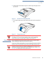
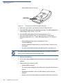
2 Load the paper roll as shown in Figure 12, with the edge of the paper on the
top of the roll.
Figure 12 Procedure for Loading Paper Roll
3 Pull a length of paper up over the serrated cutter and close the compartment
door.
Figure 13 Closing Printer Door
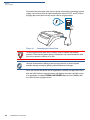
Power Supply
Not all configurations and device contexts require the use of a power supply –
Verifone ships power supply with the terminal as required.
Contact your Verifone representative If you have changed the context in which the
terminal is used or have questions about which power supply should be used.
CAUTION
Before processing transactions in battery mode, make sure you have more than
10% battery life. Do not risk losing transaction data or printing capabilities,
connect the terminal to the power pack if battery level is below 10%.
CAUTION
Using an incorrectly rated power supply can damage the unit or cause it not to
work properly. Use only a power pack with VPN PWR
474-002-01-A (see Service
and Support for detailed power supply specifications).

SETUP
Power Supply
20 V240M INSTALLATION GUIDE
Disconnect the power pack cord from the power outlet before connecting a power
supply. Connect and route all cables between the terminal, ECR, and PC before
plugging the power pack cord into a wall outlet or surge protector.
Figure 14 Connecting the Power Pack
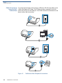
When the terminal has power and an application is loaded, the application starts
after the initial Verifone copyright screen and displays a unique copyright screen.
If no application is loaded, DOWNLOAD NEEDED appears on the display after
the initial Verifone copyright screen.
WARNING
Do not plug the power pack into an outdoor outlet or operate the terminal
outdoors. Disconnecting power during a transaction can cause transaction data
files not yet stored in memory to be lost.
NOTE
Verifone recommends installing a power surge protector to protect against
possible damage caused by lightning strikes and electrical surges.
La page est en cours de chargement...
La page est en cours de chargement...
La page est en cours de chargement...
La page est en cours de chargement...
La page est en cours de chargement...
La page est en cours de chargement...
La page est en cours de chargement...
La page est en cours de chargement...
La page est en cours de chargement...
La page est en cours de chargement...
La page est en cours de chargement...
La page est en cours de chargement...
La page est en cours de chargement...
La page est en cours de chargement...
La page est en cours de chargement...
La page est en cours de chargement...
La page est en cours de chargement...
La page est en cours de chargement...
-
 1
1
-
 2
2
-
 3
3
-
 4
4
-
 5
5
-
 6
6
-
 7
7
-
 8
8
-
 9
9
-
 10
10
-
 11
11
-
 12
12
-
 13
13
-
 14
14
-
 15
15
-
 16
16
-
 17
17
-
 18
18
-
 19
19
-
 20
20
-
 21
21
-
 22
22
-
 23
23
-
 24
24
-
 25
25
-
 26
26
-
 27
27
-
 28
28
-
 29
29
-
 30
30
-
 31
31
-
 32
32
-
 33
33
-
 34
34
-
 35
35
-
 36
36
-
 37
37
-
 38
38


dans d''autres langues
- English: VeriFone V240m Installation guide
Documents connexes
Autres documents
-
Pax Technology E700 Manuel utilisateur
-
Ingenico iUR 250 Integration Manual
-
-
-
Ingenico MOVE 5000 Manuel utilisateur
-
-
NCR Quantum QR1000 Manuel utilisateur
-
Magtek DynaFlex Kiosk Family Quick Installation Guide
-
-