Yamaha HTR-6280 Le manuel du propriétaire
- Catégorie
- Récepteurs AV
- Taper
- Le manuel du propriétaire

© 2009 Yamaha Corporation All rights reserved.
Printed in Malaysia WR37660
HTR-6280
AV R e c e i ve r
OWNER’S MANUAL
U
00_HTR-6280_U_cv.fm Page 1 Tuesday, March 31, 2009 10:52 AM
Black process 45.0° 240.0 LPI


Caution-i En
• Explanation of Graphical Symbols
The lightning flash with arrowhead symbol, within an
equilateral triangle, is intended to alert you to the
presence of uninsulated “dangerous voltage” within
the product’s enclosure that may be of sufficient
magnitude to constitute a risk of electric shock to
persons.
The exclamation point within an equilateral triangle is
intended to alert you to the presence of important
operating and maintenance (servicing) instructions in
the literature accompanying the appliance.
1 Read these instructions.
2 Keep these instructions.
3 Heed all warnings.
4 Follow all instructions.
5 Do not use this apparatus near water.
6 Clean only with dry cloth.
7 Do not block any ventilation openings. Install in accordance
with the manufacturer’s instructions.
8 Do not install near any heat sources such as radiators, heat
registers, stoves, or other apparatus (including amplifiers)
that produce heat.
9 Do not defeat the safety purpose of the polarized or
grounding-type plug. A polarized plug has two blades with
one wider than the other. A grounding type plug has two
blades and a third grounding prong. The wide blade or the
third prong are provided for your safety. If the provided plug
does not fit into your outlet, consult an electrician for
replacement of the obsolete outlet.
10 Protect the power cord from being walked on or pinched
particularly at plugs, convenience receptacles, and the point
where they exit from the apparatus.
11 Only use attachments/accessories specified by the
manufacturer.
12 Use only with the cart, stand, tripod, bracket,
or table specified by the manufacturer, or sold
with the apparatus. When a cart is used, use
caution when moving the cart/apparatus
combination to avoid injury from tip-over.
13 Unplug this apparatus during lightning storms or when
unused for long periods of time.
14 Refer all servicing to qualified service personnel. Servicing
is required when the apparatus has been damaged in any
way, such as power-supply cord or plug is damaged, liquid
has been spilled or objects have fallen into the apparatus, the
apparatus has been exposed to rain or moisture, does not
operate normally, or has been dropped.
IMPORTANT SAFETY INSTRUCTIONS
Note to CATV system installer:
This reminder is provided to call the CATV system
installer’s attention to Article 820-40 of the NEC that
provides guidelines for proper grounding and, in
particular, specifies that the cable ground shall be
connected to the grounding system of the building, as
close to the point of cable entry as practical.
FCC INFORMATION (for US customers)
1 IMPORTANT NOTICE: DO NOT MODIFY THIS UNIT!
This product, when installed as indicated in the instructions
contained in this manual, meets FCC requirements. Modifications
not expressly approved by Yamaha may void your authority,
granted by the FCC, to use the product.
2 IMPORTANT:
When connecting this product to accessories
and/or another product use only high quality shielded cables.
Cable/s supplied with this product MUST be used. Follow all
installation instructions. Failure to follow instructions could void
your FCC authorization to use this product in the USA.
3NOTE:
This product has been tested and found to comply with
the requirements listed in FCC Regulations, Part 15 for Class “B”
digital devices. Compliance with these requirements provides a
reasonable level of assurance that your use of this product in a
residential environment will not result in harmful interference with
other electronic devices.
This equipment generates/uses radio frequencies and, if not
installed and used according to the instructions found in the users
manual, may cause interference harmful to the operation of other
electronic devices.
Compliance with FCC regulations does not guarantee that
interference will not occur in all installations. If this product is
found to be the source of interference, which can be determined by
turning the unit “OFF” and “ON”, please try to eliminate the
problem by using one of the following measures:
Relocate either this product or the device that is being affected by
the interference.
Utilize power outlets that are on different branch (circuit breaker or
fuse) circuits or install AC line filter/s.
In the case of radio or TV interference, relocate/reorient the
antenna. If the antenna lead-in is 300 ohm ribbon lead, change the
lead-in to coaxial type cable.
If these corrective measures do not produce satisfactory results,
please contact the local retailer authorized to distribute this type of
product. If you can not locate the appropriate retailer, please
contact Yamaha Electronics Corp., U.S.A. 6660 Orangethorpe
Ave, Buena Park, CA 90620.
The above statements apply ONLY to those products distributed by
Yamaha Corporation of America or its subsidiaries.
CAUTION
CAUTION: TO REDUCE THE RISK OF
ELECTRIC SHOCK, DO NOT REMOVE
COVER (OR BACK). NO USER-SERVICEABLE
PARTS INSIDE. REFER SERVICING TO
QUALIFIED SERVICE PERSONNEL.
RISK OF ELECTRIC SHOCK
DO NOT OPEN

Caution-ii En
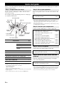
1 To assure the finest performance, please read this manual
carefully. Keep it in a safe place for future reference.
2 Install this sound system in a well ventilated, cool, dry, clean
place – away from direct sunlight, heat sources, vibration,
dust, moisture, and/or cold. Allow ventilation space of at least
30 cm on the top, 20 cm on the left and right, and 20 cm on
the back of this unit.
3 Locate this unit away from other electrical appliances, motors,
or transformers to avoid humming sounds.
4 Do not expose this unit to sudden temperature changes from
cold to hot, and do not locate this unit in an environment with
high humidity (i.e. a room with a humidifier) to prevent
condensation inside this unit, which may cause an electrical
shock, fire, damage to this unit, and/or personal injury.
5 Avoid installing this unit where foreign objects may fall onto
this unit and/or this unit may be exposed to liquid dripping or
splashing. On the top of this unit, do not place:
– Other components, as they may cause damage and/or
discoloration on the surface of this unit.
– Burning objects (i.e. candles), as they may cause fire,
damage to this unit, and/or personal injury.
– Containers with liquid in them, as they may fall and liquid
may cause electrical shock to the user and/or damage to
this unit.
6 Do not cover this unit with a newspaper, tablecloth, curtain,
etc. in order not to obstruct heat radiation. If the temperature
inside this unit rises, it may cause fire, damage to this unit,
and/or personal injury.
7 Do not plug in this unit to a wall outlet until all connections
are complete.
8 Do not operate this unit upside-down. It may overheat,
possibly causing damage.
9 Do not use force on switches, knobs and/or cords.
10 When disconnecting the power cable from the wall outlet,
grasp the plug; do not pull the cable.
11 Do not clean this unit with chemical solvents; this might
damage the finish. Use a clean, dry cloth.
12 Only voltage specified on this unit must be used. Using this
unit with a higher voltage than specified is dangerous and may
cause fire, damage to this unit, and/or personal injury. Yamaha
will not be held responsible for any damage resulting from use
of this unit with a voltage other than specified.
13 To prevent damage by lightning, keep the power cord and
outdoor antennas disconnected from a wall outlet or the unit
during a lightning storm.
14 Do not attempt to modify or fix this unit. Contact qualified
Yamaha service personnel when any service is needed. The
cabinet should never be opened for any reasons.
15 When not planning to use this unit for long periods of time
(i.e. vacation), disconnect the AC power plug from the wall
outlet.
16 Install this unit near the AC outlet and where the AC power
plug can be reached easily.
17 Be sure to read the “Troubleshooting” section on common
operating errors before concluding that this unit is faulty.
18 Before moving this unit, press KMAIN ZONE ON/OFF to
set this unit to the standby mode, and disconnect the AC
power plug from the wall outlet in the main room.
19
The batteries shall not be exposed to excessive heat such as
sunshine, fire or like.
20 Excessive sound pressure from earphones and headphones can
cause hearing loss.
21 When replacing the batteries, be sure to use batteries of the
same type. Danger of explosion may happen if batteries are
incorrectly replaced.
Caution: Read this before operating your unit.
WARNING
TO REDUCE THE RISK OF FIRE OR ELECTRIC
SHOCK, DO NOT EXPOSE THIS UNIT TO RAIN
OR MOISTURE.
As long as this unit is connected to the AC wall outlet,
it is not disconnected from the AC power source even
if you turn off this unit by KMAIN ZONE ON/OFF.
In this state, this unit is designed to consume a very
small quantity of power.
FOR CANADIAN CUSTOMERS
To prevent electric shock, match wide blade of plug to
wide slot and fully insert.
This Class B digital apparatus complies with Canadian
ICES-003.
POUR LES CONSOMMATEURS CANADIENS
Pour éviter les chocs électriques, introduire la lame la
plus large de la fiche dans la borne correspondante de
la prise et pousser jusqu’au fond.
Cet appareil numérique de la classe B est conforme à
la norme NMB-003 du Canada.
IMPORTANT
Please record the serial number of this unit in the space
below.
MODEL:
Serial No.:
The serial number is located on the rear of the unit.
Retain this Owner’s Manual in a safe place for future
reference.

1 En
English
INTRODUCTION
ADDITIONAL
INFORMATION APPENDIX
PREPARATION
BASIC
OPERATION
ADVANCED
OPERATION
Features.................................................................... 2
About this manual................................................... 3
Supplied accessories................................................ 3
Part names and functions....................................... 4
Front panel ................................................................. 4
Rear panel .................................................................. 5
Front panel display..................................................... 6
Remote control........................................................... 7
Quick start guide..................................................... 8
L
Preparing remote control ....................................... 9
Installing batteries in the remote control ................... 9
Using the remote control............................................ 9
Connections ........................................................... 10
Placing speakers....................................................... 10
Connecting speakers ................................................ 11
Information on jacks and cable plugs ...................... 13
Connecting a TV monitor or projector .................... 14
Connecting other components ................................. 15
Connecting a Yamaha iPod universal dock or
Bluetooth™ wireless audio receiver.................... 17
Connecting a USB storage device ........................... 18
Using the VIDEO AUX jacks.................................. 18
Connecting the FM and AM antennas ..................... 18
Connecting the power cable..................................... 19
Turning this unit on and off ..................................... 19
Optimizing the speaker setting for your
listening room (YPAO) ..................................... 20
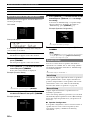
Using Auto Setup..................................................... 20
When an error message is displayed during
measurement ........................................................ 22
When a warning message is displayed after
measurement ........................................................ 22
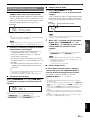
Playback................................................................. 23
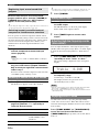
Basic procedure........................................................ 23
Using the SCENE function ...................................... 23
Selecting a source on the GUI screen ...................... 24
Muting audio output................................................. 24
Adjusting high/low frequency sounds
(tone control) ....................................................... 24
Enjoying pure hi-fi sound ........................................ 24
Using your headphones............................................ 25
Displaying input signal information ........................ 25
Changing information on the front panel display .... 25
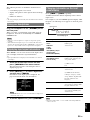
Enjoying the sound field programs ..................... 26
Selecting sound field programs................................ 26
Enjoying unprocessed input sources
(Straight decode mode)........................................ 29
Enjoying sound field programs without surround
speakers (Virtual CINEMA DSP) ....................... 29
Enjoy sound field programs with headphones
(SILENT CINEMA™) ........................................ 29
Using CINEMA DSP 3D mode ............................... 29
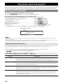
FM/AM tuning ...................................................... 30
Tuning in to the desired FM/AM station
(Frequency tuning) .............................................. 30
Registering FM/AM stations and tuning in (Preset
tuning).................................................................. 30
Using HD Radio™ features
(U.S.A. model only) ........................................... 32
Selecting HD Radio™ audio programs ................... 32
Using the iTunes Tagging feature............................ 32
Displaying HD Radio™ information....................... 33
XM
®
Satellite Radio tuning
(U.S.A. model only) ........................................... 34
Connecting XM Mini-Tuner Home Dock ............... 34
Activating XM Satellite Radio ................................ 34
XM Satellite Radio
®
operations ............................. 35
Registering XM Satellite Radio channels ................ 36
Displaying the XM Satellite Radio™
information .......................................................... 37
SIRIUS Satellite Radio™ tuning
(U.S.A. model only)........................................... 38
Connecting the SiriusConnect™ tuner .................... 38
Activating SIRIUS Satellite Radio™
subscription.......................................................... 38
SIRIUS Satellite Radio™ operations...................... 38
Registering SIRIUS Satellite Radio™ channels...... 40
Setting the Parental Lock......................................... 41
Displaying the SIRIUS Satellite Radio™
information .......................................................... 42
Using iPod™.......................................................... 43
Controlling iPod™................................................... 43
Using Bluetooth™ components ........................... 45
Pairing the Bluetooth™ wireless audio receiver
and your Bluetooth component............................ 45
Playback of the Bluetooth™ component ................. 45
Using USB storage devices................................... 46
Playback of the USB storage device........................ 46
Other functions ..................................................... 47
Using the sleep timer ............................................... 47
Using the HDMI™ control function........................ 47
Setting the option menu for each input source
(Option menu)................................................... 48
Option menu items................................................... 48
Selecting a video signal to be output during an
audio reproduction............................................... 50
Editing surround decoders/sound field
programs ........................................................... 51
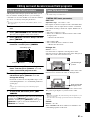
Setting sound field parameters................................. 51
Sound field parameters ............................................ 51
Operating various settings for this unit
(Setup menu) ..................................................... 55
Basic operation of the Setup menu .......................... 56
Speaker Setup .......................................................... 56
Sound Setup ............................................................. 58
Function Setup ......................................................... 59
DSP Parameter ......................................................... 61
Memory Guard......................................................... 61
Using multi-zone configuration ........................... 62
Connecting Zone2.................................................... 62
Controlling Zone2.................................................... 63
Controlling other components with the remote
control................................................................ 64
Setting remote control codes.................................... 64
Resetting all remote control codes........................... 64
Advanced setup..................................................... 65
Troubleshooting .................................................... 67
Glossary ................................................................. 78
Sound field program information ....................... 81
Information on HDMI™...................................... 82
Specifications......................................................... 83
Index ...................................................................... 84
(at the end of this manual)
Contents
INTRODUCTION
PREPARATION
BASIC OPERATION
ADVANCED OPERATION
APPENDIX
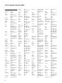
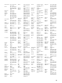
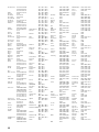
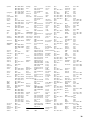
List of remote control codes.................................... i
Information about software................................... x

2 En
INTRODUCTION
■ Built-in 7-channel power amplifier
• Minimum RMS Output Power (1 kHz, 0.7% THD, 8 Ω)
• FRONT L/R: 120 W + 120 W
• CENTER: 120 W
• SURROUND L/R: 120 W + 120 W
• SURROUND BACK L/R: 120 W + 120 W
■ Speaker/Preout outputs
• Speaker terminals (7-channel), extra speaker terminals
(2-channel for presence or Zone2), preout jacks (7.1-
channel)
■ Input/Output terminals
Input terminals
• HDMI input x 4
• Audio/Visual input
[Audio] Digital input (coaxial) x 2, digital input
(optical) x 2, analog input x 2
[Video] Component video x 2, Video x 4
• Audio input (analog) x 2
• Phono input (analog) x 1
• Multi-channel audio input (7.1-channel)
• V-AUX input
[Audio] Analog x 1
[Video] Video x 1
• DOCK terminal to connect a Yamaha iPod universal
dock (such as YDS-11, sold separately) or Bluetooth
wireless audio receiver (such as YBA-10, sold
separately)
• USB port to connect a USB storage device
Output terminals
• Monitor output
[Audio/Video] HDMI x 1
[Video] Component video x 1, Video x 1
• Audio/Visual output
[Audio] Analog x 1
[Video] Video x 1
• Audio output
Analog x 1
• Zone2 output
Analog x 1
Other terminals
Remote input x 1, Remote output x 1
Trigger output x 1
■ Proprietary Yamaha technology for the
creation of sound fields
• CINEMA DSP 3D
• Compressed Music Enhancer mode
• Virtual CINEMA DSP
• SILENT CINEMA
■ Digital audio decoders
• Dolby TrueHD, Dolby Digital Plus decoder
• DTS-HD Master Audio, DTS-HD High Resolution
Audio, DTS Express
• Dolby Digital/Dolby Digital EX decoder
• DTS, DTS 96/24 decoder, DTS-ES Matrix 6.1, DTS-ES
Discrete 6.1
• Dolby Pro Logic/Dolby Pro Logic II/Dolby Pro Logic
IIx decoder
• DSD decoder
• DTS NEO:6 decoder
• Neural Surround decoder (U.S.A. model only)
■ Radio tuners
• FM/AM tuning capability
• HD Radio digital broadcast reception capability (U.S.A.
model only)
•
XM Satellite Radio tuning capability, using XM Mini-
Tuner and Home Dock, sold separately (U.S.A. model only)
•
SIRIUS Satellite Radio tuning capability, using
SiriusConnect tuner, sold separately (U.S.A. model only)
■
HDMI™ (High-Definition Multimedia Interface)
• HDMI interface for standard, enhanced or high-
definition video as well as multi-channel digital audio.
– Automatic audio and video synchronization (lip sync)
information capability
– Deep Color video signal (30/36 bit) transmission
capability
– “x.v.Color” video signal transmission capability
– High refresh rate and high resolution video signals
capability
– High definition digital audio format signals capability
• Analog to analog and HDMI digital video up-
conversion (video ↔ component video → HDMI)
capability for monitor out
•
Analog video input up-scaling for HDMI digital video
output 480i(576i) or 480p(576p)
→
720p, 1080i or 1080p
• HDMI control function supported
■ Automatic speaker setup features
• “YPAO” (Yamaha Parametric Room Acoustic
Optimizer) for automatically optimizing speaker
outputs suitable for listening environments.
■ Other features
• 192-kHz/24-bit D/A converter
• GUI (graphic user interface) menus to optimize this unit
to suit individual audiovisual system
• iPod and USB file browsing and album art display
capability
• Pure Direct mode for pure hi-fi sound for all sources
• Adaptive dynamic range controlling capability
• SCENE function for changing input sources and sound
field programs with one key
• Bi-amplification connection capability
• Sleep timer
• Multi-zone function
• iTunes Tagging function (U.S.A. model only)
Features

3 En
English
INTRODUCTION
ADDITIONAL
INFORMATION APPENDIX
PREPARATION
BASIC
OPERATION
ADVANCED
OPERATION
Manufactured under license from Dolby Laboratories.
Dolby, Pro Logic and the double-D symbol are trademarks of Dolby
Laboratories
Manufactured under license under U.S. Patent No’s:
5,451,942;5,956,674;5,974,380;5,978,762;6,226,616;6,487,535 &
other U.S. and worldwide patents issued & pending. DTS is a
registered trademark and the DTS logos, Symbol, DTS-HD and DTS-
HD Master Audio are trademark of DTS, Inc. © 1996-2007 DTS, Inc.
All Rights Reserved.
Neural Surround
™
name and related logos are trademarks owned
by Neural Audio Corporation.
iPod™
“iPod” is a trademark of Apple Inc., registered in the U.S. and other
countries.
Bluetooth
™
Bluetooth is a registered trademark of Bluetooth SIG and is used by
Yamaha in accordance with a license agreement.
“HDMI”, the “HDMI” logo and “High-Definition Multimedia
Interface” are trademarks, or registered trademarks of HDMI
Licensing LLC.
x.v.Color
“x.v.Color” is a trademark of Sony Corporation.
“SILENT CINEMA” is a trademark of Yamaha Corporation.
SIRIUS, XM and all related marks and logos are trademarks of Sirius
XM Radio Inc. and its subsidiaries. All rights reserved. Service not
available in Alaska and Hawaii.
HD Radio™ Technology Manufactured Under License From iBiquity
Digital Corp. U.S. and Foreign Patents. HD Radio™ and the HD
Radio logo are proprietary trademarks of iBiquity Digital Corp.
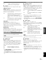
Check that you received all of the following parts.
• Remote control (page 7)
• Batteries (2) (AAA, R03, UM-4) (page 9)
• Optimizer microphone (page 20)
• AM loop antenna (page 18)
• Indoor FM antenna (page 18)
About this manual
• Some operations can be performed by using either the keys on the front panel or the ones on the remote control. In case the key names differ between
the front panel and the remote control, the key name on the remote control is given in parentheses.
• This manual is printed prior to production. Design and specifications are subject to change in part as a result of improvements, etc. In case of
differences between the manual and product, the product has priority.
• For better viewing, we increase the size of characters used in example screen images in this manual. Therefore the size ratio of characters to other
objects (such as icons) may be different from that of the actual display image.
• “KMAIN ZONE ON/OFF” or “dHDMI 1” (example) indicates the name of the parts on the front panel or the remote control. Refer to the
attached sheet or “Part names and functions” (page 4).for the information about each position of the parts.
• ☞ indicates the page describing the related information.
• y indicates a tip for your operation.
Supplied accessories

4 En
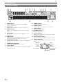
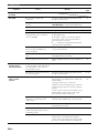
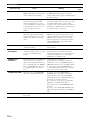
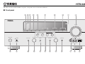
A ZONE2 ON/OFF
Switches the zone function on and off (page 63).
B HDMI THROUGH
Lights up in the following cases while this unit is on standby.
• when the HDMI control function is on
• when the HDMI signal standby-through function is currently
working
C ZONE2 CONTROL
Enables operation of a receiver set in Zone2, including input
source switching, volume control and tuner operation, with the
main amplifier or remote control after this key is pressed
(page 63).
D INFO
Changes information (input, DSP program, audio decoder, etc)
displayed on the front panel display (page 25).
E MEMORY
Registers FM/AM stations as preset stations (page 31) or XM/
SIRIUS channels as preset channels (pages 36 and 40).
F PRESET l / h
Selects an FM/AM preset station (page 31) or an XM/SIRIUS
preset channel (pages 36 and 40).
G FM/AM (CATEGORY l / h)
Change the tuner bands between FM and AM.
Select a channel category for a XM/SIRIUS.
H TUNING/CH l / h
Changes FM/AM frequencies or XM/SIRIUS tuner channels.
I Front panel display
Displays information on this unit (page 6).
J VOLUME control
Controls the volume of this unit (page 23).
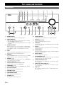
K MAIN ZONE ON/OFF
Turns this unit on and off (page 19).
L PHONES jack
For plugging headphones (page 25).
M TONE CONTROL
Adjusts high-frequency/low-frequency output of speakers
(page 24).
N PROGRAM selector
Changes sound field programs (page 26).
O STRAIGHT
Toggles between the selected sound field program and straight
decode mode (page 29).
P SCENE
Switches between linked sets of input sources and sound field
programs (page 23).
Q PURE DIRECT
Changes mode to Pure Direct mode (page 24). This key lights up
when Pure Direct mode is on.
R INPUT selector
Selects an input source (page 23).
S OPTIMIZER MIC jack
For connecting the supplied optimizer microphone and adjusting
output characteristics of speakers (page 20).
T VIDEO (VIDEO AUX) jack
For connecting the video output cable of a camcorder or game
console (page 18).
U AUDIO L/R (VIDEO AUX) jack
For connecting the audio output cable of a camcorder or game
console (page 18).
V USB port
For connecting a USB memory device or USB portable audio
player (page 18)
Part names and functions
Front panel
MAIN
ZONE
ON/OFF
PHONES
SILENT
CINEMA
TONE
CONTROL
PROGRAM
STRAIGHT
PURE DIRECT
INPUT
OPTIMIZER
MIC
VIDEO
AUDIO
THROUGH
VIDEO
AUX
USB
VOLUME
HDMI
EFFECT
BD/DVD
TV
CD
RADIO
SCENE
ZONE2
ON/OFF
INFO
MEMORY
ZONE2
CONTROL
PRESET
l
h
l
h
l
h
CATEGORY
FM AM
TUNING/CH
KNQMO R
ABC D E F G H I J
SULPTV

5 En
Part names and functions
English
INTRODUCTION
ADDITIONAL
INFORMATION APPENDIX
PREPARATION
BASIC
OPERATION
ADVANCED
OPERATION
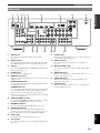
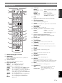
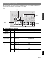
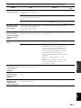
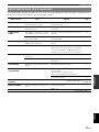
a SIRIUS jack
For connecting a SiriusConnect tuner (sold separately)
(page 38).
b DOCK terminal
For connecting an optional Yamaha iPod universal dock (YDS-
11) or Bluetooth wireless audio receiver (YBA-10) (page 17).
c XM jack
For connecting XM Mini-Tuner in XM Mini-Tuner Home Dock
(sold separately) (page 34).
d PHONO jacks
For connecting a turntable (page 15).
e MONITOR OUT jacks
Outputs visual signals from this unit to a video monitor, such as
a TV (page 14).
REMOTE IN/OUT jacks
For connecting an external component that supports the remote
control function (page 17).
TRIGGER OUT jack
For connecting an external terminal with a trigger input terminal
to operate it linked with operation of this unit. For example,
when an electric screen that supports a trigger input is
connected, it opens and closes linked with operation of an input
source selected in this unit.
f HDMI OUT/HDMI 1-4 jacks
For connecting an HDMI-compatible video monitor or external
components for HDMI inputs 1-4 (pages 14 and 15).
g ANTENNA terminals
For connecting supplied FM and AM antennas (page 18).
h SPEAKERS terminals
For connecting front, center, surround and surround back
speakers (page 11). Connect the presence speakers (page 11) or
the speakers for Zone2 (page 62) to EXTRA SP terminals.
i Power cable
Connect this cable to an AC wall outlet (page 19).
j AV 1-6 jacks
For connecting external components for audio/visual inputs 1-6
(page 15).
k AV OUT jacks
Outputs audio/visual signals from a selected analog input source
to an external component (page 15).
l AUDIO 1/2 jacks
For connecting external components for audio inputs 1-2
(page 15).
m MULTI CH INPUT jacks
For connecting a player that supports a multi-channel output
(page 16).
n AUDIO OUT jacks
Outputs audio signals from a selected analog input source to an
external component (page 15).
o ZONE2 OUT jacks
Outputs sound of this unit to an external amplifier set in a
different zone (page 62).
p PRE OUT jacks
Outputs multi-channel signals from up to 7.1 channels to an
external amplifier (page 17).
Rear panel
DOCK
PHONO
COMPONENT
VIDEO
PR
PB
Y
OPTICAL
(
TV
)
A
V
1
AV 2
COAXIAL
AV 3
(
CD
)
COAXIAL
OPTICAL
AV 4
AV 5
AV 6
AV
OUT
AUDIO1
AUDIO2
FRONT
SURROUND
SUR.BACK
SUBWOOFER
MULTI CH INPUT
AUDIO
OUT
ZONE2
OUT
FRONT
SURROUND
SUR. BACK SUBWOOFER
PRE OUT
CENTER
SINGLE
VIDEO
GND
HDMI OUT
ANTENNA
UNBAL.
FM
HD Radio
GND
AM
HDMI 1
(
BD/DVD
)
HDMI 2
HDMI 3
HDMI 4
VIDEO
IN
OUT
MONITOR OUT
SPEAKERS
TRIGGER OUT
12V
0.1A MAX.
FRONT
CENTER
SINGLE
CLASS 2 WIRING
SURROUND
SURROUND BACK/
BI-AMP
EXTRA SP
ZONE2/PRESENCE
12
CENTER
PR
PB
Y
REMOTE
COMPONENT
VIDEO
SIRIUS
XM
bca
jklmno p
de f g h i

6 En
Part names and functions
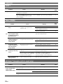
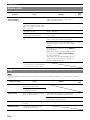
a HDMI indicator
Lights up during normal communication when HDMI is
selected as an input source.
b XM indicator
Lights up when an XM tuner is selected as an input source.
c SIRIUS indicator
Lights up when a SiriusConnect tuner is selected as an input
source.
d HD indicator
Lights up when this unit is tuned into the HD Radio reception
band (page 32).
e TAG indicator
Lights up when the selected HR Radio program (or song being
played) supports the iTunes Tagging feature (page 32).
f CINEMA DSP indicator
Lights up when a sound field program that uses CINEMA DSP
is selected.
g CINEMA DSP 3D indicator
Lights up when CINEMA DSP 3D is activated.
h Tuner indicator
Lights up during receiving radio broadcast signals from an FM/
AM station (page 30).
i ZONE2 indicator
Lights up when Zone2 is turned on.
j SLEEP indicator
Lights up when the sleep timer is activated (page 47).
k MUTE indicator
Flashes when audio is muted.
l VOLUME indicator
Displays volume levels.
m Cursor indicators
Light up if corresponding cursors on the remote control are
available for operations.
n Multi information display
Displays menu items and settings for the current operation.
o Speaker indicators
Indicate speaker terminals from which signals are currently
output.
Front panel display
STEREO
SLEEP
TAG
VOL.
TUNED
PL PR
SW
C
LR
SL SR
SBL SB SBR
MUTE
SIRIUS
XM
3
ZONE
2
HD
ab gfdecjlihk
mn om
SW
C
LR
SL SR
SBL SB SBR
PL PR
Subwoofer
Front L
Surround L
Surround back L
Center
Front R
Surround R
Surround back R
Surround back
Presence L Presence R

7 En
Part names and functions
English
INTRODUCTION
ADDITIONAL
INFORMATION APPENDIX
PREPARATION
BASIC
OPERATION
ADVANCED
OPERATION
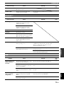
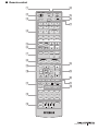
a Remote control signal transmitter
Transmits infrared signals.
b MAIN/ZONE2
Switches amplifiers (Main or Zone2) to be operated by the
remote control (page 63).
c SOURCE POWER
Switches an external component on and off.
d Input selection keys
e Tuner keys
f INFO
Changes the information shown on the front panel display
(page 25).
g Sound selection keys
Selects sound field programs (page 26).
h SCENE
Switches between linked sets of input sources and sound field
programs (page 23).
i ON SCREEN
Displays the GUI screen (page 24).
k External component operation keys
Operate recording, playback etc. of external components
(page 64).
l Numeric keys
Enter numbers.
m TV control keys
Enables operations of a TV or a projector (page 64).
n TRANSMIT
Lights up when a signal is output from the remote control.
o CODE SET
Sets remote control codes for external component operations
(page 64).
p POWER
Switches this unit on and standby (page 19).
q SLEEP
Switches the sleep timer operations (page 47).
r OPTION
Displays the Option menu (page 48).
s VOLUME +/–
Adjust the volume of this unit (page 23).
t DISPLAY
Displays the play information on the video monitor.
When an iPod is connected: Changes the operation mode of the
iPod connected to the Yamaha iPod universal dock (page 43).
u MUTE
Turns the mute function on and off (page 24).
v HD Radio keys
Remote control
HDMI 1-4
Selects HDMI inputs 1 through 4.
AV 1-6
Selects AV inputs 1 through 6.
AUDIO 1/2
Selects AUDIO inputs 1 and 2.
V-AUX
Selects a signal input from the VIDEO AUX jacks.
PHONO
Selects a signal input from the PHONO jacks.
USB
Selects a USB device connected to the USB port.
DOCK
Selects a Yamaha iPod universal dock/Bluetooth
wireless audio receiver connected to the DOCK terminal.
TUNER
Selects the FM/AM tuner.
SIRIUS
Selects a SiriusConnect tuner as an input source.
XM
Selects an XM tuner as an input source.
MULTI
Selects a signal input from the MULTI CH
INPUT jacks.
MAIN
POWER
1234
1256
1234
7856
90
10
1234
POWER
SOURCE
V-AUX
PHONO
USB DOCK
MULTI
XM
SIRIUS
TUNER
FM
MOVIE
BD
DVD
TOP
MENU
MUSIC
SCENE
TV
CD
OPTIONON SCREEN
RETURN
REC
ENT
POWER
TV
TV VOL
INPUT
MUTE
TV CH
ENTER
VOLUME
DISPLAY
MUTE
MENU
RADIO
STEREO
ENHANCER SUR. DECODE
PURE DIRECT
STRAIGHT
INFO
MEMORY
AM
CATEGORY
PRESET
TUN./CH
SLEEP
HDMI
AV
AUDIO
ZONE2
TRANSMIT
CODE SET
TAG PRG SELECT
a
c
p
q
d
e
g
h
i
r
s
t
u
v
k
l
m
b
o
n
j
f
FM/AM
Switches a band between FM and AM.
(CATEGORY l / h)
Select a channel category for XM/
SIRIUS.
MEMORY
Presets radio stations.
PRESET k / n
Selects a preset station.
TUN./CH k / n
Changes FM/AM frequencies or
XM/SIRIUS tuner channels.
j Cursors k / n / l / h
Select menu items or change
settings.
ENTER
Confirms a selected item.
RETURN
Returns to the previous screen or
ends the menu display.
TAG
Stores “tag” data to the iPod or internal
memory of this unit (page 32).
PRG SELECT
Selects an HD Radio audio program
(page 32).

8 En
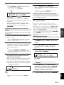
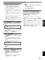
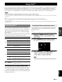
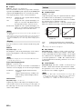
When you use this product for the first time, perform setup following the steps below. See the related pages for details on
operations and settings.
Prepare speakers, DVD player, cables, and other items
necessary for setup.
For example, prepare the following items for setting up a
7.1-channel sound system.
y
• Prepare two magnetically shielded speakers (for front). The priority of
the requirement of other speakers is as follows:
1 Two surround speakers
2 One center speaker
3 One (or two) surround back speaker(s)
• If your video monitor is a CRT, we recommend that you use magnetically
shielded speakers.
• Video and audio cables are unnecessary if you use HDMI cables.
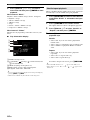
Place your speakers in the room and connect them to this
unit.
y
• This unit has a YPAO (Yamaha Parametric Room Acoustic Optimizer)
that automatically optimizes this unit based on room acoustic
characteristics (audio characteristics of the speakers, speaker positions,
and room acoustics, etc.).
You can enjoy good balanced sound without special knowledge by using
the YPAO technology (☞P. 20).
Connect your TV, DVD player, or other components.
Connect the power cable and turn on this unit.
Select the component connected in step 3 as an input
source and start playback.
y
• This unit supports the SCENE function (page 23) that changes the input
source and sound field program at one time. Four scenes are preset for
different purposes for Blu-ray disc, DVD and CD, and you can select
from a scene from those just by pressing a remote control key.
Quick start guide
Step 1: Prepare items for setup
Requirements qty.
Speakers Front speaker 2
Center speaker 1
Surround speaker 2
Surround back
speaker
2
Active subwoofer 1
Speaker cable 7
Subwoofer cable 1
Reproduction component such as DVD player 1
Video monitor such as TV 1
Video cable or HDMI cable 2
Audio cable 2
Front right speaker
Subwoofer
Surround left speaker
Surround right speaker
Front left
speaker
Video monitor
Center
speaker
Components
(such as DVD player)
Surround Back
right speaker
Surround Back
left speaker
Step 2: Set up your speakers
• Placing speakers ☞P. 1 0
• Connecting speakers ☞P. 1 1
Step 3: Connect your components
• Connecting a TV monitor or projector ☞P. 1 4
• Connecting other components ☞P. 1 5
• Connecting a multi-format player or an
external decoder ☞P. 1 6
• Connecting an external amplifier ☞P. 1 7
• Connecting a USB storage device ☞P. 1 8
• Connecting a Yamaha iPod universal dock or
Bluetooth wireless audio receiver ☞P. 1 7
• Connecting the FM and AM antennas ☞P. 1 8
• Connecting an XM Mini-Tuner Home Dock ☞P. 3 4
• Connecting a SiriusConnect tuner ☞P. 3 8
Step 4: Turn on the power
• Connecting the power cable ☞P. 1 9
• Turning this unit on and off ☞P. 1 9
Step 5: Select the input source and start
playback
• Basic procedure ☞P. 2 3
• Selecting sound field programs ☞P. 2 6

9 En
English
INTRODUCTION
ADDITIONAL
INFORMATION APPENDIX
PREPARATION
BASIC
OPERATION
ADVANCED
OPERATION
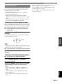
PREPARATION
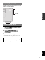
1 Take off the battery compartment cover.
2 Insert the two supplied batteries (AAA, R03,
UM-4) according to the polarity markings (+
and –) on the inside of the battery
compartment.
3 Snap the battery compartment cover back
into place.
Notes
• Change all batteries if you notice the following conditions:
– the operation range of the remote control narrows
– the transmit indicator does not flash or is dim
• Do not use old batteries together with new ones.
This may shorten the life of the new batteries or cause old batteries
to leak.
• Do not use different types of batteries (such as alkaline and
manganese batteries) together. Specification of batteries may be
different even though they look the same.
• If you find leaking batteries, discard the batteries immediately,
taking care not to touch the leaked material. If the leaked material
comes into contact with your skin or gets into your eyes or mouth,
rinse it away immediately and consult a doctor. Clean the battery
compartment thoroughly before installing new batteries.
• Dispose of the old batteries correctly in accordance with your local
regulations.
• If the remote control is without batteries for more than 2 minutes,
or if exhausted batteries remain in the remote control, the contents
of the memory may be cleared. In such a case, install new batteries
and set the remote control code.
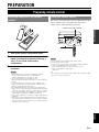
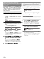
The remote control transmits a directional infrared ray. Be
sure to aim the remote control directly at the remote
control sensor on this unit during operation.
Notes
• Do not spill water or other liquids on the remote control.
• Do not drop the remote control.
• Do not leave or store the remote control in the following conditions:
– places of high humidity, such as near a bath
– places of high temperatures, such as near a heater or stove
– places of extremely low temperatures
– dusty places
y
• You can operate external components with this remote control by setting
the remote control code (page 64).
Preparing remote control
Installing batteries in the remote
control
1
3
2
Using the remote control
30 30
Remote control sensor window
within 6 m (20 ft)

10 En
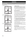
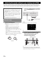
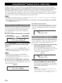
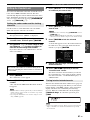
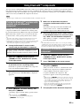
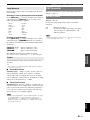
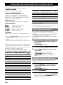
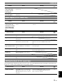
This unit supports up to 7.1-channel surround. We recommended the following speaker layout in order to obtain the
optimum surround effect.
7.1-channel speaker layout
6.1-channel speaker layout
5.1-channel speaker layout
■ Front left and right speakers (FL and FR)
The front speakers are used for the front channel sounds
(stereo sound) and effect sounds. Place these speakers at
an equal distance from the ideal listening position. When
using a screen, the appropriate top positions of the
speakers are about 1/4 of the screen from the bottom.
■ Center speaker (C)
The center speaker is for the center channel sounds
(dialog, vocals, etc.). Place it halfway between the left and
right speakers. When using a TV, place the speaker just
above or just under the center of the TV with the front
surfaces of the TV and the speaker aligned. When using a
screen, place it just under the center of the screen.
■ Surround left and right speakers (SL and SR)
The surround speakers are used for effect and surround
sounds. Place them at the rear left and rear right facing the
listening position. To obtain a natural sound flow in the
5.1-channel speaker layout, place them slightly further
back than in the 7.1-channel speaker layout.
■ Surround back left and right speakers (SBL
and SBR) / Surround back speaker (SB)
The surround back left and right speakers are used for rear
effect sounds. Place them at the rear of the room facing the
listening position at least 30 cm (1 ft) away from each
other, ideally at the same distance as that between the
front left and right speakers.
In the 6.1-channel speaker layout, surround back left and
right channel sound signals are mixed down and output
from the single surround back speaker.
In the 5.1-channel speaker layout, surround back left and
right channel sound signals are output from the surround
left and right speakers.
■ Subwoofer (SW)
The subwoofer speaker is used for bass sounds and low-
frequency effect (LFE) sounds included in Dolby Digital
and DTS signals. Use a subwoofer with a built-in
amplifier, such as the Yamaha Active Servo Processing
Subwoofer System. Place it exterior to the front left and
right speakers facing slightly inward to reduce reflections
from a wall.
Connections
Placing speakers
60˚
30˚
SBR
SBL
FL
FR
C
SL
SR
SR
80˚
SL
SW
SW
30 cm (12 in) or more
60˚
30˚
SB
FL
FR
C
SL
SR
SR
80˚
SL
SW
SW
60˚
30˚
FL
FR
C
SL
SR
SR
80˚
SL
SW
SW
Speaker channels

11 En
Connections
English
INTRODUCTION
ADDITIONAL
INFORMATION APPENDIX
PREPARATION
BASIC
OPERATION
ADVANCED
OPERATION
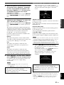
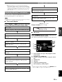
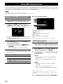
■ Presence left and right speakers (PL and PR)
The presence speakers supplement the sound from the
front speakers with extra ambient effects produced by the
sound field programs (page 26). We recommend that you
use the presence speakers especially for the CINEMA
DSP sound field programs. To use the presence speakers,
connect the speakers to EXTRA SP terminals and then set
“Extra Speaker Assignment” to “Presence” (page 57).
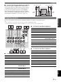
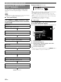
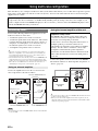
Connect your speakers to the respective terminals as follows, according to your speaker layout.
y
• Connect optional presence speakers or Zone2 speakers (page 62) to the EXTRA SP terminals.
• You can connect up to two subwoofers. When two subwoofers are connected, the same sound is output from them.
■ 7.1-channel (with presence speakers)
■ 6.1-channel (with Zone2 speakers)
■ 5.1-channel (with Zone2 speakers)
FR
PRPL
C
FL
0.5 to 1 m (1 to 3 ft)0.5 to 1 m (1 to 3 ft)
1.8 m
(6 ft)
1.8 m
(6 ft)
Connecting speakers
Speakers Jacks on this unit
a Front speaker L FRONT (L)
b Front speaker R FRONT (R)
c Center speaker CENTER
d Surround speaker L SURROUND (L)
e Surround speaker R SURROUND (R)
f Surround back speaker L SURROUND
BACK/BI-AMP (L)
g Surround back speaker R SURROUND
BACK/BI-AMP (R)
h Subwoofer 1 SUBWOOFER 1
i Subwoofer 2 (optional) SUBWOOFER 2
j Presence speaker L (optional) EXTRA SP (L)
k Presence speaker R (optional) EXTRA SP (R)
SUBWOOFER
SPEAKERS
FRONT
CENTER
SINGLE
CLASS 2 WIRING
SURROUND
SURROUND BACK/
BI-AMP
EXTRA SP
ZONE2/PRESENCE
12
SU
R.BA
CK
SUBWOOFER
H
INP
U
T
AUDI
O
OUT
ZONE
2
O
U
T
FR
O
N
T
SU
RR
OU
ND
SU
R. BA
CK
P
RE OUT
C
ENTE
R
S
IN
G
LE
A
NTENN
A
UNBAL.
FM
H
D Rad
io
G
N
D
AM
HDMI
3
HDMI
4
T
2V
MAX.
C
ENTER
E
c
g f
h i
e d
b a
k j
Speakers Jacks on this unit
a Front speaker L FRONT (L)
b Front speaker R FRONT (R)
c Center speaker CENTER
d Surround speaker L SURROUND (L)
e Surround speaker R SURROUND (R)
f Surround back speaker SURROUND
BACK/BI-AMP (SINGLE)
h Subwoofer 1 SUBWOOFER 1
i Subwoofer 2 (optional) SUBWOOFER 2
j Zone2 speaker L (optional) EXTRA SP (L)
k Zone2 speaker R (optional) EXTRA SP (R)
Speakers Jacks on this unit
a Front speaker L FRONT (L)
b Front speaker R FRONT (R)
c Center speaker CENTER
d Surround speaker L SURROUND (L)
e Surround speaker R SURROUND (R)
h Subwoofer 1 SUBWOOFER 1
i Subwoofer 2 (optional) SUBWOOFER 2
j Zone2 speaker L (optional) EXTRA SP (L)
k Zone2 speaker R (optional) EXTRA SP (R)

12 En
Connections
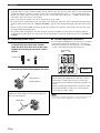
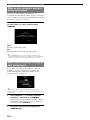
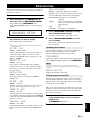
■ Connecting speaker cables
1 Remove approximately 10 mm (0.4 in) of
insulation from the end of each speaker
cable and then twist bare wires of the cable
together so that they will not cause a short
circuits.
2 Loosen the knob, insert the twisted bare
wires into the hole and then tighten the knob.
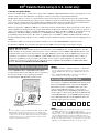
■ Using bi-amplification connections
You can make bi-amplification connections to one speaker
system which supports bi-amplification connection as
shown below. To activate the connections, set “BI-AMP”
to “ON” in the advanced setup menu (page 65).
Note
• You cannot use surround back speakers or extra speakers (presence and
Zone2 speakers) when bi-amplification connections are made.
Caution
• A speaker cable is a pair of insulated cables running side by side in general. One of the cables is colored differently
or striped to indicate a polarity. Connect one end of the colored/striped cable to the “+” (red) terminal of this unit
and the other end to that of your speaker, and connect one end of the other cable to the “–” (black) terminal of this
unit and the other end to that of your speaker.
• Before connecting the speakers, be sure to disconnect the power cable.
• Do not let the bare speaker wires touch each other or any metal part of this unit. This could damage this unit and/or
speakers. If the circuit shorts out, “CHECK SP WIRES!” appears on the front panel display when this unit is turned
on.
• If images on the monitor (CRT) are distorted, place the speakers away from the video monitor. If it does not work,
use magnetically shielded speakers.
• Use speakers with an impedance of 6-ohm or larger. Set speaker impedance in the advanced setup menu before
connecting the speakers (page 65). You can also use 4-ohm speakers as the front speakers when you set “SP IMP.” to
“6ΩMIN”.
Connecting the banana plug
Tighten the knob and then insert the banana plug into
the end of the terminal.
10 mm (0.4 in)
1
2
3
Red: positive (+)
Black: negative (–)
Banana plug
Caution
Before making bi-amplification connections, remove
any brackets or cables that connect a woofer with a
tweeter. Refer to the instruction manuals of speakers for
details.
When not making bi-amplification connections, make
sure that the brackets or cables are connected before
connecting the speaker cables.
SURROUND BACK/
BI-AMP
FRONT
Front speakers
Right Left
This unit

13 En
Connections
English
INTRODUCTION
ADDITIONAL
INFORMATION APPENDIX
PREPARATION
BASIC
OPERATION
ADVANCED
OPERATION
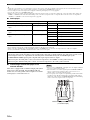
This unit has the following input and output jacks. Use jacks and cables appropriate for components that you are
connecting.
■ Audio jacks
■ Video jacks
■ Video/audio jacks
y
• We recommend that you use a commercially available 19-pin HDMI
cable no longer than 5 meters (16 feet) with the HDMI logo printed on it.
• Use a conversion cable (HDMI jack ↔ DVI-D jack) to connect this unit
to other DVI components.
• You can check the potential problem about the HDMI connection
(page 49).
Information on jacks and cable plugs
Jack and cables Description
Analog audio jacks To transmit conventional analog
stereo audio signals. Use stereo pin
cables. Connect red plugs to red
jacks (R) and white plugs to white
jacks (L).
COAXIAL jacks To transmit coaxial digital audio
signals. Use pin cables for digital
audio signals.
OPTICAL jacks To transmit optical digital audio
signals. Use optical fiber cables for
optical digital audio signals.
Jack and cables Description
VIDEO jacks To transmit conventional
composite video signals. Use video
pin cables.
COMPONENT VIDEO
jacks
To transmit component video
signals that include luminance (Y),
chrominance blue (PB) and
chrominance red (PR) components.
Use component video cables.
L
R
(white)
(red)
COAXIAL
C
(orange)
OPTICAL
O
VIDEO
V
(yellow)
PR
PB
Y
COMPONENT
VIDEO
P
B
Y
P
R
(red)
(blue)
(green)
Jack and cables Description
HDMI jacks To transmit digital video and
digital audio signals. Use HDMI
cables.
This unit automatically converts input video signals and
outputs the signals to the HDMI OUT jack and
MONITOR OUT (COMPONENT VIDEO and
VIDEO) jacks (video conversion).
HDMI
HDMI
HDMI
VIDEO
COMPONENT
VIDEO
Y
PB
PR
HDMI
VIDEO
COMPONENT
VIDEO
Y
PB
PR
Input Output
Through Converted

14 En
Connections
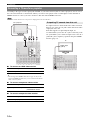
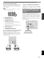
According to the types of video input jacks available on your video monitor (such as a TV or projector), choose one of
the connection methods as shown below. When you connect video players such as a DVD player to this unit with an
HDMI connection, connect your video monitor to this unit with an HDMI connection.
Note
• Make sure that this unit and other components are unplugged from the AC wall outlets.
■ To connect an HDMI video monitor
y
• This unit supports the HDMI control function (page 47). If your TV
supports the HDMI control function, you can control this unit with the
remote control of your TV.
■ To connect component video monitor
■ To connect composite video monitor
To output sound of a TV from this unit, make connection
between one of the AV 1-6 jacks of this unit and an audio
output jack of the TV.
If the TV supports an optical digital output, we
recommend that you use the AV 1 jack. Connecting to the
AV 1 jack allows you to switch an input source to the AV 1
jack with a just a single key operation using the SCENE
function (page 23).
Connecting a TV monitor or projector
Jacks on components Jacks on this unit
a HDMI input HDMI OUT
Jacks on components Jacks on this unit
b Component video output MONITOR OUT
(COMPONENT VIDEO)
Jacks on components Jacks on this unit
c Video input (composite) MONITOR OUT (VIDEO)
HDMI OUT
VIDEO
MO
NIT
O
R
OUT
P
R
P
B
Y
COMPONENT
VIDEO
PH
O
N
O
L
O
PTI
C
A
L
AV 4
AV
5
A
V 6
AV
OU
T
A
UDIO1
AUDI
O
2
FR
O
N
T
SU
RR
OU
N
D
S
UR.B
A
MU
LTI
C
H INP
U
GND
HDMI 1
(
BD
/
DV
D
)
HDMI 2
H
D
M
IN
O
U
T
T
RI
GG
ER
O
U
T
12V
0
.1
A
MAX.
R
EM
O
T
E
HDMI
V
a
c
b
P
B
YP
R
TV, or projector
Outputting TV sounds from this unit
OPTICAL
(
TV
)
AV
1
P
R
P
B
Y
AV
2
CO
AXIA
L
A
V 3
(
C
D
)
CO
AXIA
L
O
PTI
C
AL
AV
4
AV
5
AV
6
AV
OUT
AUDIO1
A
U
D
VIDE
O
GND
P
R
P
B
Y
O
Digital output
(optical)
TV

15 En
Connections
English
INTRODUCTION
ADDITIONAL
INFORMATION APPENDIX
PREPARATION
BASIC
OPERATION
ADVANCED
OPERATION
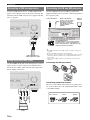
This unit has input and output terminals for respective input and output sources. You can reproduce sound and movies
from input sources selected with the front panel display or remote control.
Note
• Make sure that this unit and other components are unplugged from the AC wall outlets.
■ Audio and video player / Set-top box
Connecting other components
Output jacks on the connected external component Input sources/jacks of this unit
External
component
Signal Output jack Input source Input jack
External component
with HDMI output
Audio/Video HDMI output HDMI 1 (BD/DVD) HDMI 1
HDMI 2 HDMI 2
HDMI 3 HDMI 3
HDMI 4 HDMI 4
External component
with component video
output
Audio Optical digital output AV 1 (TV) OPTICAL
Video Component video COMPONENT VIDEO
Audio Coaxial digital output AV 2 COAXIAL
Video Component video output COMPONENT VIDEO
External component
with composite video
output
Audio Coaxial digital output AV 3 (CD) COAXIAL
Video Composite output VIDEO
Audio Optical digital output AV 4 OPTICAL
Video Composite output VIDEO
Audio Analog audio output AV 5 Analog audio
Video Composite output VIDEO
Audio Analog audio output AV 6 Analog audio
Video Composite output VIDEO
PHONO
COMPONENT
VIDEO
P
R
P
B
Y
OPTICAL
(
TV
)
AV
1
AV 2
COAXIAL
AV 3
(
CD
)
COAXIAL
OPTICAL
AV 4
AV 5
AV 6
AV
OUT
AUDIO1
AUDIO2
FRONT
SURROUND
SUR.BACK
SUBWOOFER
MULTI CH INPUT
AUDIO
OUT
VIDEO
GND
HDMI 1
(
BD/DVD
)
HDMI 2 HDMI 3
HDMI 4
TRIGGER
OUT
CENTER
D
OCK
Z
O
O
H
DMI
OUT
V
IDE
O
IN
OU
T
MONITOR OU
T
TRIGGER OUT
1
2
V
0
.1A MAX
.
F
R
O
N
T
P
R
P
B
Y
R
EM
O
T
E
C
OMPONENT
VIDE
O
S
IRIU
S
XM
Audio / video input
(AV 1-6)
Audio / video output (AV OUT)
Audio input (AUDIO 1/2)
HDMI input
(HDMI 1-4)
Audio output
(AUDIO OUT)
Multi channel audio input (MULTI CH INPUT)
Audio input (PHONO)

16 En
Connections
y
• Input sources in parentheses are recommended to connect to the respective jacks. If your Yamaha component has the remote in/out terminal, you can
switch the input source to that component with a single key operation using the SCENE function (page 23).
• You can change the name of the input source displayed on the front panel display as necessary (page 61).
• See page 62 on how to use the ZONE2 OUT jacks.
• When you connect an external component with analog audio and component video (or composite) output jacks, connect the analog audio output to the
AUDIO 1 or AUDIO 2 jacks of this unit while making a video connection (component video or composite). Then select the video to be output when
“AUDIO 1” or “AUDIO 2” is selected as the input source (page 50).
■ Audio player
y
• We recommend connecting the coaxial digital output terminal of a CD player to the AV3 jack.
• When connecting a turntable with a low-output MC cartridge to the PHONO jacks, use an in-line boosting transformer or MC-head amplifier.
• Connect your turntable to the GND terminal of this unit to reduce noise in the signal.
■ Connecting a multi-format player or an
external decoder
This unit is equipped with 8 additional input jacks (Front
L/R, Center, Surround L/R, Surround Back L/R and
Subwoofer) for analog multi-channel input from a multi-
format player, external decoder, etc.
Notes
• When you select “MULTI CH” as the input source, the digital sound field
processor is automatically disabled.
• Since this unit does not redirect signals input at the MULTI CH INPUT
jacks to accommodate for missing speakers, connect at least a 5.1-
channel speaker system when using this feature.
• You can specify a video signal to be output during a multi-channel audio
reproduction (page 50). If your DVD player has analog multi-channel
output jacks, connect them to the MULTI CH INPUT jacks while making
a video connection (component video or composite).
Output jacks on the connected external component Input sources/jacks of this unit
External component Output jack Input source Input jack
External component with optical digital
output
Optical digital output AV 1 (TV) OPTICAL
AV 4 OPTICAL
External component with coaxial digital
output
Coaxial digital output AV 2 COAXIAL
AV 3 (CD) COAXIAL
External component with analog audio
output
Analog audio output AV 5 Analog audio
AV 6 Analog audio
AUDIO 1 Analog audio
AUDIO 2 Analog audio
Turntable Analog audio output PHONO Analog audio
About audio/video output terminals
Among the analog audio and analog video signals input to this unit via input terminals, the audio/video signals of the
selected input sources are output from the AV OUT jacks and AUDIO OUT jacks. An HDMI input signal,
COMPONENT VIDEO input signal or digital audio input signal cannot be output.
When using the AV OUT jacks: connect an external component to the VIDEO or analog audio terminal.
When using the AUDIO OUT jacks: connect an external component to the analog audio terminal.
FRONT
SURROUND
SUR.BACK
SUBWOOFER
MULTI CH INPUT
CENTER
LRLR RL
Surround
back out
Surround
out
Front out
Subwoofer out
Center out
Multi-format player or external decoder
(7.1-channel output)
La page charge ...
La page charge ...
La page charge ...
La page charge ...
La page charge ...
La page charge ...
La page charge ...
La page charge ...
La page charge ...
La page charge ...
La page charge ...
La page charge ...
La page charge ...
La page charge ...
La page charge ...
La page charge ...
La page charge ...
La page charge ...
La page charge ...
La page charge ...
La page charge ...
La page charge ...
La page charge ...
La page charge ...
La page charge ...
La page charge ...
La page charge ...
La page charge ...
La page charge ...
La page charge ...
La page charge ...
La page charge ...
La page charge ...
La page charge ...
La page charge ...
La page charge ...
La page charge ...
La page charge ...
La page charge ...
La page charge ...
La page charge ...
La page charge ...
La page charge ...
La page charge ...
La page charge ...
La page charge ...
La page charge ...
La page charge ...
La page charge ...
La page charge ...
La page charge ...
La page charge ...
La page charge ...
La page charge ...
La page charge ...
La page charge ...
La page charge ...
La page charge ...
La page charge ...
La page charge ...
La page charge ...
La page charge ...
La page charge ...
La page charge ...
La page charge ...
La page charge ...
La page charge ...
La page charge ...
La page charge ...
La page charge ...
La page charge ...
La page charge ...
La page charge ...
La page charge ...
La page charge ...
La page charge ...
La page charge ...
La page charge ...
La page charge ...
La page charge ...
La page charge ...
La page charge ...
-
 1
1
-
 2
2
-
 3
3
-
 4
4
-
 5
5
-
 6
6
-
 7
7
-
 8
8
-
 9
9
-
 10
10
-
 11
11
-
 12
12
-
 13
13
-
 14
14
-
 15
15
-
 16
16
-
 17
17
-
 18
18
-
 19
19
-
 20
20
-
 21
21
-
 22
22
-
 23
23
-
 24
24
-
 25
25
-
 26
26
-
 27
27
-
 28
28
-
 29
29
-
 30
30
-
 31
31
-
 32
32
-
 33
33
-
 34
34
-
 35
35
-
 36
36
-
 37
37
-
 38
38
-
 39
39
-
 40
40
-
 41
41
-
 42
42
-
 43
43
-
 44
44
-
 45
45
-
 46
46
-
 47
47
-
 48
48
-
 49
49
-
 50
50
-
 51
51
-
 52
52
-
 53
53
-
 54
54
-
 55
55
-
 56
56
-
 57
57
-
 58
58
-
 59
59
-
 60
60
-
 61
61
-
 62
62
-
 63
63
-
 64
64
-
 65
65
-
 66
66
-
 67
67
-
 68
68
-
 69
69
-
 70
70
-
 71
71
-
 72
72
-
 73
73
-
 74
74
-
 75
75
-
 76
76
-
 77
77
-
 78
78
-
 79
79
-
 80
80
-
 81
81
-
 82
82
-
 83
83
-
 84
84
-
 85
85
-
 86
86
-
 87
87
-
 88
88
-
 89
89
-
 90
90
-
 91
91
-
 92
92
-
 93
93
-
 94
94
-
 95
95
-
 96
96
-
 97
97
-
 98
98
-
 99
99
-
 100
100
-
 101
101
-
 102
102


Yamaha HTR-6280 Le manuel du propriétaire
- Catégorie
- Récepteurs AV
- Taper
- Le manuel du propriétaire
dans d''autres langues
- italiano: Yamaha HTR-6280 Manuale del proprietario
- English: Yamaha HTR-6280 Owner's manual
- español: Yamaha HTR-6280 El manual del propietario
- Deutsch: Yamaha HTR-6280 Bedienungsanleitung
- русский: Yamaha HTR-6280 Инструкция по применению
- Nederlands: Yamaha HTR-6280 de handleiding
- português: Yamaha HTR-6280 Manual do proprietário
- dansk: Yamaha HTR-6280 Brugervejledning
- polski: Yamaha HTR-6280 Instrukcja obsługi
- čeština: Yamaha HTR-6280 Návod k obsluze
- svenska: Yamaha HTR-6280 Bruksanvisning
- Türkçe: Yamaha HTR-6280 El kitabı
- suomi: Yamaha HTR-6280 Omistajan opas
- română: Yamaha HTR-6280 Manualul proprietarului
Documents connexes
-
Yamaha HTR-6250 Le manuel du propriétaire
-
Yamaha RXV465 - RX AV Receiver Le manuel du propriétaire
-
-
Yamaha RXV461BL Manuel utilisateur
-
-
Yamaha RX-V671 Le manuel du propriétaire
-
-
-
Yamaha RX-V863 Le manuel du propriétaire
-
Autres documents
-
Sherwood S9 SOUND PANORAMA Operating Instructions Manual
-
 Onn 100002460 Manuel utilisateur
-
Rotel RX-1052 Le manuel du propriétaire
-
-
 Vanatoo TRANSPARENT ZERO Le manuel du propriétaire
-
Marantz MM7055 Manuel utilisateur
-
Boston Acoustics SoundWare XS Digital Cinema Le manuel du propriétaire
-
Pioneer SX-LX70SW Manuel utilisateur
-
EDIFIER E255 Manuel utilisateur
-
HK Audio Polar 10 Manuel utilisateur

