Orbit WaterMaster 57692 Installation Manual & Users Manual
- Taper
- Installation Manual & Users Manual

MODELS
57674, 57676, 57679, 57672,
57694, 57696, 57699, 57692,
57662, 57664, 57666, 57669,
57682, 57684, 57686, 57689,
57962, 57964, 57966, 57969,
57972, 57974, 57976, 57979,
94102, 94104, 94106, 94109,
94112, 94114, 94116, 94119
WT 12/13
versions
Installation Manual / User’s Manual
Sprinkler Timers by Orbit
®
Manuel d’installation / Manuel d’utilisation
Programmateurs d’arrosage par Orbit
®
Manual de Instalación / Manual del usuario
Programadores para sistemas de aspersión Orbit
®
Manuale d’installazione / Manuale d’uso
Programmatore per irrigazione Orbit
®
Installationshandbuch / Benutzerhandbuch
Orbit
®
Steuergerät für Bewässerungssysteme
A
B
1 2 3 4 5 6 7 8 9 10 11 12 PUMP COM1 COM2
ZONE
DURATION
CYCLE
START
TIMES
DAY OF
WEEK
CYCLE
START
TIMES
ZONE
DURATION
WATERING
INTERVAL
INTERVAL
ODD
EVEN
MTWT F SS 2nd
ENTER
NEXT
1
2
3
4
CLEAR
MANUAL
TIME/DATE
AUTO
123456789101112
OFF
RAIN DELAY
RESET
ZONE
PROGRAM
CYCLE
START TIMES
DAY
MONTH
YEAR
WTM210729 57962-24 rE.qx 6/11/01 1:43 PM Page A

Introduction...........................................................................1
Getting Started .......................................................................2
Programming..........................................................................3
Manual Operation ..................................................................4
Installation of Indoor Mount Timer........................................6
Installation of Outdoor Mount Timer.....................................7
Installing Valves, Pump Starts and Master Valves....................8
Other Quality Products and Accessories.....................................9
Trouble Shooting......................................................................10
Introduction ....................................11
Pour commencer .................................12
Programmation ..................................13
Manuel d’utilisation...............................15
Installation du programmateur à montage intérieur .........17
Installation du programmateur à montage extérieur .........18
Installation des vannes, des relais de démarrage
de pompe et des vannes principales .......................19
Autres produits et accessoires de qualité ..................20
Dépannage .......................................21
Introducción ........................................................................22
Para comenzar......................................................................23
Programación .......................................................................24
Operación manual................................................................26
Instalación de un programador de montaje interior ............27
Instalación de un programador de montaje exterior.............28
Instalación de las válvulas, el encendido
de la bomba y las válvulas principales......................................30
Otros productos y accesorios de calidad ..................................31
Resolución de problemas..........................................................32
Introduzione ........................................................................33
Preparazione per l'uso ..........................................................34
Programmazione ..................................................................35
Funzionamento manuale......................................................37
Installazione del programmatore-montaggio interno ............38
Installazione del programmatore-montaggio esterno ............39
Installazione delle valvole, pompa d’avviamento
o valvola principale..................................................................41
Altri prodotti ed accessori di qualità ........................................42
Individuazione ed eliminazione delle anomalie........................43
Einführung...........................................................................44
Anfang..................................................................................45
Programmierung ..................................................................46
Manueller und halbautomatischer Betriebsablauf .................47
Inneninstallation des Steuergerätes...................................... 49
Außeninstallation des Steuergerätes .................................... 50
Installation der Ventile, Pumpenanlasser und Hauptventile..51
Sonstige Qualitätsprodukte und Zubehör.................................52
Fehlerbehebung .......................................................................53
DEUTSCH
ITALIANO
ESPAÑOL
FRANÇAIS
ENGLISH
TABLE OF CONTENTS
WTM210729 57962-24 rE.qx 6/11/01 1:43 PM Page B

Thank you for selecting an Orbit® sprinkler Timer. Orbit® designers have
combined the simplicity of mechanical switches with the accuracy of digital
electronics to give you a Timer that is both easy to program and extremely
versatile. The Orbit
®
Timer provides convenience and flexibility, letting you
run a fully automatic, semi-automatic, or a manual watering program for all
your watering needs.
Please read this manual completely before you begin to program and use the
controller. A few of the most notable design features include:
At-a-Glance Simplicity
By turning the rotary dial to one of nine settings you can review program-
ming or easily make changes.
Arm Chair Programmable
By inserting two AA alkaline batteries you can program the Timer prior to
installing it in its permanent location.
Fail-Safe Program / Non-Volatile Program Memory
If the Timer loses AC power, the existing program will not be lost. After the
AC power returns, the Timer will recall the last program into memory and
there will be no need to re-program. If both the AC power is lost and the
batteries are dead or missing, the user will only need to reset the time and
date; all other program settings are held in non-volatile memory, and there is
no need for re-entry.
Fuse
Red flashing LED indicates blown fuse. The 0.75 amp slow-blow fuse pro-
vides circuit protection. For replacement, use WaterMaster 0.75 amp fuse or
equivalent.
Lexan Language Covers
Available in English, French, Spanish, Italian, German.
FIGURE 1: Location of Controls on the Timer
1. Digital Display
A large LCD (Liquid Crystal Display) shows the time of day and indicates
many of the programming settings. The display is completely interactive
with all other controls.
2. Programming Keys
The Timer has seven push button keys for setup and program entry.
Working in conjunction with the rotary selector, the keys are used to set the
time of day, watering time, watering days, start times, and other functions.
3. Selector Dial
This large dial makes it easy to see which function is currently selected
and/or in which mode the Timer is set to operate.
4. Reset Button
The reset button clears the time, date and user-defined programming but does not
remove the factory installed fail-safe program. To prevent an accidental reset, the
button is recessed into the panel and must be pressed with a small pointed object
such as a pen or pencil tip.
Notable Programming Features
Two Watering Programs—Summary
The Timer gives you the option of using one or both of the independent pro-
grams. Note that each station can independently be set to either A or B or
both A and B programs.
Program–A
This program lets you schedule selected stations to water on specific days of
the week or to water every 2nd day. Program A repeats itself continuously in
successive weeks.
Program–B
Provides two options: One for odd or even day watering or for intervals rang-
ing from everyday to every 28th day. This feature is designed to meet the
growing needs and restrictions imposed by local governments and to con-
serve water. The Timer automatically calculates odd and even days (by date)
for each month and makes adjustments for leap years to provide true odd
and even watering through the year 2095.
Start-Time Stacking
The Timer has the intelligence to “stack” start times that overlap.
If you enter two or more start times that overlap (in the same or in different
programs), the Timer will not activate two stations at the same time. Instead,
the Timer activates the first station and then activates the next station(s) in
sequence after the first station finishes its preset watering duration.
The Timer will NOT stack to the next calendar day. This prevents the Timer
from violating an odd or even day watering schedule.
Manual and Semi-Automatic Modes
The Timer gives you a number of manual and semi-automatic modes for flexibility in
watering. You can override the Timer’s automatic programming in a variety of ways.
A
B
1
4
ZONE
DURATION
CYCLE
START
TIMES
DAY OF
WEEK
CYCLE
START
TIMES
ZONE
DURATION
WATERING
INTERVAL
INTERVAL
ODD
EVEN
MTWT FS S 2nd
1
2
3
4
TIME/DATE
AUTO
123456789101112
OFF
ZONE
PROGRAM
CYCLE
START TIMES
DAY
MONTH
YEAR
NEXT
CLEAR
MANUAL
RAIN DELAY
ENTER
RESET
3
2
ENGLISH
1
1
section
Introduction
WTM210729 57962-24 rE.qx 6/11/01 1:43 PM Page 1

Programming the Timer can be accomplished in just a few basic steps. Before
you begin programming, it is important to install the battery, set the time of
day and date, and establish a watering plan.
Install the Batteries
The Timer requires two AA batteries to maintain the time and date in case of
AC power loss. In a typical installation, fully charged batteries should provide
sufficient power for approximately one year of operation.
Remove the terminal cover.
Insert two AA batteries into the battery compartment.
Return the terminal cover to its closed position.
Weak or missing batteries can cause the time and date to be erased after a
power failure. If this happens, you will need to install fully charged batteries
and re-enter the time and date. All other program settings will be maintained
in non-volatile memory. The display will show "LO BAT" when it is time to
replace the battery.
Set the Time of Day and Date
If this is the first time the Timer has been programmed, you should press the
small recessed button labeled
RESET. Pressing RESET does not affect the factory
installed fail-safe program [See Figure 2].
FIGURE 2: Programming Keys
Tu rn the rotary dial to the TIME/DATE position [See Figure 3].
12:00 AM will appear in the display with three arrows pointing to the year,
month, and day.
Use the + and - keys to set the correct time of day. When the correct time
of day is reached, press the
ENTER key to lock in the time. To increase or
decrease more rapidly, hold down either the + or – keys until the display
goes into rapid advance mode.
A blinking cursor will appear below the arrow for the year, month, and
date when programming [See Figure 4].
Use the + and – keys to set the correct year, then press
ENTER.
Use the + and – keys to set the correct month, then press
ENTER.
Use the + and – keys to set the correct date, then press
ENTER.
FIGURE 3: LCD Display with Surrounding Information
FIGURE 4
Caution: If a watering schedule is not entered into the Timer, the factory installed
fail-safe program will turn on each station every day for 10 minutes.
To avoid accidental valve activation, either turn the rotary dial to
OFF or enter a
watering schedule.
Establish a Watering Schedule
To help you visualize how best to program the Timer, it might be helpful to
make a watering plan on paper. This will help you establish which days and
times you want to water.
▼▼▼▼
AM
▼
▼▼▼
▼▼▼▼▼▼ ▼▼▼▼▼▼
▼▼▼
▼
Cursor
5:00
INTERVAL
ODD
EVEN
M TWT F S S 2nd
1
2
3
4
123456789101112
ZONE
PROGRAM
CYCLE
START TIMES
DAY
MONTH
YEAR
AM
▼▼▼
12:00
NEXT
CLEAR
MANUAL
RAIN DELAY
ENTER
RESET
2
2
section
Getting Started
WTM210729 57962-24 rE.qx 6/11/01 1:43 PM Page 2

The Timer has two programs you can setup to control a variety of watering
schedules. Depending on your needs, you can use either or both programs.
Enter the Watering Schedule in Any Order
You have the option of entering your watering schedule in whatever order
you like. This feature makes it very easy to review and change your watering
schedule. Your settings can be changed at any time—while you’re setting up
the initial schedule or even after years of operation.
Start Times for Program A or B
Note: A start time is the time of day that the program begins watering the first station,
and all other stations in the program will then follow in sequence. There are not sepa-
rate start times for each station. Start times do not correspond to specific stations, but to
programs (A or B). If you enter more than one start time, all stations in the specified
program will water again (in sequence).
The way you set the cycle start time is the same for both programs. Turn
the rotary dial to the
CYCLE START TIMES position in the program that you
want to set. The display will show an A or B depending on which program
you have selected. The display will show —— : ——
and a blinking cursor in
CYCLE START 1 location [See Figure 5].
Set the time you want to begin watering for start time 1 using the
+ or – keys, then press the
ENTER key. The display will advance to START 2.
For additional start times, simply repeat this procedure by using the + and
– keys to enter the time and then press
ENTER
. Remember, Each start time
will activate all stations that are set to water in the specified program. There are
not separate start times for each station. Start times do not correspond to spe-
cific stations.
Up to four start times can be entered per program (A or B).
FIGURE 5: LCD Display with Start Time
Water Duration for Program A or B
Note: Both programs require watering durations to be programmed.
Tu rn the rotary dial to
ZONE DURATION position in either the A or B program.
The display will show which program you have selected with an "A" or "B"
and the - - cursor blinking at station "1" [See Figure 6].
FIGURE 6: Station Duration for Program A
You can set the watering duration from 1 to 99 minutes. Press and hold
the + key to advance the number of minutes, or use the - key to go in
reverse, then press
ENTER. When the minutes are set, “A” or “B” will
appear over station 1 and the cursor will advance to station 2 and begin
blinking.
Simply repeat these steps to set watering durations for all zones on this
program
To skip a station, press the
NEXT key.
To erase previously programmed watering durations, press the
CLEAR key.
Assigning Watering Days for Program A
Tu rn the rotary dial to DAY OF WEEK in program A. The display will show an
“A” and the cursor will blink under the days of week M, T, W, T, F, S, S
(Monday, Tuesday, etc.) [See Figure 7].
FIGURE 7: LCD Display with Watering Days
Press ENTER to activate watering on Monday. An arrow appears under M
and the cursor will advance to Tuesday (“T”), press
ENTER to activate water-
ing on this day. Repeat these steps for all days of the week.
To skip a day, press
NEXT.
To delete a previously entered day, press
CLEAR
If you want to water every second day, press the NEXT key to advance the
cursor to “2nd”, then press
ENTER.
Note: If you choose to water every 2nd day, you cannot set specific days of the
week for watering
Assigning Watering Intervals for Program B
Program B is used to water at specific intervals between days (1 to 28), or on
odd or even calender dates. The Timer has a leap-year compensator and will
ensure conformance to the odd and even schedule through the year 2095.
Tu rn the rotary dial to
WATERING INTERVAL. The cursor will blink to the left
of the word
INTERVAL [See Figure 8].
A
ZONE
DURATION
CYCLE
START
TIMES
DAY OF
WEEK
INTERVAL
ODD
EVEN
MTWT F SS 2nd
1
2
3
4
123456789101112
ZONE
PROGRAM
CYCLE
START TIMES
DAY
MONTH
YEAR
A
A
INTERVAL
ODD
EVEN
MTWT F SS 2nd
1
2
3
4
123456789101112
ZONE
PROGRAM
CYCLE
START TIMES
DAY
MONTH
YEAR
A
--.--
ZONE
DURATION
CYCLE
START
TIMES
DAY OF
WEEK
A
INTERVAL
ODD
EVEN
M TWT FSS 2nd
1
2
3
4
123456789101112
ZONE
PROGRAM
CYCLE
START TIMES
DAY
MONTH
YEAR
A
--.--
ZONE
DURATION
CYCLE
START
TIMES
DAY OF
WEEK
3
ENGLISH
3
section
Programming
WTM210729 57962-24 rE.qx 6/11/01 1:43 PM Page 3

FIGURE 8: LCD Display with Watering Interval
Press and hold the + or - keys to select the number of days between water-
ing. Example: If you want to water once every 10 days, set the interval at 10.
To activate the watering interval, press
ENTER.
Note: If an interval of “3” is entered today, the Timer will water for the first time
today, and then again every “3” days.
To select odd or even day watering, press
NEXT. The cursor will move to
either the odd or even setting, then press
ENTER.
To erase a schedule, press
CLEAR. To enter a new schedule, press NEXT.
Reviewing and Changing Your Program
The Orbit Timer lets you easily review a complete watering plan.
For example, to review Program-A watering start times, simply turn the
rotary dial to the
CYCLE START TIMES position in Program-A and check the times
that have been entered. Using the
NEXT key, you can advance through the
schedule without fear of disturbing any programming. If you want to change
the start times, watering days, or interval, simply follow the directions for
that program. After reviewing or changing a watering schedule, remember to
turn the rotary dial back to
AUTO.
Ready for Automatic Operation
After programming is complete, turn the rotary dial to AUTO [See Figure 9].
The Timer is now fully programmed and ready to use in the automatic mode.
In automatic mode, each program will operate sequentially, starting with
Program-A.
FIGURE 9: Ready for Automatic Operation
The Orbit Timer has the ability to override the automatic program without
disturbing the preset program.
Using the Semi-Automatic Mode
(All stations cycle once both A & B programs)
Tu rn the rotary dial to
AUTO, then press the MANUAL key. The display will
show “AB”, “MANUAL”, and “ALL” will be blinking [See Figure 10].
This indicates all stations will semi-automatically water for their assigned
durations in sequence.
To activate the assigned water durations in the A and B programs for each
station, press
ENTER.
FIGURE 10: Semi-Automatic Watering for Stations Assigned to A and B Programs
Note: Water durations assigned to station 1 in program A will water first, then
move to station 1 in program B before advancing to the second station and will con-
tinue alternating. Only those stations assigned a watering duration will water when
using the manual or semi-automatic mode [See Figure 11].
FIGURE 11: Semi-Automatic Watering Entered for A and B Programs, All Stations
(All stations cycle once, A program only)
To activate each stations assigned watering durations for the A program
only, press the
MANUAL key, followed by the NEXT key. This will activate sta-
tions with assigned watering durations in the A program only. To initiate this
INTERVAL
ODD
EVEN
MTWT F SS 2nd
1
2
3
4
123456789101112
ZONE
PROGRAM
CYCLE
START TIMES
DAY
MONTH
YEAR
10
A
MINS
B
MANUAL
A
ON
INTERVAL
ODD
EVEN
MTWT F SS 2nd
1
2
3
4
123456789101112
ZONE
PROGRAM
CYCLE
START TIMES
DAY
MONTH
YEAR
8
:
00
AB
PM
MANUAL
A
INTERVAL
ODD
EVEN
MTWT F SS 2nd
1
2
3
4
123456789101112
ZONE
PROGRAM
CYCLE
START TIMES
DAY
MONTH
YEAR
ALL
AB
MANUAL
A
TIME/DATE
AUTO
OFF
B
INTERVAL
ODD
EVEN
MTWT F SS 2nd
1
2
3
4
123456789101112
ZONE
PROGRAM
CYCLE
START TIMES
DAY
MONTH
YEAR
B
- -
CYCLE
START
TIMES
ZONE
DURATION
WATERING
INTERVAL
DAYS
4
Semi-Automatic &
Manual Operation
4
section
WTM210729 57962-24 rE.qx 6/11/01 1:43 PM Page 4

semi-automatic watering, press ENTER [See Figure 12].
(All stations cycle once, B program only)
To activate each stations assigned watering durations for the B program
only, press the
MANUAL key, followed by pressing the NEXT key two distinct
times. This will activate only those stations with assigned watering durations
in the B program only. To initiate this semi-automatic watering, press
ENTER.
FIGURE 12: Manual Watering in Either the A or B Program Only
Using Manual Operation
The manual operation mode allows you to set durations in any of the stations
from 1 to 99 minutes.
Tu rn the rotary dial to
AUTO.
Press the
MANUAL key. Then press NEXT three times. The display will show
a blinking cursor on station 1 along with - - MINS [See Figure 13].
FIGURE 13
To set the number of minutes for watering duration, press and hold the +
key to advance to desired number of watering minutes. Use the - key to
go in reverse. Press
ENTER to begin watering.
To skip a station, press
NEXT until the cursor is blinking over the station
number you wish to program. Example: To set station 3 for five minutes,
press the
MANUAL key; then press the NEXT key five times to select the man-
ual operation mode and advance to watering for station 3; using the + or -
key, set the manual watering duration to five minutes; then press
ENTER
[See Figure 14].
FIGURE 14: Manual Watering Station 3 for Five Minutes
Note: After the MANUAL key has been pushed, if a selection is not made within 60
seconds the display returns to the time of day.
To halt or discontinue semi-automatic or manual watering, press the
CLEAR
key once. The Timer will revert to your original automatic watering plan.
Using the User Selectable Rain Delay Mode
To stop automatic watering for 24, 48, or 72 hours, use the RAIN DELAY mode key.
With the rotary dial set to
AUTO, press the RAIN DELAY key once then press
ENTER. The Timer will force a 24-hour interruption of all scheduled water-
ing. After 24 hours, the Timer will automatically return to its initial
watering schedule.
To increase the rain delay to 48 or 72 hours simply press the
RAIN DELAY key
again until the desired delay time is displayed, then press
ENTER.
To cancel the rain delay mode, press
CLEAR [See Figure 15].
Note: While in rain delay mode, the timer will display the remaining hours
(counting down) to the end of the accepted delay alternating with the current
time and date. No other key besides
CLEAR is accepted while the Timer is in the
rain delay mode.
FIGURE 15: Display Showing Rain Delay
Complete System Shut Down
To shut the system down, turn the rotary dial to the OFF position. The Timer
remains programmed but will not water.
INTERVAL
ODD
EVEN
MTWT F SS 2nd
1
2
3
4
123456789101112
ZONE
PROGRAM
CYCLE
START TIMES
DAY
MONTH
YEAR
PM
DELAY
OFF
INTERVAL
ODD
EVEN
MTWT F SS 2nd
1
2
3
4
123456789101112
ZONE
PROGRAM
CYCLE
START TIMES
DAY
MONTH
YEAR
5
MINS
MANUAL
A
ON
INTERVAL
ODD
EVEN
MTWT F SS 2nd
1
2
3
4
123456789101112
ZONE
PROGRAM
CYCLE
START TIMES
DAY
MONTH
YEAR
8
:
00
MANUAL
A
PM
INTERVAL
ODD
EVEN
MTWT F SS 2nd
1
2
3
4
123456789101112
ZONE
PROGRAM
CYCLE
START TIMES
DAY
MONTH
YEAR
--
MINS
MANUAL
INTERVAL
ODD
EVEN
MTWT F SS 2nd
1
2
3
4
123456789101112
ZONE
PROGRAM
CYCLE
START TIMES
DAY
MONTH
YEAR
10
A
MINS
MANUAL
A
ON
INTERVAL
ODD
EVEN
MTWT F SS 2nd
1
2
3
4
123456789101112
ZONE
PROGRAM
CYCLE
START TIMES
DAY
MONTH
YEAR
8
:
00
A
PM
MANUAL
A
5
ENGLISH
WTM210729 57962-24 rE.qx 6/11/01 1:43 PM Page 5

Install the controller in 4 easy steps—
1. Choosing a Timer Location
2. Mounting the Timer
3. Connecting the Transformer
4. Connecting Valve Wires to Timer
1. Choosing a Timer Location
Select a location near a standard electrical outlet. Avoid using an outlet
controlled by an
ON/OFF switch.
The timer should not be exposed to the weather or operate at temperatures
below 14 degrees or above 113 degrees Fahrenheit (-10 to 45 degrees
Celsius). Avoid direct sunlight. For use under “normal pollution conditions”.
Installation works best in a garage or protected area. The timer should not
be mounted outdoors.
2. Mounting the Timer
A mounting template is provided to assist you in mounting the timer.
Screw a No. 8 screw at eye level leaving the screw head extended out from
the wall about 1/8 inch. Use expanding anchors in plaster or masonry if
necessary.
Slip the keyhole slot in the back
of the timer over the extended screw.
Screw a No. 8 screw through
each of the two holes at the bottom of the box into the wall
[See Figure 16].
3. Connecting the Transformer
With the wiring terminal shroud off, find the two terminal holes labeled
“24 VAC.” Make sure the transformer is not plugged in. Insert one of the
two power leads from the transformer into each terminal. It doesn’t matter
which lead goes into which terminal.
It may be necessary to open the terminal to allow for wire insertion or
removal. To do this, simply press upward on the tab located on top of the
terminal [See Figure 17].
Plug in the transformer
Warning: Do not link two or more controllers together with one transformer.
Slide the shroud back on.
FIGURE 17: Connecting Transformer
Precautions:
• This controller is not intended for use by young children or infirm persons without
supervision.
• Young children should be supervised to ensure they do not play with the controller.
24V 24V
COM1 COM2
1234567 89101112
PUMP
Keyhole
Screw holes
No. 8 Screw
Wall
FIGURE 16: Mounting of an Indoor Timer
6
5
section
Installation of Indoor
Mount Timer
WTM210729 57962-24 rE.qx 6/11/01 1:43 PM Page 6

All our Weather-resistant Indoor/Outdoor controllers can run at temperatures
between 35 and 140 degrees Fahrenheit (0 to 60degrees Celsius). Storage tem-
perature is -4 to 149F (-20 to 65C).
Direct sunlight can easily increase temperatures inside the Controllers so chose a
shaded location.
The controllers are weather-resistant to UL-50 and ETL
®
Listed, but should not
be placed in areas where continuous water could cause damage.
Caution: Do not open the Controller when it is raining.
To make installation easier the Controller has a removable door. Remember to
leave at least 7ins (18cm) to the left of the controller box for the door to swing
open after installation.
Check the model number of your timer: various models are configured differently
to meet national requirements, look for the section covering the model number
on your controller. The model number can be found on the back of the housing,
together with other useful information.
Models 57694, 57696, 57699, 57692
are for installation in Australia, New Zealand, and South Africa using the fit-
ted line cord.
Models 57974, 57976, 57979, 57972
are for 110/117VAC operation and are suitable for either wall-hanging installation
using the line cord fitted or permanent installation. You need to decide which type
of installation you are going to use. Ensure that you have the appropriate electrical
power available at the location you intend to use. If used outdoors with the line
cord, a suitable weatherproof power outlet must be available.
Installation using the fitted line cord
Use the mounting template provided to assist you in preparing the mount-
ing location: choose a flat, clean surface.
Using the upper mark on the template, insert a No. 8 screw (included) at eye
level leaving the screw head about 1/8th inch (3mm) out from the wall. (Use
expanding anchors in plaster or masonry if necessary).
Using the lower mark on the template, affix a No. 8 screw (included), again
leaving the head protruding.
Slip the slotted keyhole in the back of the Controller over the extended upper
screw and allow the lower screw to recess into the lower hole in order to pre-
vent the Controller from swinging. [See Fig.19].
The line cord may now be inserted into the power outlet.
Proceed to section 7.
Installation using permanent wiring
Preparing the Controller for Permanent Installation
Before commencing to install the controller you must remove the fitted line cord
and replace with the pigtail wires provided.
Take off the terminal compartment cover by unscrewing the two screws and
pulling the plastic cover forward. [See figure 18], this reveals the AC Power
Cover [Figure 21].
Remove the rubber weather plug from the hole in the center and unscrew the
one fixing screw, pull the plastic cover forward to reveal the AC wiring.
Use a punch to create a hole in the blind Bottom Mounting Hole on the back
of the controller box [Figure 19: Bottom Mounting Hole].
Loosen the screw on the cord restraint and the three screws on the terminal
block and remove the line cord completely.
Feed the three wires of the pigtail through the exit nipple, under the strain
relief, and cross to the terminal block. Fasten the wires to the terminal block
ensuring that the black wire is connected to the Live terminal marked L, the
white wire is connected to the Neutral terminal marked N, and the green wire
is connected to the Earth terminal marked E. Ensure that the terminal screws
and the strain relief screw are all firmly tightened. Check that the wires are
clear of any obstruction and will not be trapped by the AC Power Cover when
it is replaced.
Replace the AC Power Cover and screw tight, do not force into place, if resis-
tance is met check that no wires are trapped.
The Controller is now ready for permanent installation; follow all the instruc-
tions for the following models to complete the installation. (use expanding
anchors in plaster or masonry if necessary).
Models 57684, 57686, 57689, 57682
International Models 94114, 94116, 94119, 94112
All the above listed models are designed for permanent installation only. Local
building and electrical codes usually require that an approved electrical con-
duit and electrical fittings be used to connect exterior wall-mounted
equipment to AC power. Please check local codes. Any permanent connection
should be made by a licensed electrical contractor in accordance with the
requirements of the National Electrical Code and other state and local codes.
Take off the terminal compartment cover of the controller by unscrewing the
two screws and pulling the plastic cover forward. [Figure 18].
Remove the rubber weather plug from the screw hole.
Use the mounting template provided to assist you in preparing the mounting
location: choose a flat, clean surface.
7
ENGLISH
Installation of Weather-Resistant
Indoor-Outdoor Controllers
6
section
FIGURE 18: Outdoor Timer, Showing Terminal Cover
A
B
1 2 3 4 5 6 7 8 9 10 11 12 PUMP COM1 COM2
Terminal
Compartment
Cover
Door Hinge
Terminal Cover Screws
ZONE
DURATION
CYCLE
START
TIMES
DAY OF
WEEK
CYCLE
START
TIMES
ZONE
DURATION
WATERING
INTERVAL
INTERVAL
ODD
EVEN
MTWTF SS 2nd
ENTER
NEXT
1
2
3
4
CLEAR
MANUAL
TIME/DATE
AUTO
123456789101112
OFF
RAIN DELAY
RESET
ZONE
PROGRAM
CYCLE
START TIMES
DAY
MONTH
YEAR
FIGURE 19: Back of Timer Box
Slotted
Hole
Bottom
Mounting
Hole
Door Hinge
Terminal
Compartment
Cover
Slotted
Hole
Bottom
Mounting
Hole
Terminal Cover Screws
WTM210729 57962-24 rE.qx 6/11/01 1:43 PM Page 7

Using the upper mark on the template, insert a No. 8 screw (included) at eye
level leaving the screw head about 1/8th inch (3mm) out from the wall. (Use
expanding anchors in plaster or masonry if necessary).
Slip the slotted keyhole in the back of the controller box over the extended
screw [Figure 19].
Push a No. 8 screw (included) through the Bottom Mounting Hole [Figure 19]
in the controller box and tighten until the box is held firmly to the wall, but
do not over-tighten.
The Controller has separate compartments for the AC line power input and the
low voltage outputs. You must keep the input power and the low voltage in their
separate places when wiring the
controller box.
The controller has a built in trans-
former that must be connected to
an AC line voltage source. Check
the back of the controller box for
power requirements. This connec-
tion should be made by a licensed
electrical contractor in accordance
with the requirements of the
National Electrical Code and other
state and local codes.
Wiring the AC input
Caution: do not connect the controller to one phase of a there-phase power system
used by a pump or other electrical equipment.
The controller has a nipple-mounted external power connection [Figure 21]. Use
this 1/2 inch (13mm) NPT nipple to connect the controller to a standard electri-
cal junction box that should be UL Listed (or equivalent) or comply with IEC or
EN standards (or equivalent).
Tu rn off the AC power at the AC circuit breaker and apply an appropriate
safety lockout. Verify that the power has been turned off to the installation site
using an AC voltmeter set for the correct measurement range.
Use power feed wire of 14 gauge (AWG) minimum with a temperature rating
of 155 degrees Fahrenheit (68 degrees Celsius) or higher.
Install the conduit and associated fittings. Connect the AC electrical power
wiring to the source by following all the right codes and local standards.
Connect the junction box (not included) to the NPT nipple [Figure 21].
Connect the source power conduit to the entrance of the junction box, fol-
lowing all the appropriate codes.
Connect the source wires to the wires extending from the controller. Take
care to follow the correct color code. For USA: connect the Green for
Ground, Black for Live, and White for Neutral. Often the source ground may
be bare copper conductor rather than green wire. For Europe: Live is Brown
and Neutral is Blue, there is no ground connection required. Be sure that all
wires are connected to the proper source wire.
Make sure all connections are made with code-approved insulated connec-
tors.
Be sure to place a weatherproof gasket and lid on the junction box.
1. Wiring the Electric Valves
If the distance between the controller and valves is under 700 feet (210
m), use WaterMaster
®
sprinkler wire or 20 gauge (AWG) plastic jacketed
thermostat wire to connect the controller to the valves. If the distance is
over 700 feet (210 m), use 16 gauge (AWG) wire. Terminals accept up to
14 gauge wire. The wire can be buried in the ground; however, for more
protection wires can be pulled through conduit and buried underground.
Be careful to avoid burying the wires in locations where they could be
damaged by digging or trenching in the future.
FIGURE 22: Connecting Timer Wires to Valves
Each valve has two wires. One wire is to be connected as the common.
The common wires for all the valves can be connected together to one
common wire going to the timer. The other valve wire is to be connected
to the specific station wire that will control that valve
[See Figure 22].
All wires should be joined together using wire nuts, solder, and/or vinyl
tape. For additional protection to waterproof connections, a WaterMaster®
grease cap can be used.
To avoid electrical hazards, only one valve should be connected to
each station.
2. Connecting Valve Wires to the Timer
Remove the terminal compartment cover.
Strip 1/4" (6 mm) of the plastic insulation off the end of each wire.
Determine which valve you want to connect to which station. Connect
Valves
Specific
Zone Wire
Wire
Connectors
in Grease Caps
Solenoids
Common
Wires
Jacket
8
Installing Valves, Pump Start
Relays & Master Valves
7
section
OPEN
'AA' SIZE BATTERY'AA' SIZE BATTERY
12345678 9101112PUMP COM1 COM2
1/2" (13 mm)
NPT Nipple
Junction
Box
Wire
Connectors
FIGURE 21: AC Wiring Using Junction Box
1/2" (13mm) NPT Nipple
Junction Box
Wire Connectors
WTM210729 57962-24 rE.qx 6/11/01 1:43 PM Page 8

each valve wire to its station terminal (labeled 1-12) by inserting the bare
wire fully into the terminal.
It may be necessary to open the terminal to allow for wire insertion or
removal. To do this, simply press upward on the tab located on top of the
terminal [See Figure 23].
Connect the common wire to the terminal labeled
COM [See Figure 23].
FIGURE 23: Connecting Valve Wires
Note: Only one wire can be installed into each terminal. If more than two common
wires are used in your system, splice several together so only one wire runs into
each of the
COM terminals. Protect the splice connection with a wire nut.
Australian Rating Information
Transformer:
Output: 600 mA 24 VAC 50 Hz
Input: 240 VAC 50 Hz
Controller Ouput:
24 VAC
Automatic Rain Shut-Off
For automatic rain shut-off, contact your Orbit
®
dealer to purchase an Orbit® Model 57091
(94060) automatic rain shut-off switch. The
rain shut-off easily connects to the timer and
prevents overwatering during rainy periods.
Weather Resistant Timer Box
Allows outdoor installation of most brands of
indoor mount timers.
UL
®
listed.
Automatic Valves
Durable, non-corrosive plastic construction.
Automatic valves are available in anti-siphon
or straight valves with safe, low voltage.
Automatic Converters
Durable non-corrosive plastic construction.
Converts most brands of plastic or brass
valves to automatic.
Grease Caps
Protects low voltage wires from corrosion
or shorts.
Remote Control Transmitter and Receiver
Control your sprinklers with the touch of
a button up to 200' (60 m) from your
sprinkler controller.
To Station Valve
24V 24V
COM1 COM2
123456789101112
PUMP
W
a
t
e
r
M
a
s
t
e
r
®
C
L
A
S
S
2
T
R
A
N
S
F
O
R
M
E
R
I
N
P
U
T
1
2
0
V
A
C
6
0
H
z
3
5
W
O
U
T
P
U
T
2
4
V
A
C
1
.
2
A
M
P
M
O
D
E
L
N
O
.
D
V
.
2
4
1
2
4
C
A
U
T
I
O
N
:
I
N
D
O
O
R
U
S
E
O
N
L
Y
U
L
W
a
t
e
r
M
a
s
t
e
r
®
8
-Z
o
n
e
W
a
t
e
r
M
a
s
t
e
r
®
C
L
A
S
S
2
T
R
A
N
S
F
O
R
M
E
R
I
N
P
U
T
1
2
0
V
A
C
6
0
H
z
3
5
W
O
U
T
P
U
T
2
4
V
A
C
1
.
2
A
M
P
M
O
D
E
L
N
O
.
D
V
.
2
4
1
2
4
C
A
U
T
I
O
N
:
I
N
D
O
O
R
U
S
E
O
N
L
Y
U
L
W
a
t
e
r
M
a
s
t
e
r
®
8
-Z
o
n
e
ONON
10 min10 min
ONON
30 min30 min
ONON
60 min60 min
ONON
2 min2 min
ALLALL
StationsStations
OFFOFF
4 5 6
1 2 3
Remote
Control
Timer Link
™
6 STATION TRANSMITTER MODEL #57036
Remote
Control
Timer Link
™
MODEL #570136 STATION RECEIVER
OTHER QUALITY PRODUCTS AND ACCESSORIES
9
ENGLISH
WTM210729 57962-24 rE.qx 6/11/01 1:43 PM Page 9

Possible Causes of Problems
One or more stations do not turn on:
1. Faulty solenoid.
2. Wire broken or not connected.
3. Flow control stem screwed down, shutting valve off.
4. Programming is incorrect.
Stations turn on when they are not supposed to:
1. Water pressure is too high.
2. More than one start time is programmed.
One station is stuck on and will not shut off:
1. Faulty valve.
2. Particles of dirt or debris stuck in valve.
3. Valve diaphragm faulty.
All stations do not turn on:
1. Transformer defective or not connected.
2. Programming is incorrect.
3. Fuse has been blown.
Controller will not power up:
1. Fuse has been blown.
2. Transformer not plugged into an operational AC outlet.
Stations continue to turn on and off when they are not programmed to:
1. More than one start time is programmed with overlapping schedules.
2. Excessive pressure.
Fuse blows repeatedly:
1. Short in wiring or solenoids.
Help
Before returning this timer to the store, contact
Orbit
®
Technical Service at: 1-800-488-6156.
Listings
The timer is tested to UL-1951 (Indoor models) and UL-50
(outdoor models) standard and is ETL
®
listed. Appropriate inter-
national models are CSA
®
and CE
®
approved.
Trademark Notice
WaterMaster
®
is registered trademark of Orbit
®
Irrigation
Products, Inc.
The information in this manual is primarily intended for the user
who will establish a watering schedule and enter that schedule into
the timer. This product is intended to be used as an automatic timer
for activating 24 VAC irrigation valves, as described in this manual.
WaterMaster
®
by Orbit
®
Limited Four Year Warranty
Orbit
®
Irrigation Products, Inc. warrants to its customers that its
WaterMaster
®
products will be free from defects in materials and
workmanship for a period of four years from the date of pur-
chase. We will replace, free of charge, the defective part or parts
found to be defective under normal use and service for a period
of up to four years after purchase (proof of purchase required).
We reserve the right to inspect the defective part prior to
replacement. Orbit
®
Irrigation Products, Inc. will not be respon-
sible for consequential or incidental cost or damage caused by
the product failure. Orbit
®
liability under this warranty is limited
solely to the replacement or repair of defective parts.
To exercise your warranty, return the unit to your dealer with a
copy of the sales receipt.
TROUBLESHOOTING
10
WTM210729 57962-24 rE.qx 6/11/01 1:43 PM Page 10

11
FRANÇAIS
Nous vous remercions d'avoir choisi un programmateur Orbit pour système
d'arrosage. Les concepteurs d'Orbit ont associé la simplicité d'interrupteurs
mécaniques à la précision d'équipements électroniques numériques pour vous
présenter un programmateur toute à la fois facile à programmer et très souple.
Le programmateur Orbit offre facilité et flexibilité et vous permet d'utiliser un
programme d'arrosage complètement automatique, semi-automatique ou
manuel pour tous vos besoins en arrosage. Veuillez lire ce manuel complète-
ment avant de commencer à programmer et utiliser le programmateur. Voici
certaines des caractéristiques de conception les plus remarquables:
Simplicité
En positionnant le commutateur sur l'un des neuf réglages, vous pouvez
réviser la programmation ou effectuer des modifications.
Programmable dans votre fauteuil
Insérer deux piles alcalines AA pour permettre la programmation du pro-
grammateur avant son installation dans son emplacement permanent.
Programme permanent/Mémoire de programme non volatile
Si le courant CA activant le programmateur est coupé, le programme existant ne
sera pas perdu. Une fois le programmateur de nouveau sous tension (courant
CA), il rappellera le dernier programme qui se trouvait en mémoire et il ne sera
pas nécessaire de reprogrammer. Si le courant CA est interrompu et les piles
sont plates ou absentes, l'utilisateur devra uniquement régler de nouveau l'heure
et la date; tous les autres réglages du programme sont gardés en mémoire non
volatile, et aucun réglage supplémentaire ne devra être entré de nouveau.
Fusible
Une DÉL rouge clignotante indique un fusible grillé. Le fusible à fusion tem-
porisée de 1,0 ampère offre une protection de circuit. Pour le remplacer,
utiliser un fusible WaterMaster de 1,0 ampère ou l'équivalent.
Face avant en différentes langues
Disponible en français, espagnol, italien, allemand et anglais.
FIGURE 1: Emplacement des commandes sur le programmateur
1. Affichage digital
Un grand LCD (affichage à cristaux liquides) indique l'heure actuelle ainsi
que plusieurs des réglages de programmation. L'affichage est complètement
interactif avec tous les autres contrôles.
2. Touches de programmation
Le programmateur a sept bouton-poussoirs pour le réglage et la programma-
tion. Les boutons, utilisés conjointement au sélecteur rotatif, sont employés
pour régler l'heure actuelle, l'heure d'arrosage, les jours d'arrosage, les heures
de démarrages et autres fonctions.
3. Sélecteur rotatif
Le sélecteur rotatif est le coeur du programmateur. Simple commutateur à
cadran, il permet de voir quelle fonction est sélectionnée et/ou le mode
d'opération du programmateur.
4. Bouton de réinitialisation
Le bouton de réinitialisation efface l'heure et la date mais ne retire pas le pro-
gramme permanent installé à l'usine. Afin d'empêcher toute réinitialisation
accidentelle, le bouton est placé dans un enfoncement du panneau et doit
être pressé à l'aide d'un objet pointu tel que la pointe d'un crayon ou d'un
stylo-bille.
Caractéristiques de programmation
remarquables
Deux programmes d'arrosage—Résumé
Le programmateur présente l'option d'utilisation de chacun de ces pro-
grammes indépendants ou de tous les deux. Il faut noter que chaque station
peut être réglée indépendamment pour le programme A ou B ou pour les
deux programmes simultanément.
Programme–A
Ce programme vous laisse organiser l'arrosage des stations sélectionnées
durant certains jours spécifiques ou un arrosage tous les deux jours. Le pro-
gramme A se répète continuellement de semaine en semaine.
Programme–B
Offre deux options: Une option présentant un arrosage durant les jours pairs
ou impairs ou une option présentant des intervalles d'1 à 28 jours. Cette car-
actéristique est conçue pour satisfaire les besoins croissants et les restrictions
imposées par les gouvernements locaux ainsi que pour conserver l'eau. Le
programmateur calcule automatiquement les jours pairs et impairs (par date)
pour chaque mois et effectue les ajustements nécessaires pour les années bis-
sextiles afin de présenter un arrosage à jours pairs ou impairs réels jusqu'à
l'an 2095.
A
B
1
4
JOUR DE
SEMAINE
LMMJV SD
1
2
3
4
AUTO
123456789101112
ARRET
ZONE
HEURES DE DÉPART
DE CYCLE
HEURES
DE DÉPART
DE CYCLE
HEURES
DE DÉPART
DE CYCLE
JOUR
MOIS
ANNÉE
SUIVANT
EFFACER
MANUEL
DELAI PLUIE
ENTER
REINITIALISER
3
2
PROGRAMME
INTERVALLE
D'ARROSAGE
ZONE
DUREE
ZONE
DUREE
2iême
INTERVALLE
IMPAR
PAIR
HEURE/DATE
Introduction
1
section
WTM210729 57962-24 rE.qx 6/11/01 1:43 PM Page 11

Empilage des temps de démarrage
Le programmateur a l'"intelligence" d'"empiler" (c'est-à-dire qu'elle mettra à la
suite l'un de l'autre) des temps de démarrage qui se chevauchent. Si vous
entrez deux ou plusieurs temps de démarrages qui se chevauchent (que ce
soit dans un programme identique ou différent), le programmateur n'activera
pas deux stations simultanément. Dans une situation ou des temps de démar-
rages se chevauchent, le programmateur activera la première station et
activera ensuite la(les) station(s) suivante(s) successivement lorsque l'arrosage
de la première station sera terminé.
Le programmateur n'empilera PAS jusqu'au prochain jour. Cela empêche le
programmateur d'enfreindre le programme d'arrosage en jours pairs ou
impairs.
Modes manuel et semi-automatique
Le programmateur vous offre un certain nombre de modes manuels et semi-
automatiques pour permettre une flexibilité des arrosages. Vous pouvez
outrepasser la programmation automatique du programmateur de plusieurs
manières.
La programmation du programmateur peut être accomplie par une série de
quelques étapes de base. Avant de commencer la programmation, il est
important d'installer les piles, de régler l'heure actuelle et d'établir un pro-
gramme d'arrosage.
Installation des piles
Le programmateur requiert deux piles AA pour maintenir l'heure et la date en
cas d'une perte de courant CA. Dans une installation typique, des piles com-
plètement chargées devraient fournir un courant suffisant pour environ une
année de fonctionnement.
Retirer le couvercle du bornier
Insérer deux piles AA dans le compartiment pour piles.
Remettre le couvercle du bornier dans sa position fermée.
Des batteries plates ou manquantes peuvent provoquer l'effacement de l'heure
et de la date en cas d'une panne de courant. Dans ce cas, vous devrez
installer des piles complètement chargées et entrer de nouveau l'heure et la
date. Tous les autres réglages du programme seront maintenus en mémoire
non volatile.
Régler l'heure et la date
S'il s'agit de la première programmation du programmateur, vous devriez
presser sur le bouton, situé dans le petit enfoncement, nommé
Réinitialisation ("Reset"). Lorsque vous appuyez sur ce bouton, le programme
permanent installé en usine n'est pas affecté [voir figure 2].
FIGURE 2: Touches de programmation
Positionner le commutateur sur HEURE/DATE [Voir figure 3].
12:00 apparaîtra sur l'écran avec trois flèches pointant sur l'année (A), le
mois et le jour.
Presser sur la touche + et la maintenir enfoncée pour avancer les aiguilles
de l'horloge pour indiquer le temps réel. Lorsque l'heure réelle est
indiquée, appuyer sur la touche ENTER pour enregistrer l'heure. Pour
avancer ou reculer les aiguilles plus rapidement, maintenir la touche + ou la
touche - jusqu'à ce que l'affichage se place en mode d'avancement rapide.
SUIVANT
EFFACER
MANUEL
DELAI PLUIE
ENTER
REINITIALISER
12
Pour commencer
2
section
WTM210729 57962-24 rE.qx 6/11/01 1:43 PM Page 12

Un curseur clignotant apparaîtra au-dessus de la flèche représentant l'an-
née, le mois ou la date lors de la programmation [voir figure 4].
Utiliser les touches + et - pour indiquer l'année actuelle, ensuite appuyer
sur
ENTER.
Utiliser les touches + et - pour indiquer le mois actuel, ensuite appuyer sur
ENTER.
Utiliser les touches + et - pour indiquer la date actuelle, ensuite appuyer
sur
ENTER.
FIGURE 3: Affichage LCD avec informations
FIGURE 4
ATTENTION: Si un programme d'arrosage n'est pas entré dans le programmateur,
le programme permanent installé en usine activera chaque station tous les jours
pendant 10 minutes. Pour éviter l'activation accidentelle d'une vanne, il faut soit:
1) positionner le commutateur sur ARRET
2) entrer un programme d'arrosage
Etablir un programme d'arrosage
Pour vous aider à visualiser la meilleure façon de programmer le programma-
teur, il serait efficace de faire un plan d'arrosage sur papier. Cela vous aidera à
établir quels jours et à quelles heures vous désirez arroser.
Le programmateur a deux programmes que vous pouvez régler pour con-
trôler divers plans d’arrosage. Selon vos besoins, vous pouvez utiliser soit un
programme ou les deux.
Entrer le programme d’arrosage en ordre
Vous avez l'option d'entrer le programme d'arrosage dans l'ordre que vous
désirez. Cette caractéristique facilite la révision et la modification du plan
d'arrosage. Vos réglages peuvent être changés à tout moment, lorsque vous
régler le programme initial, ou après des années de fonctionnement.
Heures de démarrage pour le programme
A ou B
Note: Une heure de démarrage est l'heure à laquelle le programme commence
l'arrosage de la première station, et toutes les autres stations suivent alors en série.
Il n'y a pas d'heures de démarrage séparés pour chaque station. Les heures de
démarrage ne correspondent pas à des stations spécifiques. Si vous entrez plus d'une
heure de démarrage, toutes les stations programmées pour fonctionner seront
arrosées de nouveau (successivement).
La manière selon laquelle vous réglez l'heure de démarrage est identique
pour les deux programmes. Positionner le commutateur sur
HEURES DE
DÉMARRAGE
dans le programme sélectionné.
L'écran indiquera alors --;--, et un curseur clignotant sur l'emplacement
DÉMARRAGE 1 [voir Figure 5].
Sélectionner l'heure désirée pour le commencement de l'arrosage pour
l'heure de démarrage 1, en utilisant les touches + et -, ensuite presser sur la
toucher
ENTER. L'affichage indiquera DÉMARRAGE 2. Pour des heures de
démarrage supplémentaires, répéter simplement cette procédure en
utilisant les touches + et - et presser ensuite sur
ENTER. Il faut se rappeler
que chaque heure de démarrage activera toutes les stations programmées à
fonctionner. Il n'existe pas d'heures de démarrages séparées pour chaque
station. Les heures de démarrages ne correspondent pas à des stations
spécifiques.
FIGURE 5: LCD avec heure de démarrage
LMMJ V SD
1
2
3
4
123456789101112
ZONE
HEURES
DE DÉPART
DE CYCLE
JOUR
MOIS
ANNÉE
PROGRAMME
2iême
INTERVALLE
IMPAR
PAIR
A
A
--.--
JOUR DE
SEMAINE
HEURES
DE DÉPART
DE CYCLE
ZONE
DUREE
▼▼▼▼
AM
▼
▼▼▼
▼▼▼▼▼▼ ▼▼▼▼▼▼
▼▼▼
▼
Curseurs
5:00
LMMJ VS D
1
2
3
4
123456789101112
ZONE
HEURES
DE DÉPART
DE CYCLE
JOUR
MOIS
ANNÉE
PROGRAMME
2iême
INTERVALLE
IMPAR
PAIR
AM
▼▼▼
12:00
13
FRANÇAIS
Programmation
3
section
WTM210729 57962-24 rE.qx 6/11/01 1:43 PM Page 13

Durée d'arrosage pour le programme A ou B
Note: les deux programmes requièrent la programmation des durées d'arrosage.
Positionner le commutateur sur
STATION/DUREE dans le programme A ou B.
L'affichage indiquera par un "A" ou un "B" le programme sélectionné et les
--MINS et le curseur clignotant à la station "1" [voir la Figure 6].
FIGURE 6: Durée station pour programme A.
Vous pouvez régler la durée d'arrosage entre 1 et 99 minutes. Appuyer sur
la touche + et la maintenir enfoncée pour avancer le nombre de minutes,
ou utiliser la touche - pour diminuer le nombre, ensuite appuyer sur
ENTER.
Lorsque le nombre de minutes est réglé, un "A" ou un "B" fixe apparaîtra
sur la station 1 et le curseur se placera sur la station 2 et continuera à
clignoter.
Répéter simplement ces étapes pour régler la durée d'arrosage pour les
stations 2 à 6 (ou 2 à 12).
Pour sauter une station, appuyer sur la touche
ENTER.
Pour sauter une station, appuyer sur la touche
ENTER
.
Pour effacer les durées d'arrosage programmées antérieurement, appuyer
sur la touche
EFFACER.
Attribution des jours d'arrosage pour le
programme A
Positionner le commutateur sur JOURS D
'ARROSAGE
en programme A.
L'affichage indiquera un "A" et le curseur clignotera sous les jours de la
semaine L, M, M, J, V, S, D (Lundi, Mardi, etc.) [voir Figure 7].
FIGURE 7: Affichage LCD avec jours d'arrosage
Appuyer sur ENTER pour activer l'arrosage le lundi. Une flèche apparaît
sous L et le curseur se placera sur Mardi ("M"), appuyer sur ENTER pour
activer l'arrosage ce jour. Répéter ces étapes pour tous les jours de la
semaine.
Pour sauter un jour, appuyer sur
SUIVANT.
Pour effacer un jour entré antérieurement, appuyer sur EFFACER.
Pour arroser tous les deux jours, appuyer sur la touche SUIVANT pour
placer le curseur sur "2ième" ensuite appuyer sur ENTER.
Note: Si vous choisissez d'arroser tous les deux jours, vous ne pouvez pas sélection-
ner de jours spécifiques pour l'arrosage.
Attribution d'intervalles d'arrosage pour le
programme B
Le programme B est utilisé pour arroser à des intervalles de jours choisis (de
1 à 28) ou les jours pairs ou impairs. Le programmateur possède un compen-
sateur pour années bissextiles et adaptera l'arrosage au programme à jours
pairs et impairs jusqu'à l'année 2095.
Positionner le commutateur sur
INTERVALLE D'ARROSAGE. Le curseur clig-
notera à la gauche du mot INTERVALLE [Voir Figure 8].
FIGURE 8: Affichage LCD avec intervalle d'arrosage
Utiliser les touches + ou - pour sélectionner le nombre de jours entre
arrosages. Exemple: Si vous désirez arroser une fois tous les 10 jours,
réglez l'intervalle à 10.
Pour activer l'intervalle d'arrosage, appuyer sur ENTER.
Note: Si un intervalle "3" est entré aujourd'hui, le programmateur enclenchera
l'arrosage aujourd'hui pour la première fois et ensuite tous les "3" jours.
Pour sélectionner un arrosage durant les jours pairs ou impairs, appuyer
sur SUIVANT Le curseur se placera sur le réglage pair ou impair, ensuite
appuyer sur ENTER.
Pour effacer un plan d'arrosage, appuyer sur EFFACER
. Pour entrer un nou-
veau plan, appuyer sur
SUIVANT
.
B
LMMJ V SD
1
2
3
4
123456789101112
ZONE
HEURES
DE DÉPART
DE CYCLE
JOUR
MOIS
ANNÉE
PROGRAMME
2iême
INTERVALLE
IMPAR
PAIR
HEURES DE DÉPART
DE CYCLE
INTERVALLE
D'ARROSAGE
ZONE
DUREE
- -
B
DAYS
A
LMMJ V SD
1
2
3
4
123456789101112
ZONE
HEURES
DE DÉPART
DE CYCLE
JOUR
MOIS
ANNÉE
PROGRAMME
2iême
INTERVALLE
IMPAR
PAIR
JOUR DE
SEMAINE
HEURES
DE DÉPART
DE CYCLE
ZONE
DUREE
A
A
LMMJ V SD
1
2
3
4
123456789101112
ZONE
HEURES
DE DÉPART
DE CYCLE
JOUR
MOIS
ANNÉE
PROGRAMME
2iême
INTERVALLE
IMPAR
PAIR
JOUR DE
SEMAINE
HEURES
DE DÉPART
DE CYCLE
ZONE
DUREE
- -
A
MINS
14
WTM210729 57962-24 rE.qx 6/11/01 1:43 PM Page 14

15
FRANÇAIS
Révision et modification de votre programme
Le programmateur Orbit vous permet de réviser facilement un plan complet
d'arrosage.
Par exemple, pour réviser les heures de démarrage d'arrosages en programme
A, positionner simplement le commutateur sur
HEURES DE DÉMARRAGE en pro-
gramme A et vérifier les heures de démarrage programmées. A l'aide de la
touche
SUIVANT, vous pouvez visionner le plan sans craindre de perturber la
programmation.
Si vous désirez changer les heures de démarrage, les jours d'arrosage ou les
intervalles, suivez simplement les directives pour ce programme.
Après la révision ou la modification d'un plan d'arrosage, il faut se rappeler
de positionner le commutateur de nouveau sur
AUTO.
Prêt pour un fonctionnement automatique
Une fois la programmation terminée, positionner le commutateur sur AUTO
[Voir Figure 9].
Le programmateur est maintenant complètement programmé et prêt à être
utilisé en mode automatique. En mode automatique, chaque programme
fonctionne en série, en commençant par le programme A.
FIGURE 9: Prêt pour un fonctionnement automatique
Le programmateur Orbit a la capacité d'outrepasser le programme automa-
tique sans déranger le programme préétabli.
Utilisation du mode semi-automatique
(Toutes les stations font une fois le cycle des programmes A et B)
Positionner le commutateur sur AUTO, ensuite appuyer sur la touche
MANUEL. "AB", "MANUEL" seront affichés et "TOUS" clignotera [Voir
Figure 10]. Cela indique que toutes les six (ou douze) stations dans les
programmes A et B seront arrosées semi-automatiquement pendant les
durées assignées en série.
Pour activer les durées d'arrosage assignées en programme A et B pour
chaque station, appuyer sur ENTER.
FIGURE 10: Arrosage semi-automatique pour les stations assignées aux pro-
grammes A et B
Note: L'arrosage commencera par les durées d'arrosage assignées à la station 1 en
programme A, ensuite passera à la station 1 en programme B avant de passer à la
deuxième station et continuera en alternant. Seuls les stations auxquelles une durée
d'arrosage a été assignée seront arrosées en mode manuel ou semi-automatique
[Voir Figure 11].
FIGURE 11: Arrosage semi-automatique entré pour les programmes A et B, toutes
les stations
(Toutes les stations font une fois le cycle du programme A uniquement)
Pour activer chaque station à laquelle une durée d'arrosage a été assignée
pour le programme A uniquement, appuyer sur la touche MANUEL, et
ensuite sur la touche SUIVANT. Cela activera les stations auxquelles des
durées d'arrosage ont été attribuées en programme A uniquement. Pour
initier l'arrosage semi-automatique, appuyer sur ENTER [Voir Figure 12].
LMMJ V SD
1
2
3
4
123456789101112
ZONE
HEURES
DE DÉPART
DE CYCLE
JOUR
MOIS
ANNÉE
PROGRAMME
2iême
INTERVALLE
IMPAR
PAIR
10
A
MINS
B
MANUAL
A
ON
LMMJ V SD
1
2
3
4
123456789101112
ZONE
HEURES
DE DÉPART
DE CYCLE
JOUR
MOIS
ANNÉE
PROGRAMME
2iême
INTERVALLE
IMPAR
PAIR
8
:
00
AB
PM
MANUAL
A
LMMJ V SD
1
2
3
4
123456789101112
ZONE
HEURES
DE DÉPART
DE CYCLE
JOUR
MOIS
ANNÉE
PROGRAMME
2iême
INTERVALLE
IMPAR
PAIR
ALL
AB
MANUAL
A
AUTO
ARRET
HEURE/DATE
Manuel d'utilisation
4
section
WTM210729 57962-24 rE.qx 6/11/01 1:43 PM Page 15

(Toutes les stations font une fois le cycle du programme B uniquement)
Pour activer chaque station à laquelle une durée d'arrosage a été attribuée
pour le programme B uniquement, appuyer sur la touche MANUEL, et
ensuite, appuyer sur la touche SUIVANT deux fois. Cette procédure permet-
tra d'activer seulement les stations pour lesquelles une durée d'arrosage a
été attribuée, en programme B uniquement. Pour engager cet arrosage
semi-automatique, appuyer sur ENTER.
FIGURE 12: Arrosage manuel en programme A ou B uniquement
Utilisation du système Manuel
Le mode de fonctionnement manuel vous permet de régler des durées d'ar-
rosage pour chacune des six (ou douze) stations, entre 1 et 99 minutes.
Positionner le commutateur sur
AUTO.
Appuyer sur la touche MANUEL. Ensuite, appuyer sur SUIVANT trois fois. Un
curseur clignotant s'affichera sur la station 1 avec l'indication --MINS
[Voir Figure 13].
FIGURE 13
Pour régler le nombre de minutes pour la durée d'arrosage, il faut
appuyer sur la touche + et la maintenir enfoncée jusqu'à ce que le nom-
bre de minutes désiré soit atteint. Il faut utiliser la touche - pour diminuer
le nombre de minutes. Appuyer sur ENTER pour commencer l'arrosage.
Pour sauter une station, appuyer sur la touche SUIVANT jusqu'à ce que le
curseur clignote au-dessus du numéro de la station que vous voulez pro-
grammer. Par exemple: pour régler la station 3 pour une durée de cinq
minutes, appuyer sur la touche MANUEL, et ensuite appuyer sur la touche
SUIVANT cinq fois pour sélectionner le mode de fonctionnement manuel et
avancer à l'arrosage pour la station 3; à l'aide des touches + et -, régler la
durée d'arrosage manuel à cinq minutes; ensuite appuyer sur ENTER [Voir
Figure 14].
FIGURE 14: Arrosage manuel de la station 3 pendant cinq minutes
Note: Une fois la touche MANUEL enfoncée, si une option n'est pas sélectionnée dans
les 60 secondes, l'affichage retourne à l'indication de l'heure actuelle.
Pour arrêter ou interrompre l'arrosage semi-automatique ou manuel,
appuyer sur la touche EFFACER une fois. Le programmateur retournera à
votre plan d'arrosage automatique initial.
Utilisation du mode de délai pluie sélec-
tionnable par l'utilisateur
Pour arrêter l'arrosage automatique pendant 24, 48 ou 72 heures, il faut
utiliser la touche du mode DELAI PLUIE.
Le commutateur étant positionné sur auto, appuyer sur la touche DELAI
PLUIE
une fois. Le programmateur imposera une interruption de 24 heures
de tout arrosage programmé. Après 24 heures, le programmateur retourn-
era automatiquement au programme d'arrosage initial.
Pour augmenter le délai pluie jusqu'à 48 ou 72 heures, il suffit simple-
ment d'appuyer sur la touche DELAI PLUIE de nouveau jusqu'à ce que la
durée du délai désiré s'affiche.
Pour effacer le mode délai pluie, appuyer sur EFFACER [Voir Figure 15].
Note: Lorsque le mode de délai pluie est activé, le programmateur affichera les
heures restant (compte à rebours) jusqu'à la fin du délai demandé, en alternant
avec l'heure actuelle et la date. A l'exception D'EFFACER, aucune touche n'est
acceptée lorsque le programmateur est en mode de délai pluie.
FIGURE 15: Affichage illustrant le mode Délai pluie
Arrêt complet du système
Pour arrêter le système complètement, positionner le commutateur sur
ARRET. Le programmateur restera programmé mais n'activera aucun arrosage.
LMMJ V SD
1
2
3
4
123456789101112
ZONE
HEURES
DE DÉPART
DE CYCLE
JOUR
MOIS
ANNÉE
PROGRAMME
2iême
INTERVALLE
IMPAR
PAIR
PM
DELAY
OFF
LMMJ V SD
1
2
3
4
123456789101112
ZONE
HEURES
DE DÉPART
DE CYCLE
JOUR
MOIS
ANNÉE
PROGRAMME
2iême
INTERVALLE
IMPAR
PAIR
5
MINS
MANUAL
A
ON
LMMJ V SD
1
2
3
4
123456789101112
ZONE
HEURES
DE DÉPART
DE CYCLE
JOUR
MOIS
ANNÉE
PROGRAMME
2iême
INTERVALLE
IMPAR
PAIR
8
:
00
MANUAL
A
PM
LMMJ V SD
1
2
3
4
123456789101112
ZONE
HEURES
DE DÉPART
DE CYCLE
JOUR
MOIS
ANNÉE
PROGRAMME
2iême
INTERVALLE
IMPAR
PAIR
--
MINS
MANUAL
LMMJ V SD
1
2
3
4
123456789101112
ZONE
HEURES
DE DÉPART
DE CYCLE
JOUR
MOIS
ANNÉE
PROGRAMME
2iême
INTERVALLE
IMPAR
PAIR
10
A
MINS
MANUAL
A
ON
LMMJ V SD
1
2
3
4
123456789101112
ZONE
HEURES
D
E DÉPART
DE CYCLE
JOUR
MOIS
ANNÉE
PROGRAMME
2iême
INTERVALLE
IMPAR
PAIR
8
:
00
A
PM
MANUAL
A
16
WTM210729 57962-24 rE.qx 6/11/01 1:43 PM Page 16

L’installation du programmateur se résume en 4 étapes :
1. Choix de l’emplacement du programmateur
2. Montage du programmateur
3. Raccordement du transformateur
4. Raccordement au programmateur des fils des vannes
1. Choix de l’emplacement du programmateur
Choisissez un emplacement à proximité d’une prise de courant ordinaire.
Evitez d’utiliser une prise de courant dotée d’un interrupteur.
N’exposez pas le programmateur aux intempéries et ne l’utilisez pas à une
température inférieure à -10 degrés ou supérieure à 45 degrés Celsius.
Evitez de l’exposer aux rayons du soleil.
Le dispositif fonctionne mieux dans un garage ou autre endroit protégé. Ne
montez pas le programmateur à l’extérieur.
2. Montage du programmateur
Un gabarit de montage est fourni pour vous faciliter la tâche.
Posez une vis no 8 dans le mur, à hauteur d’oeil, et laissez la tête en saillie
d’environ 1/8" (3 mm). Dans un ouvrage de plâtre ou de maçonnerie,
employez au besoin une cheville d’ancrage mural.
Glissez la fente en
poire, située à l’arrière
du programmateur, sur
la vis en saillie.
Posez une vis no 8
dans chacun des trous
de la section inférieure
du programmateur
[voir la figure 16].
3. Raccordement du transformateur
Ouvrez le couvercle et repérez les deux bornes identifiées « 24 VAC ».
Assurez-vous que le transformateur n’est pas branché sur le secteur.
Introduire dans chacune des bornes un des fils d’alimentation du
transformateur. Les fils se branchent indifféremment sur l’une ou l’autre
des bornes.
Il peut être nécessaire d’ouvrir la borne pour introduire ou retirer le fil.
Pour ce faire, il suffit de repousser vers le haut la patte située au-dessus de
la borne [voir la figure 17].
Branchez le transformateur sur le secteur.
Mise en garde : Ne reliez pas deux ou plusieurs programmateurs sur un seul
transformateur.
Refermez le couvercle jusqu’au déclic.
FIGURE 17 : Raccordement du transformateur
24V 24V
COM1 COM2
123456789101112
PUMP
17
FRANÇAIS
Mur
Vis no. 8
Vis troux
Fente
FIGURE 16: Montage du programmateur
Installation du programmateur
à montage intérierur
5
section
WTM210729 57962-24 rE.qx 6/11/01 1:43 PM Page 17

La présente section explique comment installer à l’extérieur un programma-
teur résistant aux intempéries. Si vous ne possédez pas un modèle extérieur,
passez à la section suivante.
1.Positionnement et montage du programmateur
Installez le programmateur à proximité d’une alimentation électrique de
secteur.
Le programmateur s’utilise à une température allant de 0 à 60 degrés Celsius.
Il peut être entreposé entre -20 et 65 degrés Celsius. Evitez de l’exposer aux
rayons du soleil.
Le contrôleur résiste aux intempéries conformément à la norme UL-50 et il
est homologué ETL
®
; néanmoins, il ne doit pas être placé dans un endroit où
une exposition constante à de l’eau pourrait l’endommager.
Pour assurer une plus grande longévité du programmateur et l’empêcher de
surchauffer, installez-le à l’abri des rayons du soleil.
Pour en faciliter l’installation, le contrôleur est doté d’un couvercle détach-
able. N’oubliez pas de prévoir un espace de 7" (18 cm) à gauche du boîtier
pour permettre l’ouverture du couvercle une fois l’installation terminée.
Un gabarit de montage est fourni pour faciliter le montage du
programmateur.
FIGURE 18 : Programmateur extérieur et couvercle du bornier
Posez une vis no 8 dans le mur, à hauteur d’oeil, et laissez la tête en saillie
d’environ 1/8" (3 mm). Dans un ouvrage de plâtre ou de maçonnerie,
employez au besoin une cheville d’ancrage mural.
Glissez la fente en forme de poire, située à l’arrière du programmateur, sur
la vis en saillie [voir la figure 19].
FIGURE 19 : Arrière du boîtier du programmateur
Ouvrez le boîtier en dévissant les deux vis et en retirant le couvercle de
plastique [vois la figure 18].
Retirez le capuchon en caoutchouc qui protège le trou de montage et posez
une vis no 8 dans ce trou [voir la figure 20].
Serrez la vis jusqu’à ce que le programmateur soit fixé solidement au mur,
puis remettez en place le capuchon protecteur en caoutchouc
[voir la figure 20].
FIGURE 20 : Compartiment du boîtier du programmateur
2. Raccordement de l’alimentation
Le programmateur est doté de compartiments distincts pour l’alimentation de
courant alternatif et la sortie à basse tension. Lors du câblage, il est important
de tenir séparés l’alimentation du secteur et le circuit à basse tension.
Le programmateur est doté d’un transformateur intégré qui doit être raccordé
à l’alimentation de courant alternatif. Vérifiez les exigences en matière d’ali-
mentation sur la plaquette située à l’arrière du boîtier de l’appareil. Le
raccordement doit être exécuté par un électricien agréé, en conformité avec
les codes en vigueur concernant l’électricité.
Remarque : En règle générale, les codes électriques et du bâtiment exigent que le
raccordement à l’alimentation secteur d’équipements montés à l’extérieur fassent
appel à des conduits et à des raccords électriques homologués. Consultez les codes
en vigueur.
Attention : Ne raccordez pas le programmateur à l’alimentation monophasée ou
triphasée qui est utilisée par une pompe ou tout autre équipement électrique.
OPEN
'AA' SIZE BATTERY'AA' SIZE BATTERY
123456789 101112PUMP COM1 COM2
Capuchon en caoutchouc
du trou de montage
Fente en
forme de
poire
Trou de
montage
1 2 3 4 5 6 7 8 9 10 11 12 PUMP COM1 COM2
Couvercle
du boîtier
de la borne
Gond de la porte
Vis du couvercle de la borne
A
B
JOUR DE
SEMAINE
LMMJVSD
1
2
3
4
AUTO
123456789101112
ARRET
ZONE
HEURES DE DÉPART
DE CYCLE
HEURES
DE DÉPART
DE CYCLE
HEURES
DE DÉPART
DE CYCLE
JOUR
MOIS
ANNÉE
SUIVANT
EFFACER
MANUEL
DELAI PLUIE
ENTER
REINITIALISER
PROGRAMME
INTERVALLE
D'ARROSAGE
ZONE
DUREE
ZONE
DUREE
2iême
INTERVALLE
IMPAR
PAIR
HEURE/DATE
18
Installation du programmateur
à montage extérierur
6
section
WTM210729 57962-24 rE.qx 6/11/01 1:43 PM Page 18
La page est en cours de chargement...
La page est en cours de chargement...
La page est en cours de chargement...
La page est en cours de chargement...
La page est en cours de chargement...
La page est en cours de chargement...
La page est en cours de chargement...
La page est en cours de chargement...
La page est en cours de chargement...
La page est en cours de chargement...
La page est en cours de chargement...
La page est en cours de chargement...
La page est en cours de chargement...
La page est en cours de chargement...
La page est en cours de chargement...
La page est en cours de chargement...
La page est en cours de chargement...
La page est en cours de chargement...
La page est en cours de chargement...
La page est en cours de chargement...
La page est en cours de chargement...
La page est en cours de chargement...
La page est en cours de chargement...
La page est en cours de chargement...
La page est en cours de chargement...
La page est en cours de chargement...
La page est en cours de chargement...
La page est en cours de chargement...
La page est en cours de chargement...
La page est en cours de chargement...
La page est en cours de chargement...
La page est en cours de chargement...
La page est en cours de chargement...
La page est en cours de chargement...
La page est en cours de chargement...
La page est en cours de chargement...
-
 1
1
-
 2
2
-
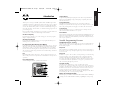 3
3
-
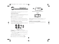 4
4
-
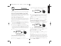 5
5
-
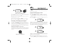 6
6
-
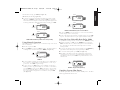 7
7
-
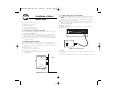 8
8
-
 9
9
-
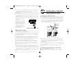 10
10
-
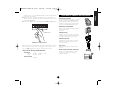 11
11
-
 12
12
-
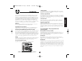 13
13
-
 14
14
-
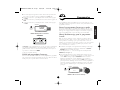 15
15
-
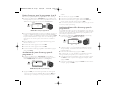 16
16
-
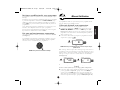 17
17
-
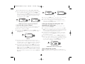 18
18
-
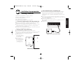 19
19
-
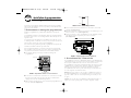 20
20
-
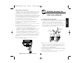 21
21
-
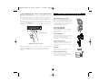 22
22
-
 23
23
-
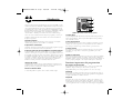 24
24
-
 25
25
-
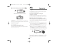 26
26
-
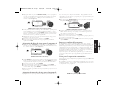 27
27
-
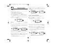 28
28
-
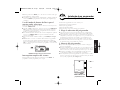 29
29
-
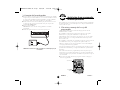 30
30
-
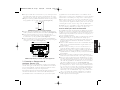 31
31
-
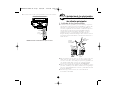 32
32
-
 33
33
-
 34
34
-
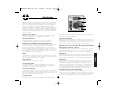 35
35
-
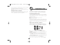 36
36
-
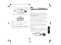 37
37
-
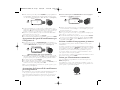 38
38
-
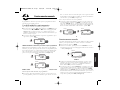 39
39
-
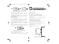 40
40
-
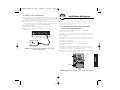 41
41
-
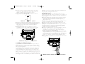 42
42
-
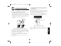 43
43
-
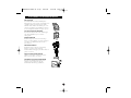 44
44
-
 45
45
-
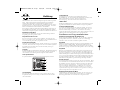 46
46
-
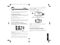 47
47
-
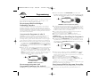 48
48
-
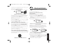 49
49
-
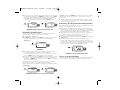 50
50
-
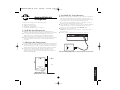 51
51
-
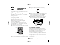 52
52
-
 53
53
-
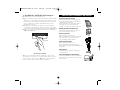 54
54
-
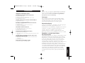 55
55
-
 56
56


Orbit WaterMaster 57692 Installation Manual & Users Manual
- Taper
- Installation Manual & Users Manual
dans d''autres langues
- italiano: Orbit WaterMaster 57692
- English: Orbit WaterMaster 57692
- español: Orbit WaterMaster 57692
- Deutsch: Orbit WaterMaster 57692
Documents connexes
-
Orbit WaterMaster 57196 Manuel utilisateur
-
Orbit 96880 Manuel utilisateur
-
-
-
Orbit 57874 Manuel utilisateur
-
-
Orbit 57899 Manuel utilisateur
-
-
-
Autres documents
-
 ORBIT IRRIGATION 57860 Le manuel du propriétaire
-
claber Tempo Select Mode d'emploi
-
Hozelock Sensor Plus Mode d'emploi
-
Rain Bird 32ETI Manuel utilisateur
-
Parkside 282463 Operation and Safety Notes
-
-
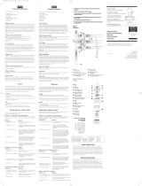 ORBIT IRRIGATION 57477 Le manuel du propriétaire
-
Hunter X2 Mode d'emploi
-
-
Chapin 41003 Manuel utilisateur

