

MM-014716-001, Rev. P
2
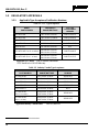
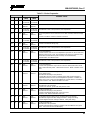
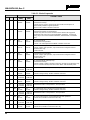
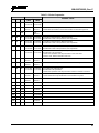
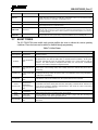
MANUAL REVISION HISTORY
REV
DATE
REASON FOR CHANGE
C Sep/09 Added VHF antennas, added “Enable/Disable Volume Side Tone,” and updated to Harris format.
D Apr/10
Added keypad lock/unlock instructions for ECP
, added REGISTER and BND SCAN to P25T
status messages.
E Jan/11 Updated antenna information; other minor updates.
F Apr/11 Updated for OTP R17, consolidated EDACS, Conventional, P25 operation into one section.
G Aug/11 Updated antennas; removed reference to ambient light sensor, minor edits.
H Oct/11 Added Part 80 information.
J Jan/12 Updated antennas and updated warranty.
K Oct/12 Added VHF antennas. Added stealth mode, PIN entry, and Control and Status Services.
L Jun/13 Added Audio Playback. Updated OpenSky operation.
M Mar/14 Added support for XG-75M. Added Sections 7.37 and 7.38. Updated Data TX/RX Indications.
N Oct/14 Updated for XGP R4A – added Voice Annunciation and APPENDIX A.
P Apr/15
Updated for XGP R5A.
Added Preset Buttons to EDACS, Conventional, and P25 operation
section. Added French Safety section.
ACKNOWLEDGEMENT
This device is made under license under one or more of the following US patents: 4,590,473; 4,636,791; 5,148,482; 5,185,796; 5,271,017;
5,377,229; 4,716,407; 4,972,460; 5,502,767; 5,146,497; 5,164,986; 5,185,795; 5,226,084; 5,247,579; ; 5,491,772; 5,517,511; 5,630,011;
5,649,050; 5,701,390; 5,715,365; 5,754,974; 5,826,222; 5,870,405; 6,161,089; and 6,199,037 B1. DVSI claims certain rights, including
patent rights under aforementioned U.S. patents, and under other U.S. and foreign patents and patents pending. Any use of this software or
technology requires a separate written license from DVSI.
CREDITS
EDACS, OpenSky, Harris, and VIDA are registered trademarks and TECHNOLOGY TO CONNECT, INFORM AND PROTECT is a
trademark of Harris Corporation.
AMBE is a registered trademark and IMBE, AMBE+, and AMBE+2 are trademarks of Digital Voice Systems, Inc.
All other brand and product names are trademarks, registered trademarks, or service marks of their respective holders.
NOTICE!
The material contained herein is subject to U.S. export approval. No export or re-export is permitted without written approval from the U.S.
Government. Rated: EAR99 in accordance with U.S. Dept. of Commerce regulations 15CFR774, Export Administration Regulations.
Information and descriptions contained herein are the property of Harris Corporation. Such information and descriptions may not be copied
or reproduced by any means, or disseminated or distributed without the express prior written permission of Harris Corporation, PSPC
Division, 221 Jefferson Ridge Parkway, Lynchburg, VA 24501.
Repairs to this equipment should be made only by an authorized service technician or facility designated by the supplier. Any repairs,
alterations or substitutions of recommended parts made by the user to this equipment not approved by the manufacturer could void the
user's authority to operate the equipment in addition to the manufacturer's warranty.
This product conforms to the European Union WEEE Directive 2012/19/EU. Do not dispose of this product in a public
landfill. Take it to a recycling center at the end of its life.
Harris products comply with the Restriction of the Use of Certain Hazardous Substances in Electrical and Electronic
Equipment (RoHS) Directive.
This manual is published by Harris Corporation without any warranty. Improvements and changes to this manual necessitated by
typographical errors, inaccuracies of current information, or improvements to programs and/or equipment, may be made by Harris
Corporation
at any time and without notice. Such c
hanges will be incorporated into new editions of this manual. No part of this manual
may be reproduced or transmitted in any form or by any means, electronic or mechanical, including photocopying and recording,
for any
purpose, without the express written
permission of Harris Corporation.
Copyright © 2008-2015 Harris Corporation.

MM-014716-001, Rev. P
3
TABLE OF CONTENTS
Page
1. REGULATORY AND SAFETY INFORMATION ............................................................................. 9
1.1 SAFETY SYMBOL CONVENTIONS ......................................................................................... 9
1.2 REGULATORY APPROVALS ................................................................................................. 10
1.2.1 Applicable Type Acceptance/Certification Numbers .................................................... 10
1.3 RADIO FREQUENCY INTERFERENCE ................................................................................. 11
1.3.1 FCC Part 15 ................................................................................................................... 11
1.3.2 Industry Canada ............................................................................................................. 11
1.4 RF ENERGY EXPOSURE AWARENESS AND CONTROL INFORMATION FOR FCC
OCCUPATIONAL USE REQUIREMENTS ............................................................................. 11
1.4.1 Federal Communications Commission Regulations ...................................................... 12
1.5 COMPLIANCE WITH RF EXPOSURE STANDARDS ........................................................... 12
1.5.1 Mobile Antennas ............................................................................................................ 13
1.5.2 Approved Accessories ................................................................................................... 13
1.5.3 Mobile Antennas (Vehicle Installations) ....................................................................... 14
1.5.4 Mobile Antennas (Motorcycle Installations) ................................................................. 17
1.6 OCCUPATIONAL SAFETY GUIDELINES AND SAFETY TRAINING INFORMATION .. 18
1.7 COMMON HAZARDS .............................................................................................................. 18
1.8 SAFE DRIVING RECOMMENDATIONS ................................................................................ 19
1.9 OPERATING RULES AND REGULATIONS .......................................................................... 20
1.10 OPERATING TIPS ..................................................................................................................... 20
2. RENSEIGNEMENTS SUR LA RÉGLEMENTATION ET SÉCURITÉ ....................................... 22
2.1 CONVENTIONS SUR LES SYMBOLES DE SÉCURITÉ ....................................................... 22
2.2 CONFORMITÉ À LA RÉGLEMENTATION ........................................................................... 23
2.2.1 Type Applicable Numéros Acceptation / Certification ................................................. 23
2.3 INTERFÉRENCE DES RADIOFRÉQUENCES ....................................................................... 23
2.3.1 Partie 15 de la FCC ........................................................................................................ 23
2.3.2 Industrie Canada ............................................................................................................ 23
2.4 RENSEIGNEMENTS SUR UNE EXPOSITION À L’ÉNERGIE DES RF ............................... 24
2.4.1 Renseignements Sur Le Contrôle Et La Sensibilisation À L’énergie Des RF Pour Les
Exigences D’une Utilisation Professionnelle De La FCC ............................................. 24
2.5 CONFORMITÉ AUX NORMES D’EXPOSITION AUX RF ................................................... 25
2.5.1 Antennes mobiles .......................................................................................................... 26
2.5.2 Accessoires approuvés ................................................................................................... 26
2.5.3 Monté Antennes (véhicule) ............................................................................................ 27
2.5.4 Monté Antennes (Motocyclette) .................................................................................... 32
2.6 RENSEIGNEMENTS SUR LA FORMATION SUR LA SANTÉ ET LA SÉCURITÉ AU
TRAVAIL ................................................................................................................................... 33
2.7 DANGERS COURANTS ........................................................................................................... 33
2.8 RECOMMANDATIONS POUR UNE CONDUITE SÉCURITAIRE ....................................... 34
2.9 RÈGLES ET RÉGLEMENTATIONS D'UTILISATION
.......................................................... 35
3. MARINE FREQUENCIES .................................................................................................................. 36
4. PRODUCT DESCRIPTION ................................................................................................................ 42
5. CHANGE OPERATING MODE (700/800 MHZ RADIOS ONLY) ................................................ 43
5.1 CHANGE FROM OTP MODE................................................................................................... 43
5.2 CHANGE TO OTP MODE......................................................................................................... 43

MM-014716-001, Rev. P
4
TABLE OF CONTENTS
Page
6. OPENSKY OPERATION (700/800 MHZ RADIOS ONLY) ............................................................ 44
6.1 CH-721 FRONT PANEL COMPONENTS ................................................................................ 44
6.2 POWER UP AND VOLUME CONTROL ................................................................................. 46
6.2.1 Power Up ....................................................................................................................... 46
6.2.2 Volume Control ............................................................................................................. 46
6.3 SELF-TEST ................................................................................................................................. 46
6.4 LOGIN TO THE NETWORK .................................................................................................... 46
6.5 LOG OFF THE NETWORK ....................................................................................................... 47
6.6 TURN THE RADIO OFF ........................................................................................................... 47
6.7 MENU DISPLAY AND CONTROL AREA .............................................................................. 47
6.8 RADIO STATUS ICONS ........................................................................................................... 48
6.9 DWELL DISPLAY ..................................................................................................................... 48
6.10 ERROR MESSAGES .................................................................................................................. 48
6.11 PERSONALITY.......................................................................................................................... 50
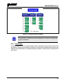
6.11.1 Profiles ........................................................................................................................... 50
6.11.2 Talk Groups ................................................................................................................... 51
6.12 ALERT TONES .......................................................................................................................... 52
6.13 BASIC MENU STRUCTURE .................................................................................................... 53
6.14 DUAL-TONE MULTI-FREQUENCY ....................................................................................... 55
6.15 KEYPAD ..................................................................................................................................... 56
6.15.1 Keypad Commands (System Model Control Head) ...................................................... 56
6.15.2 Quick Buttons (System Model Only) ............................................................................ 57
6.15.3 Keypad Lock/Unlock ..................................................................................................... 57
6.15.4 Password Entry .............................................................................................................. 57
6.15.5 DTMF Overdial ............................................................................................................. 58
6.16 CHANGE THE ACTIVE PROFILE ........................................................................................... 58
6.17 ENABLE/DISABLE VOLUME SIDE TONE ............................................................................ 58
6.18 CHECK OR CHANGE THE SELECTED TALK GROUP ....................................................... 58
6.19 ADJUST DISPLAY AND BUTTON BACKLIGHT BRIGHTNESS ........................................ 58
6.20 STEALTH MODE ...................................................................................................................... 59
6.20.1 Enable Stealth Mode ...................................................................................................... 59
6.20.2 Disable Stealth Mode ..................................................................................................... 59
6.21 ADJUST SIDE TONE AUDIO LEVEL ..................................................................................... 59
6.22 CHANGE OPERATING MODE ................................................................................................ 60
6.23 RECEIVE AND TRANSMIT VOICE CALLS .......................................................................... 60
6.23.1 Receive a Voice Call ................................................................
..................................... 60
6.23.2 Transmit a Voice Call .................................................................................................... 61
6.24 ADJUST AUDIO TREBLE LEVEL .......................................................................................... 61
6.25 INTERCOM MODE ................................................................................................................... 61
6.26 TALK GROUP LOCK OUT ....................................................................................................... 62
6.26.1 Lock Out a Talk Group .................................................................................................. 62
6.26.2 Unlock a Talk Group ..................................................................................................... 63
6.27 SCANNING ................................................................................................................................ 63
6.27.1 Check or Change Active Scan Mode ............................................................................. 64
6.27.2 Scan Priority .................................................................................................................. 64
6.27.3 Change Priority 1 and Priority 2 Talk Groups ............................................................... 64
6.27.4 Change Priority 3 Talk Groups ...................................................................................... 64

MM-014716-001, Rev. P
5
TABLE OF CONTENTS
Page
6.28 MAKE SELECTIVE CALLS ..................................................................................................... 65
6.28.1 Manually Dial a Selective Call (System Model Control Head) ..................................... 65
6.28.2 Speed Dial a Selective Call............................................................................................ 66
6.28.3 Receive a Selective Call ................................................................................................ 66
6.28.4 Terminate a Selective Call ............................................................................................. 66
6.29 SELECTIVE ALERT .................................................................................................................. 66
6.29.1 Send Selective Alert Messages ...................................................................................... 67
6.29.2 Receive Messages .......................................................................................................... 68
6.29.3 Define Pre-Programmed Messages ................................................................................ 68
6.30 TELEPHONE INTERCONNECT CALLS (SYSTEM MODEL CONTROL HEAD) .............. 68
6.30.1 Place an Interconnect Call ............................................................................................. 68
6.30.2 Receive an Interconnect Call ......................................................................................... 69
6.31 EMERGENCY COMMUNICATIONS ...................................................................................... 69
6.31.1 Declare an Emergency Call or Alert .............................................................................. 69
6.31.2 Silent Emergency ........................................................................................................... 70
6.31.3 Clear an Emergency Call or Alert ................................................................................. 70
6.31.4 Receive an Emergency Call ........................................................................................... 70
6.31.5 Dismiss an Emergency Call ........................................................................................... 71
6.32 ENCRYPTION ........................................................................................................................... 71
6.32.1 Automatic Encryption .................................................................................................... 71
6.32.2 Manual Encryption (System Model) ............................................................................. 72
6.33 PRESET BUTTONS ................................................................................................................... 73
6.34 STATUS MESSAGES ................................................................................................................ 73
6.34.1 Send Status Message via the Keypad (System Model Only) ......................................... 73
6.34.2 Send Status Message via the Menu ............................................................................... 74
6.35 REQUEST TO TALK (RTT) MESSAGES ................................................................................ 74
6.35.1 Send RTT Message via the Keypad (System Model Radios Only) ............................... 74
6.35.2 Send RTT Message via the Menu .................................................................................. 74
6.35.3 Send RTT Automatic Normal Message via the Quick Button ...................................... 74
6.35.4 Send RTT Automatic Priority Message via the Quick Button ...................................... 74
6.36 GPS COORDINATES ................................................................................................................ 75
6.37 SCENE-OF-INCIDENT MODE ................................................................................................. 75
7. EDACS/CONVENTIONAL/P25 (ECP/XGP) OPERATION ........................................................... 77
7.1 TURN THE RADIO ON ............................................................................................................. 77
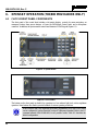
7.2 CH-721 FRONT PANEL COMPONENTS ................................................................................ 77
7.3 KEYPAD LOCK/UNLOCK ....................................................................................................... 79
7.4 PRESET BUTTONS ................................................................................................................... 79
7.5 RADIO STATUS ICONS ........................................................................................................... 80
7.6 MESSAGES ................................................................................................................................
81
7.7 ALERT TONES .......................................................................................................................... 83
7.8 MENU ......................................................................................................................................... 84
7.9 FEATURE ENCRYPTION DISPLAY ....................................................................................... 85
7.9.1 Serial Number ROM (12 Hex Digits) ............................................................................ 86
7.9.2 Feature Encryption Data Stream .................................................................................... 86
7.9.3 Features Enabled ............................................................................................................ 87
7.10 VOICE ANNUNCIATION ......................................................................................................... 88
7.11 SYSTEM/GROUP/CHANNEL SELECTION............................................................................ 88

MM-014716-001, Rev. P
6
TABLE OF CONTENTS
Page
7.11.1 System Selection ............................................................................................................ 88
7.11.2 Group and Channel Selection ........................................................................................ 89
7.12 LAST SYSTEM/GROUP/CHANNEL RECALL ....................................................................... 89
7.13 ENCRYPTION ........................................................................................................................... 89
7.13.1 Displaying the Currently Used Cryptographic Key Number ......................................... 89
7.13.2 Key Zero ........................................................................................................................ 90
7.13.3 Receive an Encrypted Call ............................................................................................. 90
7.13.4 Transmit an Encrypted Call ........................................................................................... 90
7.13.5 Emergencies on Encrypted Group ................................................................................. 90
7.14 MACRO KEY OPERATION ..................................................................................................... 91
7.15 RECEIVE A CALL ..................................................................................................................... 91
7.16 TRANSMIT A CALL ................................................................................................................. 91
7.17 CONVENTIONAL FAILSOFT (EDACS) ................................................................................. 91
7.18 EMERGENCY OPERATION .................................................................................................... 92
7.18.1 Receive an Emergency Call ........................................................................................... 92
7.18.2 Declare an Emergency ................................................................................................... 92
7.19 MIXED SYSTEM ZONES ......................................................................................................... 93
7.20 CALLER ID ................................................................................................................................ 93
7.21 STEALTH MODE ...................................................................................................................... 93
7.22 SYSTEM SCAN OPERATION (EDACS AND P25 TRUNKED) ............................................ 94
7.22.1 Wide Area System Scan (WA Scan) ............................................................................. 94
7.22.2 ProScan™ ...................................................................................................................... 94
7.22.3 Priority System Scan...................................................................................................... 94
7.22.4 When Wide Area System Scan is Enabled .................................................................... 94
7.22.5 When ProScan Is Enabled ............................................................................................. 94
7.22.6 Menu Selection .............................................................................................................. 95
7.22.7 Pre-Programmed Keypad Key ....................................................................................... 95
7.23 SCAN OPERATION ................................................................................................................... 95
7.23.1 Add Groups or Channels to a Scan List ......................................................................... 95
7.23.2 Delete Groups or Channels from a Scan List ................................................................ 96
7.23.3 Nuisance Delete ............................................................................................................. 96
7.23.4 Turn Scan On ................................................................................................................. 96
7.23.5 Priority Group/Channel Scanning .................................................................................. 97
7.23.6 Turn Scan Off ................................................................................................................ 97
7.23.7 Mixed Zone Scan ........................................................................................................... 97
7.24 INDIVIDUAL CALLS (EDACS AND P25 MODES) ............................................................... 98
7.24.1 Receive and Respond to an Individual Call ................................................................... 98
7.24.2 Call Storage Lists ........................................................................................................... 99
7.24.3 Send an Individual Call ................................
............................................................... 100
7.25 SCAT™ OPERATION ............................................................................................................. 100
7.26 TELEPHONE INTERCONNECT CALLS (EDACS AND P25) ............................................. 100
7.26.1 Receive a Telephone Interconnect Call ....................................................................... 100
7.26.2 Send a Telephone Interconnect Call ............................................................................ 100
7.26.3 DTMF Overdial/Conventional Mode Telephone Interconnect .................................... 101
7.26.4 Programmable Entries ................................................................................................. 101
7.27 MOBILE DATA (EDACS AND P25 TRUNKED) .................................................................. 102
7.27.1 Displays ....................................................................................................................... 102
7.27.2 Data Off Operation ...................................................................................................... 102

MM-014716-001, Rev. P
7
TABLE OF CONTENTS
Page
7.27.3 Data On Operation ....................................................................................................... 102
7.27.4 Exiting Data Calls ........................................................................................................ 103
7.27.5 Scan Lockout Mode ..................................................................................................... 103
7.27.6 Data Lockout Mode ..................................................................................................... 103
7.28 STATUS/MESSAGE OPERATION (EDACS AND P25 TRUNKED) ................................... 104
7.28.1 Status Operation .......................................................................................................... 104
7.28.2 Message Operation ...................................................................................................... 104
7.29 EDACS CONVENTIONAL P1 SCAN .................................................................................... 105
7.30 DYNAMIC REGROUP OPERATION (EDACS) .................................................................... 105
7.31 PAGE (P25 TRUNKED ONLY) .............................................................................................. 105
7.32 SQUELCH ADJUST (CONVENTIONAL) ............................................................................. 105
7.32.1 Menu Selection ............................................................................................................ 106
7.32.2 Pre-Programmed Keypad Key ..................................................................................... 106
7.33 TYPE 99 DECODE (ANALOG CONVENTIONAL) .............................................................. 106
7.33.1 Menu Selection ............................................................................................................ 107
7.33.2 Pre-Programmed Keypad Key ..................................................................................... 107
7.34 TALK-AROUND (ANALOG CONVENTIONAL) ................................................................. 107
7.35 CONTROL AND STATUS SERVICE ..................................................................................... 107
7.36 AUDIO PLAYBACK ............................................................................................................... 108
7.37 RADIO TEXTLINK OPERATION .......................................................................................... 108
7.37.1 Send TextLink Messages ............................................................................................. 108
7.37.2 Receive TextLink Messages ........................................................................................ 108
7.37.3 Delete TextLink Messages .......................................................................................... 108
7.37.4 Display Current Time .................................................................................................. 109
7.38 VIEW GPS INFORMATION ................................................................................................... 109
8. BASIC TROUBLESHOOTING ........................................................................................................ 110
9. CUSTOMER SERVICE .................................................................................................................... 111
9.1 CUSTOMER CARE ................................................................................................................. 111
9.2 TECHNICAL ASSISTANCE ................................................................................................... 111
10. KEYPAD REMAPPING .................................................................................................................... 112
11. RADIO SETUP ................................................................................................................................... 113
12. WARRANTY ...................................................................................................................................... 116
APPENDIX A - CONFIGURING ENCRYPTION ................................................................................. 117
FIGURES
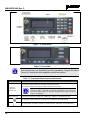
Figure 6-1: System Model ....................................................................................................................... 44
Figure 6-2: Scan Model ........................................................................................................................... 44
Figure 6-3: Typical Display ..................................................................................................................... 47
Figure 6-4: Personality Structure Example ............................................................................................. 51
Figure 7-1: System Model ....................................................................................................................... 78
Figure 7-2: Scan Model ........................................................................................................................... 78
Figure 7-3: Typical Display ..................................................................................................................... 80

MM-014716-001, Rev. P
8
TABLE OF CONTENTS
Page
TABLES
Table 1-1: FCC Type Acceptance .......................................................................................................... 10
Table 1-2: Industry Canada Type Acceptance........................................................................................ 10
Table 1-3: Rated Power and Recommended Minimum Safe Lateral Distance (Vehicle
Installations) .......................................................................................................................... 14
Table 1-4: Rated Power and Recommended Minimum Safe Lateral Distance (Motorcycle
Installation) ........................................................................................................................... 17
Tableau 2-1: FCC Type de Acceptation ................................................................................................. 23
Tableau 2-2: Type de Canada Industrie Acceptation ............................................................................. 23
Tableau 2-3 : Distance latérale sécuritaire minimale recommandée d’une antenne de
transmission branchée sur une radio mobile ......................................................................... 27
Tableau 2-4: Distance latérale sécuritaire minimale recommandée d’une antenne de
transmission branchée sur une radio Motocyclette ............................................................... 32
Table 3-1: Marine Frequencies ................................................................................................................ 36
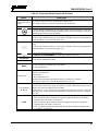
Table 6-1: Front Panel Default Controls and Functions .......................................................................... 45
Table 6-2: Icons and Descriptions ........................................................................................................... 48
Table 6-3: XG-75M/M7300 OpenSky Mode Alert Tones ...................................................................... 52
Table 6-4: Basic Menu Structure ............................................................................................................. 53
Table 6-5: Keypad Function Commands ................................................................................................. 56
Table 6-6: Quick Button Functions ......................................................................................................... 57
Table 6-7: Scan Modes ............................................................................................................................ 63
Table 6-8: Status of Selective Call .......................................................................................................... 65
Table 6-9: Status of Selective Alert ......................................................................................................... 67
Table 7-1: Front Panel Default Controls and Functions .......................................................................... 78
Table 7-2: Icons and Descriptions ........................................................................................................... 80
Table 7-3: Radio Messages ..................................................................................................................... 81
Table 7-4: Alert Tones ............................................................................................................................. 83
Table 7-5: Menu Item Information .......................................................................................................... 84
Table 7-6: Available Feature Numbers ................................................................................................... 87
Table 7-7: Current Cryptographic Key Display ...................................................................................... 90
Table 8-1: Basic Troubleshooting ......................................................................................................... 110
Harris Corporation, Public Safety and Professional Communications (PSPC) Business, continually evaluates its technical
publications for completeness, technical accuracy, and organization. You can assist in this process by submitting your
comments and suggestions to the following:
Harris Corporation fax your comments to: 1-434-455-6851
PSPC Business or
Technical Publications e-mail us at: PSPC
_
TechPubs
@
harris.com
221 Jefferson Ridge Parkway
Lynchburg, VA 24501

MM-014716-001, Rev. P
9
1. REGULATORY AND SAFETY INFORMATION
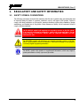
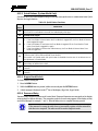
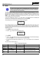
1.1 SAFETY SYMBOL CONVENTIONS
The following conventions are used in this manual to alert the user to general safety precautions that must
be observed during all phases of operation, installation, service, and repair of this product. Failure to
comply with these precautions or with specific warnings elsewhere violates safety standards of design,
manufacture, and intended use of the product. Harris assumes no liability for the customer's failure to
comply with these standards.
The WARNING symbol calls attention to a procedure, practice, or the like, which,
if not correctly performed or adhered to, could result in personal injury. Do not
proceed beyond a WARNING symbol until the conditions identified are fully
understood or met.
The CAUTION symbol calls attention to an operating procedure, practice, or the like,
which, if not performed correctly or adhered to, could result in damage to the equipment
or severely degrade equipment performance.
The NOTE symbol calls attention to supplemental information, which may improve
system performance or clarify a process or procedure.
NOTE

MM-014716-001, Rev. P
10
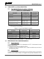
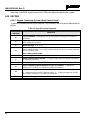
1.2 REGULATORY APPROVALS
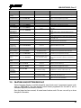
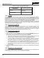
1.2.1 Applicable Type Acceptance/Certification Numbers
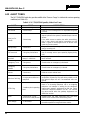
Table 1-1: FCC Type Acceptance
RADIO
PART NUMBER
FREQUENCY
RANGE/WATTAGE
FCC TYPE
ACCEPTANCE
NUMBER
RU-144750-041 136-174 MHz, 50 Watt OWDTR-0055-E
RU-144750-051 136-174 MHz, 110 Watt OWDTR-0056-E
RU-144750-021 378-430 MHz, 50 Watt OWDTR-0061-E
RU-144750-031 440-512 MHz, 50 Watt OWDTR-0062-E
14018-0010-01 330-380 MHz, 40 Watt N/A
1
RU-144750-061 Rev. K or earlier)
764-806 MHz, 30 Watt
806-870 MHz, 35 Watt
OWDTR-0060-E
RU-144750-061 (Rev. L or later)
764-806 MHz, 30 Watt
806-870 MHz, 35 Watt
OWDTR-0132-E
Applicable FCC Rules: Part 15, Part 80*, and Part 90
* FCC Part 80 is for 156-162 MHz only.
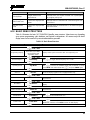
Table 1-2: Industry Canada Type Acceptance
RADIO
PART NUMBER
FREQUENCY
RANGE/WATTAGE
IC TYPE ACCEPTANCE
NUMBER
RU-144750-041 136-174 MHz, 50 Watt 3636B-0055
RU-144750-051 136-174 MHz, 110 Watt 3636B-0056
RU-144750-021 378-430 MHz, 50 Watt 3636B-0061
RU-144750-031 440-512 MHz, 50 Watt 3636B-0062
14018-0010-01
330-380 MHz, 40 Watt
N/A
1
RU-144750-061
(Rev. K or earlier)
764-806 MHz, 30 Watt
806-870 MHz, 35 Watt
3636B-0051
RU-144750-061
(Rev. L or later)
764-806 MHz, 30 Watt
806-870 MHz, 35 Watt
3636B-0132
Applicable Industry Canada Rules: RSS 119; RSS 210
1
The 14018-0010-01 model is not sold or used in North America.

MM-014716-001, Rev. P
11
1.3 RADIO FREQUENCY INTERFERENCE
1.3.1 FCC Part 15
This device complies with Part 15 of the FCC Rules. Operation is subject to the following two conditions:
1. This device may not cause harmful interference; and,
2. This device must accept any interference received, including interference that may cause undesired operation.
1.3.2 Industry Canada
This device complies with Industry Canada license-exempt RSS standard(s). Operation is subject to the
following two conditions: (1) this device may not cause interference, and (2) this device must accept any
interference, including interference that may cause undesired operation of the device.
Le présent appareil est conforme aux CNR d'Industrie Canada applicables aux appareils radio exempts de
licence. L'exploitation est autorisée aux deux conditions suivantes : (1) l'appareil ne doit pas produire de
brouillage, et (2) l'utilisateur de l'appareil doit accepter tout brouillage radioélectrique subi, même si le
brouillage est susceptible d'en compromettre le fonctionnement.
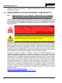
1.4 RF ENERGY EXPOSURE AWARENESS AND CONTROL
INFORMATION FOR FCC OCCUPATIONAL USE REQUIREMENTS
Before using the two-way mobile radio, review the following important RF energy awareness and
control information and operational instructions. Comply with this information and instructions to
ensure compliance with RF exposure guidelines.
This radio is intended for use in occupational/controlled conditions, where users
have full knowledge of their exposure and can exercise control over their exposure
to remain below RF exposure limits. This radio is NOT authorized for general
population, consumer, or any other use.
Changes or modifications not expressly approved by Harris could void the user's
authority to operate the equipment.
This two-way radio uses electromagnetic energy in the radio frequency (RF) spectrum to provide
communications between two or more users over a distance. It uses RF energy or radio waves to send and
receive calls. RF energy is one form of electromagnetic energy. Other forms include, but are not limited
to, electric power, sunlight, and x-rays. RF energy, however, should not be confused with these other
forms of electromagnetic energy, which, when used improperly, can cause biological damage. Very high
levels of x-rays, for example, can damage tissues and genetic material.
Experts in science, engineering, medicine, health, and industry work with organizations to develop
standards for exposure to RF energy. These standards provide recommended levels of RF exposure for
both workers and the general public. These recommended RF exposure levels include substantial margins

MM-014716-001, Rev. P
12
of protection. All two-way radios marketed in North America are designed, manufactured, and tested to
ensure they meet government-established RF exposure levels. In addition, manufacturers also recommend
specific operating instructions to users of two-way radios. These instructions are important because they
inform users about RF energy exposure and provide simple procedures on how to control it. Refer to the
following websites for more information on what RF energy exposure is and how to control exposure to
assure compliance with established RF exposure limits:
http://www.fcc.gov/oet/rfsafety/rf-faqs.html
http://www.osha.gov./SLTC/radiofrequencyradiation/index.html
1.4.1 Federal Communications Commission Regulations
Before it was marketed in the United States, the XG-75M/M7300 series two-way mobile radios were
tested to ensure compliance with FCC RF energy exposure limits for two-way mobile radios. When two-
way radios are used as a consequence of employment, the FCC requires users to be fully aware of and
able to control their exposure to meet occupational requirements. Exposure awareness can be facilitated
by the use of a label directing users to specific user awareness information. The radio has an RF exposure
product label. Also, this Product Safety Manual and the applicable Operator’s Manual include
information and operating instructions required to control RF exposure and to satisfy compliance
requirements.
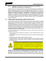
1.5 COMPLIANCE WITH RF EXPOSURE STANDARDS
The XG-75M/M7300 series two-way mobile radios are designed and tested to comply with a number of
national and international standards and guidelines regarding human exposure to RF electromagnetic
energy. The radios comply with the IEEE and ICNIRP exposure limits for occupational/controlled RF
exposure environment at duty-cycle times of up to 50% (50% transmit, 50% receive) and it is authorized
by the FCC for occupational use. In terms of measuring RF energy for compliance with the FCC exposure
guidelines, each radio’s antenna radiates measurable RF energy only while it is transmitting (talking), not
when it is receiving (listening), or in a standby mode.
The XG-75M/M7300 series two-way mobile radios comply with the following RF energy exposure
standards and guidelines:
• United States Federal Communications Commission (FCC), Code of Federal Regulations; 47
CFR § 2 sub-part J.
• American National Standards Institute (ANSI)/Institute of Electrical and Electronic Engineers (IEEE)
C95.1-2005.
• Institute of Electrical and Electronic Engineers (IEEE) C95.1-2005.
• IC Standard RSS-102, Issue 4, 2010: Spectrum Management and Telecommunications Radio
Standards Specification. Radiofrequency Exposure Compliance of Radiocommunication Apparatus
(All Frequency Bands).
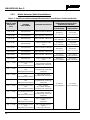
Table 1-3 and Table 1-4 list the recommended minimum safe lateral distances for a
controlled environment and for unaware bystanders in an uncontrolled environment,
from transmitting antennas (i.e., monopoles over a ground plane, or dipoles) at rated
radio power for mobile radios installed in a vehicle. Transmit only when unaware
bystanders are at least the uncontrolled recommended minimum safe lateral distance
away from the transmitting antenna.

MM-014716-001, Rev. P
13
Based on the highest radiated RF power and the highest antenna gain in antennas used with XG-
75M/M7300 series radios, the distances listed in Table 1-3 and Table 1-4 are considered as safe distances
for controlled and uncontrolled environments with the XG-75M/M7300 series mobile radios transmitting
at a maximum 50% duty cycle:
1.5.1 Mobile Antennas
The antenna(s) for the radio must be installed in accordance with the antenna installation procedures
presented in the radio’s Installation Manual. Also refer to any special instructions included with the
antenna.
Use only approved/supplied antenna(s) or an approved replacement antenna. Unauthorized antennas,
modifications, or attachments can cause the FCC RF exposure limits to be exceeded.
1.5.2 Approved Accessories
The radio has been tested and meets FCC RF guidelines when used with accessories supplied or
designated for use with it. Use of other accessories may not ensure compliance with the FCC’s RF
exposure guidelines, and may violate FCC regulations. For a list of approved accessories, refer to the
radio’s Installation Manual and/or to the Products and Services Catalog.

MM-014716-001, Rev. P
14
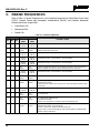
1.5.3 Mobile Antennas (Vehicle Installations)
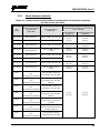
Table 1-3: Rated Power and Recommended Minimum Safe Lateral Distance (Vehicle Installations)
MOBILE RADIO
FREQUENCY
SPLIT
ANTENNA
PART NUMBER
ANTENNA DESCRIPTION
RECOMMENDED MINIMUM LATERAL
HUMAN BODY DISTANCE FROM
TRANSMITTING ANTENNA
CONTROLLED
ENVIRONMENT
UNCONTROLLED
ENVIRONMENT
VHF (50 W) AN-225002-001 136 to 174 MHz, 0 dBd Gain
24.8 Inches
(63 Centimeters)
55.1 Inches
(140 Centimeters)
VHF (50 W) AN-225006-001 132 to 960 MHz, 0 dBd Gain*
VHF (50 W)
AN-225002-003 136 to 174 MHz, 3 dBd Gain*
35.0 Inches
(89 Centimeters)
78.0 Inches
(198 Centimeters)
VHF (50 W)
AN-225002-004
136 to 174 MHz, 2.4 dBd
Gain*
32.7 Inches
(83 Centimeters)
72.8 Inches
(185 Centimeters)
VHF (110 W) AN-225002-001 136 to 174 MHz, 0 dBd Gain
36.6 Inches
(93 Centimeters)
81.9 Inches
(208 Centimeters)
VHF (110 W) AN-225006-001 132 to 960 MHz, 0 dBd Gain*
VHF (110 W)
AN-225002-003 136 to 174 MHz, 3 dBd Gain*
52.0 Inches
(132 Centimeters)
115.7 Inches
(294 Centimeters)
VHF (110 W)
AN-225002-004
136 to 174 MHz, 2.4 dBd
Gain*
48.4 Inches
(123 Centimeters)
107.9 Inches
(274 Centimeters)
UHF – L (50 W)
AN-125001-001 (mount)
with
AN-225003-001 (element)
378 to 430 MHz Standard
Rooftop-Mount; 0 dBd Gain
21.3 Inches
(54 Centimeters)
47.2 Inches
(120 Centimeters)
UHF – L (50 W)
AN-125001-001 (mount)
with
AN-225003-004 (element)
378 to 430 MHz Standard
Rooftop-Mount; Low-Profile
0 dBd Gain
UHF – L (50 W)
AN-125001-003 (mount)
with
AN-225003-001 (element)
378 to 430 MHz Thick
Rooftop-Mount; 0 dBd Gain
UHF – L (50 W)
AN-125001-003 (mount)
with
AN-225003-004 (element)
378 to 430 MHz Thick
Rooftop-Mount; Low-Profile
0 dBd Gain
UHF – L (50 W)
AN-125001-005 (mount)
with
AN-225003-001 (element)
378 to 430 MHz
GPS Combo, Standard
Rooftop-Mount; 0 dBd Gain
UHF – L (50 W)
AN-125001-005 (mount)
with
AN-225003-004 (element)
378 to 430 MHz
GPS Combo, Standard
Rooftop-Mount; Low-Profile
0 dBd Gain
UHF – L (50 W)
AN-125001-007 (mount)
with
AN-225003-001 (element)
378 to 430 MHz Magnetic-
Mount;
0 dBd Gain
UHF – L (50 W)
AN-125001-007 (mount)
with
AN-225003-004 (element)
378 to 430 MHz Magnetic-
Mount;
Low-Profile 0 dBd Gain

MM-014716-001, Rev. P
15
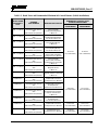
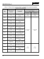
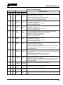
Table 1-3: Rated Power and Recommended Minimum Safe Lateral Distance (Vehicle Installations)
MOBILE RADIO
FREQUENCY
SPLIT
ANTENNA
PART NUMBER
ANTENNA DESCRIPTION
RECOMMENDED MINIMUM LATERAL
HUMAN BODY DISTANCE FROM
TRANSMITTING ANTENNA
CONTROLLED
ENVIRONMENT
UNCONTROLLED
ENVIRONMENT
UHF – H (50 W)
AN-125001-001 (mount)
with
AN-225004-001 (element)
450 to 512 MHz
Standard Rooftop-Mount;
0 dBd Gain
20 Inches
(51 Centimeters)
45 Inches
(114 Centimeters)
UHF – H (50 W)
AN-125001-001 (mount)
with
AN-225004-004 (element)
450 to 512 MHz
Standard Rooftop-Mount;
Low-Profile 0 dBd Gain
UHF – H (50 W)
AN-125001-003 (mount)
with
AN-225004-001 (element)
450 to 512 MHz
Thick Rooftop-Mount;
0 dBd Gain
UHF – H (50 W)
AN-125001-003 (mount)
with
AN-225004-004 (element)
450 to 512 MHz
Thick Rooftop-Mount;
Low-Profile 0 dBd Gain
UHF – H (50 W)
AN-125001-005 (mount)
with
AN-225004-001 (element)
450 to 512 MHz
GPS Combo, Standard
Rooftop-Mount; 0 dBd Gain
UHF – H (50 W)
AN-125001-005 (mount)
with
AN-225004-004 (element)
450 to 512 MHz
GPS Combo, Standard
Rooftop-Mount; Low-Profile
0 dBd Gain
UHF – H (50 W)
AN-125001-007 (mount)
with
AN-225004-001 (element)
450 to 512 MHz
Magnetic-Mount;
0 dBd Gain
UHF – H (50 W)
AN-125001-007 (mount)
with
AN-225004-004 (element)
450 to 512 MHz
Magnetic-Mount; Low-Profile
0 dBd Gain
700/800 MHz
AN-125001-002 (mount)
with
AN-225001-001 (element)
700/800 MHz Standard
Rooftop-Mount; 3 dBd Gain
9.8 Inches
(25 Centimeters)
21.7 Inches
(55 Centimeters)
700/800 MHz
AN-125001-002 (mount)
with
AN-225001-002 (element)
700/800 MHz Standard
Rooftop-Mount;
Elevated-Feed 3 dBd Gain
700/800 MHz
AN-125001-002 (mount)
with
AN-225001-003 (element)
700/800 MHz Standard
Rooftop-Mount; Elevated-
Feed, No Ground Plane
3 dBd Gain
700/800 MHz
AN-125001-002 (mount)
with
AN-225001-004 (element)
700/800 MHz Standard
Rooftop-Mount;
Low-Profile 2 dBd Gain
700/800 MHz
AN-125001-002 (mount)
with
AN-225001-005 (element)
700/800 MHz Standard
Rooftop-Mount; 5 dBd Gain
11.8 Inches
(30 Centimeters)
23.6 Inches
(60 Centimeters)
700/800 MHz
AN-125001-004 (mount)
with
AN-225001-001 (element)
700/800 MHz Thick
Rooftop-Mount; 3 dBd Gain
9.8 Inches
(25 Centimeters)
21.7 Inches
(55 Centimeters)

MM-014716-001, Rev. P
16
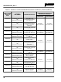
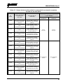
Table 1-3: Rated Power and Recommended Minimum Safe Lateral Distance (Vehicle Installations)
MOBILE RADIO
FREQUENCY
SPLIT
ANTENNA
PART NUMBER
ANTENNA DESCRIPTION
RECOMMENDED MINIMUM LATERAL
HUMAN BODY DISTANCE FROM
TRANSMITTING ANTENNA
CONTROLLED
ENVIRONMENT
UNCONTROLLED
ENVIRONMENT
700/800 MHz
AN-125001-004 (mount)
with
AN-225001-002 (element)
700/800 MHz Thick
Rooftop-Mount; Elevated-
Feed 3 dBd Gain
9.8 Inches
(25 Centimeters)
21.7 Inches
(55 Centimeters)
700/800 MHz
AN-125001-004 (mount)
with
AN-225001-003 (element)
700/800 MHz Thick
Rooftop-Mount; Elevated-
Feed, No Ground Plane
3 dBd Gain
700/800 MHz
AN-125001-004 (mount)
with
AN-225001-004 (element)
700/800 MHz Thick
Rooftop-Mount; Low-Profile
2 dBd Gain
700/800 MHz
AN-125001-004 (mount)
with
AN-225001-005 (element)
700/800 MHz Thick
Rooftop-Mount; 5 dBd Gain
11.8 Inches
(30 Centimeters)
23.6 Inches
(60 Centimeters)
700/800 MHz
AN-125001-006 (mount)
with
AN-225001-001 (element)
700/800 MHz GPS Combo
Rooftop-Mount; 3 dBd /
5.15 dBi Gain
9.8 Inches
(25 Centimeters)
21.7 Inches
(55 Centimeters)
700/800 MHz
AN-125001-006 (mount)
with
AN-225001-002 (element)
700/800 MHz GPS Combo
Rooftop-Mount;
Elevated-Feed 3 dBd Gain
700/800 MHz
AN-125001-006 (mount)
with
AN-225001-003 (element)
700/800 MHz GPS Combo
Rooftop-Mount; Elevated-
Feed, No Ground Plane
3 dBd Gain
700/800 MHz
AN-125001-006 (mount)
with
AN-225001-004 (element)
700/800 MHz GPS Combo
Rooftop-Mount; Low-Profile
2 dBd Gain
700/800 MHz
AN-125001-006 (mount)
with
AN-225001-005 (element)
700/800 MHz GPS Combo
Rooftop-Mount; 5 dBd /
7.15 dBi Gain
11.8 Inches
(30 Centimeters)
23.6 Inches
(60 Centimeters)
700/800 MHz
AN-125001-008 (mount)
with
AN-225001-001 (element)
700/800 MHz Magnetic-
Mount; 3 dBd Gain
9.8 Inches
(25 Centimeters)
21.7 Inches
(55 Centimeters)
700/800 MHz
AN-125001-008 (mount)
with
AN-225001-002 (element)
700/800 MHz Magnetic-
Mount;
Elevated-Feed 3 dBd Gain
700/800 MHz
AN-125001-008 (mount)
with
AN-225001-003 (element)
700/800 MHz Magnetic-
Mount; Elevated-Feed, No
Ground Plane 3 dBd Gain
700/800 MHz
AN-125001-008 (mount)
with
AN-225001-004 (element)
700/800 MHz Magnetic-
Mount;
Low-Profile 2 dBd Gain
700/800 MHz
AN-125001-008 (mount)
with
AN-225001-005 (element)
700/800 MHz Magnetic-
Mount; 5 dBd Gain
11.8 Inches
(30 Centimeters)
23.6 Inches
(60 Centimeters)

MM-014716-001, Rev. P
17
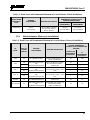
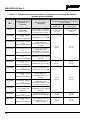
Table 1-3: Rated Power and Recommended Minimum Safe Lateral Distance (Vehicle Installations)
MOBILE RADIO
FREQUENCY
SPLIT
ANTENNA
PART NUMBER
ANTENNA DESCRIPTION
RECOMMENDED MINIMUM LATERAL
HUMAN BODY DISTANCE FROM
TRANSMITTING ANTENNA
CONTROLLED
ENVIRONMENT
UNCONTROLLED
ENVIRONMENT
700/800 MHz
STI-Co
CCAS-SB-700
760 - 820 MHz Concealed
Peal-and-Stick Internal-
Mount; dBi Gain
7.9 Inches
(20 Centimeters)
19.7 Inches
(50 Centimeters)
* Element must be trimmed to proper length to minimize antenna system VSWR.
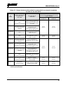
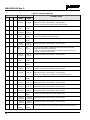
1.5.4 Mobile Antennas (Motorcycle Installations)
Table 1-4: Rated Power and Recommended Minimum Safe Lateral Distance (Motorcycle Installation)
RF
BAND
MAX. TX
POWER
(WATTS)
ANTENNA
PART NUMBER
ANTENNA DESCRIPTION
RECOMMENDED MINIMUM
LATERAL HUMAN BODY
DISTANCE FROM TRANSMITTING
ANTENNA
CONTROLLED
ENVIRONMENT
(Centimeters)
UNCONTROLLE
D
ENVIRONMENT
(Centimeters)
VHF 20 LE-OM150K.125/TNC
136 to 174 MHz Motorcycle-
Mount; 2.5 dBd Gain
53 118
VHF
18
AN-125001-005 (mount)
with
AN-225002-004 (element)
136 to 174 MHz GPS Combo;
No-Ground-Plane (NGP);
2.4 dBd Gain
50 —
3.6 — 50
UHF- L
43
AN-125001-005 (mount)
with
AN-225003-005 (element)
378 to 430 MHz GPS Combo,
No-Ground-Plane (NGP), 0 dBd
Gain
50 —
8.5 — 50
UHF - H
47
AN-125001-005 (mount)
with
AN-225004-005 (element)
450 to 512 MHz GPS Combo,
No-Ground-Plane (NGP), 0 dBd
Gain
50 —
9.5 — 50
800 MHz 20 LE-OM806HDBKTNCDS
800 MHz Motorcycle-Mount;
3.5 dBd Gain
28 72
700 or 800 MHz
20
AN-125001-006 (mount)
with
AN-225001-003 (element)
700/800 MHz GPS Combo; no-
Ground-Plane (NGP);
3 dBd / 5.15 dBi Gain
50 50

MM-014716-001, Rev. P
18
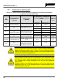
A radio used in a motorcycle installation must be configured with a transmit output
power level less than or equal to the MAX. TX POWER (WATTS) specification listed in
Table 1-4 for the respective frequency band and antenna/antenna element. Refer to the
radio’s Installation Manual for additional information.
When a later-
design motorcycle installation kit is employed (which uses antenna
element AN-225001-003 or AN-225002-004), the coaxial cable between the radio and
the base of the antenna mount cannot be shorter than 44 inches (111.8 centimeters).
Refer to the radio’s Installation Manual for additional information.
A radio intended for a non-motorcycle installation should not be used in a motorcycle
installation unless it is reprogrammed per the procedures presented in the radio’s
Installation Manual.
1.6 OCCUPATIONAL SAFETY GUIDELINES AND SAFETY TRAINING
INFORMATION
To ensure bodily exposure to RF electromagnetic energy is within the FCC allowable limits for
occupational use. Always adhere to the following basic guidelines:
• The push-to-talk button should only be depressed when intending to send a voice message.
• The radio should only be used for necessary work-related communications.
• The radio should only be used by authorized and trained personnel. It should never be operated by
children.
• Do not attempt any unauthorized modification to the radio. Changes or modifications to the radio may
cause harmful interference and/or cause it to exceed FCC RF exposure limits. Only qualified
personnel should service the radio.
• Always use only authorized accessories (antennas, control heads, speakers/mics, etc.). Use of
unauthorized accessories can cause the FCC RF exposure compliance requirements to be exceeded.
The information listed above provides the user with information needed to make him or her aware of a RF
exposure, and what to do to assure that this radio operates within the FCC exposure limits of this radio.
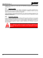
1.7 COMMON HAZARDS
The operator of any mobile radio should be aware of certain hazards common to
the operation of vehicular radio transmissions. Possible hazards include but are not
limited to:
• Explosive Atmospheres — Just as it is dangerous to fuel a vehicle while its engine is running, be
sure to turn the radio OFF while fueling the vehicle. If the radio is mounted in the trunk of the
vehicle, DO NOT carry containers of fuel in the trunk.
Areas with potentially explosive atmosphere are often, but not always, clearly marked. Turn the radio
OFF when in any area with a potentially explosive atmosphere. It is rare, but not impossible that the
radio or its accessories could generate sparks.

MM-014716-001, Rev. P
19
• Interference To Vehicular Electronic Systems — Electronic fuel injection systems, electronic anti-
skid braking systems, electronic cruise control systems, etc., are typical of the types of electronic
devices that can malfunction due to the lack of protection from radio frequency (RF) energy present
when transmitting. If the vehicle contains such equipment, consult the dealer for the make of vehicle
and enlist his aid in determining if such electronic circuits perform normally when the radio is
transmitting.
• Electric Blasting Caps — To prevent accidental detonation of electric blasting caps, DO NOT use
two-way radios within 1000 feet (305 meters) of blasting operations. Always obey the “Turn Off
Two-Way Radios” (or equivalent) signs posted where electric blasting caps are being used. (OSHA
Standard: 1926.900).
• Radio Frequency Energy — To prevent burns or related physical injury from radio frequency
energy, do not operate the transmitter when anyone outside of the vehicle is within the minimum safe
distance from the antenna as specified in Table 1-3 and Table 1-4. Refer to Section 1.2 for additional
information.
• Vehicles Powered By Liquefied Petroleum (LP) Gas — Radio installation in vehicles powered by
liquefied petroleum gas, where the LP gas container is located in the trunk or other sealed-off space
within the interior of the vehicle, must conform to the National Fire Protection Association standard
NFPA 58. This requires:
The space containing the radio equipment must be isolated by a seal from the space containing
the LP gas container and its fittings.
Outside filling connections must be used for the LP gas container.
The LP gas container space shall be vented to the outside of the vehicle.
• Vehicles Equipped with Airbags — For driver and passenger safety, avoid mounting the radio’s
control head (or any other component) above or near airbag deployment areas. In addition to driver-
side and passenger-side front-impact airbags, some vehicles may also be equipped with side-impact
airbags. For occupant safety, verify the location of all airbags within the vehicle before installing the
radio equipment.
1.8 SAFE DRIVING RECOMMENDATIONS
The American Automobile Association (AAA) advocates the following key safe driving recommenda-
tions:
• Read the literature on the safe operation of the radio.
• Keep both hands on the steering wheel and the microphone in its hanger whenever the vehicle is in
motion.
• Place calls only when the vehicle is stopped.
• When talking from a moving vehicle is unavoidable, drive in the slower lane. Keep conversations
brief.
• If a conversation requires taking notes or complex thought, stop the vehicle in a safe place and
continue the call.
• Whenever using a mobile radio, exercise caution.

MM-014716-001, Rev. P
20
1.9 OPERATING RULES AND REGULATIONS
Two-way radio systems must be operated in accordance with the rules and regulations of the local,
regional, or national government.
In the United States, the XG-75M/M7300 mobile radio must be operated in accordance with the rules and
regulations of the Federal Communications Commission (FCC). Operators of two-way radio equipment
must be thoroughly familiar with the rules that apply to the particular type of radio operation. Following
these rules helps eliminate confusion, assures the most efficient use of the existing radio channels, and
results in a smoothly functioning radio network.
Under U.S. law, operation of an unlicensed radio transmitter within the jurisdiction of
the United States may be punishable by a fine of up to $10,000, imprisonment for up to
two (2) years, or both.
When using a two-way radio, remember these rules:
• It is a violation of FCC rules to interrupt any distress or emergency message. The radio operates in
much the same way as a telephone “party line.” Therefore, always listen to make sure the channel is
clear before transmitting. Emergency calls have priority over all other messages. If someone is
sending an emergency message – such as reporting a fire or asking for help in an accident, do not
transmit unless assistance can be offered.
• The use of profane or obscene language is prohibited by Federal law.
• It is against the law to send false call letters or false distress or emergency messages. The FCC
requires keeping conversations brief and confined to business. Use coded messages whenever
possible to save time.
• Using the radio to send personal messages (except in an emergency) is a violation of FCC rules. Send
only essential messages.
• It is against Federal law to repeat or otherwise make known anything overheard on the radio.
Conversations between others sharing the channel must be regarded as confidential.
• The FCC requires self-identification at certain specific times by means of call letters. Refer to the
rules that apply to the particular type of operation for the proper procedure.
• No changes or adjustments shall be made to the equipment except by an authorized or certified
electronics technician.
1.10 OPERATING TIPS
The following conditions tend to reduce the effective range of two-way radios and should be avoided
whenever possible:
• Operating the radio in areas of low terrain, or while under power lines or bridges.
• Obstructions such as mountains and buildings.
La page est en cours de chargement...
La page est en cours de chargement...
La page est en cours de chargement...
La page est en cours de chargement...
La page est en cours de chargement...
La page est en cours de chargement...
La page est en cours de chargement...
La page est en cours de chargement...
La page est en cours de chargement...
La page est en cours de chargement...
La page est en cours de chargement...
La page est en cours de chargement...
La page est en cours de chargement...
La page est en cours de chargement...
La page est en cours de chargement...
La page est en cours de chargement...
La page est en cours de chargement...
La page est en cours de chargement...
La page est en cours de chargement...
La page est en cours de chargement...
La page est en cours de chargement...
La page est en cours de chargement...
La page est en cours de chargement...
La page est en cours de chargement...
La page est en cours de chargement...
La page est en cours de chargement...
La page est en cours de chargement...
La page est en cours de chargement...
La page est en cours de chargement...
La page est en cours de chargement...
La page est en cours de chargement...
La page est en cours de chargement...
La page est en cours de chargement...
La page est en cours de chargement...
La page est en cours de chargement...
La page est en cours de chargement...
La page est en cours de chargement...
La page est en cours de chargement...
La page est en cours de chargement...
La page est en cours de chargement...
La page est en cours de chargement...
La page est en cours de chargement...
La page est en cours de chargement...
La page est en cours de chargement...
La page est en cours de chargement...
La page est en cours de chargement...
La page est en cours de chargement...
La page est en cours de chargement...
La page est en cours de chargement...
La page est en cours de chargement...
La page est en cours de chargement...
La page est en cours de chargement...
La page est en cours de chargement...
La page est en cours de chargement...
La page est en cours de chargement...
La page est en cours de chargement...
La page est en cours de chargement...
La page est en cours de chargement...
La page est en cours de chargement...
La page est en cours de chargement...
La page est en cours de chargement...
La page est en cours de chargement...
La page est en cours de chargement...
La page est en cours de chargement...
La page est en cours de chargement...
La page est en cours de chargement...
La page est en cours de chargement...
La page est en cours de chargement...
La page est en cours de chargement...
La page est en cours de chargement...
La page est en cours de chargement...
La page est en cours de chargement...
La page est en cours de chargement...
La page est en cours de chargement...
La page est en cours de chargement...
La page est en cours de chargement...
La page est en cours de chargement...
La page est en cours de chargement...
La page est en cours de chargement...
La page est en cours de chargement...
La page est en cours de chargement...
La page est en cours de chargement...
La page est en cours de chargement...
La page est en cours de chargement...
La page est en cours de chargement...
La page est en cours de chargement...
La page est en cours de chargement...
La page est en cours de chargement...
La page est en cours de chargement...
La page est en cours de chargement...
La page est en cours de chargement...
La page est en cours de chargement...
La page est en cours de chargement...
La page est en cours de chargement...
La page est en cours de chargement...
La page est en cours de chargement...
La page est en cours de chargement...
La page est en cours de chargement...
La page est en cours de chargement...
La page est en cours de chargement...
-
 1
1
-
 2
2
-
 3
3
-
 4
4
-
 5
5
-
 6
6
-
 7
7
-
 8
8
-
 9
9
-
 10
10
-
 11
11
-
 12
12
-
 13
13
-
 14
14
-
 15
15
-
 16
16
-
 17
17
-
 18
18
-
 19
19
-
 20
20
-
 21
21
-
 22
22
-
 23
23
-
 24
24
-
 25
25
-
 26
26
-
 27
27
-
 28
28
-
 29
29
-
 30
30
-
 31
31
-
 32
32
-
 33
33
-
 34
34
-
 35
35
-
 36
36
-
 37
37
-
 38
38
-
 39
39
-
 40
40
-
 41
41
-
 42
42
-
 43
43
-
 44
44
-
 45
45
-
 46
46
-
 47
47
-
 48
48
-
 49
49
-
 50
50
-
 51
51
-
 52
52
-
 53
53
-
 54
54
-
 55
55
-
 56
56
-
 57
57
-
 58
58
-
 59
59
-
 60
60
-
 61
61
-
 62
62
-
 63
63
-
 64
64
-
 65
65
-
 66
66
-
 67
67
-
 68
68
-
 69
69
-
 70
70
-
 71
71
-
 72
72
-
 73
73
-
 74
74
-
 75
75
-
 76
76
-
 77
77
-
 78
78
-
 79
79
-
 80
80
-
 81
81
-
 82
82
-
 83
83
-
 84
84
-
 85
85
-
 86
86
-
 87
87
-
 88
88
-
 89
89
-
 90
90
-
 91
91
-
 92
92
-
 93
93
-
 94
94
-
 95
95
-
 96
96
-
 97
97
-
 98
98
-
 99
99
-
 100
100
-
 101
101
-
 102
102
-
 103
103
-
 104
104
-
 105
105
-
 106
106
-
 107
107
-
 108
108
-
 109
109
-
 110
110
-
 111
111
-
 112
112
-
 113
113
-
 114
114
-
 115
115
-
 116
116
-
 117
117
-
 118
118
-
 119
119
-
 120
120


Harris M7300 Series Manuel utilisateur
- Taper
- Manuel utilisateur
- Ce manuel convient également à
dans d''autres langues
- English: Harris M7300 Series User manual
Documents connexes
-
Harris XL-200M Manuel utilisateur
-
-
-
-
-
-
-
-
Autres documents
-
Motorola CM300d Mode d'emploi
-
 Hytera P D60X UL913 Manuel utilisateur
-
-
-
-
Realistic PRO-2021 Manuel utilisateur
-
-
-
-
 Hytera PD782i Le manuel du propriétaire

