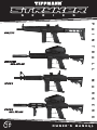
Tippmann STRYKER Le manuel du propriétaire
- Taper
- Le manuel du propriétaire

SERIES
OWNER’S MANUAL
Paintball MarkerS
02 16

2
E
N
G
L
I
S
H
F
R
A
N
Ç
A
I
S
E
S
P
A
Ñ
O
L
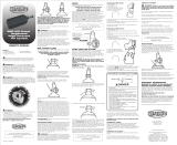
ADVERTENCIA
Esto no es un juguete. Un uso inapropiado puede causar
serias heridas o la muerte. Ojos, cara y oidos deben ser
protegidos todo el tiempo, con la protección diseñada
para paintball tanto por jugadores como por cualquier
persona que este en el radio de alcance. Recomendamos
al menos 18 años para la compra y uso. Las personas
menores de 18 años deben usar este producto bajo la
supervisión de un adulto. Lea el Manual del Usuario
antes de usar este producto.
WARNING
This is not a toy. Misuse may cause serious injury
or death. Eye, face, and ear protection designed for
paintball must be worn by the user and any person
within range. We recommend you be at least 18 years
old to purchase. Persons under 18 must have adult
supervision when using this product. Read the Owner’s
Manual before using this product.
AVERTISSEMENT
Ceci n’est pas un jouet. Une mauvaise utilisation peut
causer de sérieuses blessures ou entraîner la mort. Une
protection spécique au paintball pour les yeux, la tête
et les oreilles doit être utilisée par l’utilisateur ainsi que
par toute personne située dans le champ de tir. Nous
recommandons que l’acheteur ait au moins 18 ans. Les
personnes de moins de 18 ans doivent être surveillées
par un adulte durant l’utilisation de ce produit. Lisez le
manuel d’utilisation avant d’utiliser ce produit.

3
E
N
G
L
I
S
H
F
R
A
N
Ç
A
I
S
E
S
P
A
Ñ
O
L
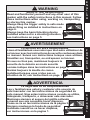
WARNING
Safety is Your Responsibility
Read and familiarize yourself and any other user of this
marker with the safety instructions in this manual. Follow
these instructions when using, working on, transporting,
or storing this marker.
Always keep the trigger safety in safe mode
unless ring as detailed in instructions on
page 6.
Always keep the barrel blocking device
installed when not in a shooting situation,
see instructions on page 5.
AVERTISSEMENT
La Securite est Votre Responsabilite
Lisez et familiarisez-vous ainsi que tout autre utilisateur de
ce lanceur avec les instructions de securite contenues dans
ce manuel. Suivez ces instructions lorsque vous utilisez,
travaillez sur, transportez, ou entreposez ce lanceur.
Si vous ne tirez pas, maintenez toujours la
securite de la detente en mode securite
comme indique dans les instructions en page 3.
Gardez toujours la douille du canon
installeed lorsque vous n’etes pas en
situation de tir, voir instructions en page 1.
ADVERTENCIA
La Seguridad es Su Responsabilidad
Lea y familiaricese usted y cualquier otro usuario de
este marcador con las instrucciones de seguridad de
este manual. Siga estas instrucciones cuando se utiliza,
trabajando, transporte, o almacenar este marcador.
Mantenga siempre el seguro del gatillo activado
a menos que sea necesario hacer disparos.
Como se ve en las instrucciones de la página 3.
Siempre mantenga la funda de seguridad
instalada cuando no va hacer disparos,
ver instrucciones en la pagina 1.

4
E
N
G
L
I
S
H
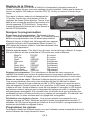
CONGRATULATIONS on your purchase of your Tippmann Stryker Series paintball marker. We
believe our Stryker Series markers to be the most accurate and durable paintball marker available.
Stryker Series markers will provide many years of dependable service if cared for properly.
Please take time to read this manual thoroughly and become familiar with your Stryker Series
marker’s parts, operation, and safety precautions before you attempt to load or re this
marker. If you have a missing or broken part, or need assistance, please contact Tippmann/GI
Sportz Customer Service at 1-800-220-3222 for fast, friendly service.
TABLE OF CONTENTS
Barrel Blocking Device Installation Instructions ......................................................................5
Warning/Liability Statement ....................................................................................................6
Safety is Your Responsibility! .................................................................................................6
Getting Started .......................................................................................................................8
1. Install the Barrel ..........................................................................................................8
2. Battery Installation ......................................................................................................8
3. High Pressure Air (HPA) Cylinder Installation .............................................................8
4. Attaching and Loading the Hopper .............................................................................9
5. Firing the Marker ........................................................................................................9
Eye Operation .........................................................................................................................9
LED Indication ................................................................................................................9
Eye Malfunction ..............................................................................................................9
Eye/LED Status Table ................................................................................................... 10
Low Battery Indicator ............................................................................................................10
Unloading Your Marker .........................................................................................................10
Velocity Adjustment ..............................................................................................................10
Programming Navigation ......................................................................................................11
Programming Menus ............................................................................................................11
High Pressure Air Cylinder Warnings ...................................................................................13
Air Cylinder Safety Tips ................................................................................................13
Air Cylinder Removal ............................................................................................................14
Repairing Air Cylinder Leaks ........................................................................................14
Cleaning and Maintenance ...................................................................................................15
Storage .................................................................................................................................15
Stryker Series Disassembly Instructions ..............................................................................16
Barrel and Shroud Assemblies .....................................................................................16
Stock Assemblies .........................................................................................................18
The Stryker Marker Exploded View .............................................................................19
Disassembly of Bolt System .........................................................................................20
Removal of Grip Frame and Regulator .........................................................................20
Regulator Disassembly and Maintenance ....................................................................21
Front and Rear Sights ..................................................................................................22
Advanced Regulator Disassembly and Maintenance ...........................................................22
Specications .......................................................................................................................23
Warranty and Repair Information .........................................................................................24
Stryker Series Paintball Markers
by
Tippmann Sports/GI Sportz
11723 Lime Kiln Road, Neosho, MO 64850 USA
1-800-220-3222

5
E
N
G
L
I
S
H
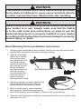
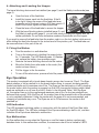
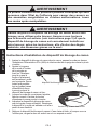
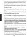
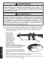
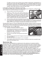
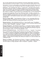
Barrel Blocking Device Installation Instructions
1. Insert the barrel blocking device onto the Barrel, and loop the cord over the Air Supply
Adapter (ASA) and position at the back of the grip as shown.
2. Adjust the cord length
retainer up to the back
of the grip by pulling
the cord through it until
the retainer is snug
against the back of the
grip. Keeping the cord
as tight as possible,
leave just enough cord
elasticity to remove
the cord/retainer from
under the marker to
remove the barrel
blocking device for ring.
3. After the cord length is properly adjusted, lock
the cord length by tying a knot in the cord
against the back of the retainer as shown.
4. Before and after playing, inspect the barrel
blocking device. Replace the barrel blocking
device if the device or cord is damaged, or there is a loss of cord elasticity.
5. Clean the barrel blocking device with plain, warm water and store out of sunlight in a dry
area when not in use.
WARNING
This product contains one or more chemicals that are known
to the State of California to cause cancer and birth defects
or other reproductive harm. Wash hands after handling.
WARNING
Always keep the barrel blocking device installed except when
your marker is in use. Always make sure that the Safety
is in the safe mode (see instructions on page 6) and the
barrel blocking device is properly installed on your marker
according to the instructions to prevent damage to property,
serious injury, or death.
Barrel Blocking Device
Cord Length
Retainer
Cord Length Retainer and Knot

6
E
N
G
L
I
S
H
Warning/Liability Statement
This marker is classied as a dangerous weapon and is surrendered by Tippmann Sports/GI
Sportz/GI Sportz with the understanding that the purchaser assumes all liability resulting from
unsafe handling or any action that constitutes a violation of any applicable laws or regulations.
Tippmann Sports/GI Sportz shall not be liable for personal injury, loss of property or life
resulting from the use of this weapon under any circumstances, including intentional, reckless,
negligent or accidental discharges.
All information contained in this manual is subject to change without notice. Tippmann Sports/
GI Sportz reserves the right to make changes and improvements to products without incurring
any obligation to incorporate such improvements into products previously sold.
If you as a user do not accept liability, Tippmann Sports/GI Sportz requests you do not use
a Tippmann Sports/GI Sportz marker. By using this paintball marker you release Tippmann
Sports/GI Sportz of any and all liability associated with its use.
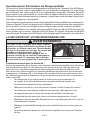
SAFETY IS YOUR RESPONSIBILITY!
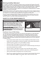
WARNING
Except when your marker is in use, always
make sure that the safety button is in safe
mode, (which disables the trigger and
electronics) and that the barrel blocking
device is properly installed (see page 5).
To turn on safe mode: push the safety button
in from this Power Button side
.
To go to re mode: push the safety button
on the side opposite of the Power Button
.
Push in here for safe mode
(re mode shown).
Familiarize Yourself With Safety...
The ownership of this weapon places upon you the total responsibility for its safe and lawful
use. You must observe the same safety precautions as you would any rearm to assure
the safety of not only yourself but everyone around you. Outlined here are some general
precautions to be aware of. The user should at all times use caution and common sense when
using this marker and always remember that the game of paintball can only survive and grow
if it remains SAFE!
• Do not load or re this marker until you have completely read this manual, and are
familiar with its safety features, mechanical operation, and handling characteristics.
• Handle this and any marker as if it were loaded at all times.
• Keep your nger off the trigger until you are ready to shoot.
• Do not look down the barrel of a paintball marker. Accidental discharge into the eyes
may cause permanent injury or death.
• Keep the marker in safe mode until ready to shoot (see Warning box above).
• Keep the barrel blocking device installed on marker when not shooting (page 5).
• Never point the marker at anything you do not intend to shoot.
• Never re your marker at anything you do not intend to shoot because there may be
balls or foreign debris lodged in the chamber, barrel, and/or the marker valve.

7
E
N
G
L
I
S
H
• Do not shoot at fragile objects such as windows.
• Never re your marker at personal property of others. The paintball impact can
cause damage and the paint can stain the nish of automobiles, houses, etc.
• Always keep the muzzle pointed down or in a safe direction, even if you stumble or
fall.
• Eye, face, and ear protection designed specically to stop paintballs in the form of
goggles and full face mask meeting ASTM Specication F 1776 must be worn by the
user and any person within range.
• Never shoot at a person who is not protected by eye, face, and ear protection
designed for paintball.
• Pressurize and load the marker only when the marker will be immediately used.
• Store the marker unloaded and degassed in a secure place.
NOTE: Before storing or disassembling, be sure to remove paintballs and air supply
(see Unloading Your Marker and Air Cylinder Removal instructions on pages 10
and 14) and install the barrel blocking device (see page 5).
• Do not eld strip or otherwise disassemble this marker while it is pressurized with air
supply.
• Dress appropriately when playing the game of paintball. Avoid exposing any skin
when playing the game of paintball. Even a light layer will absorb some of the
impact and protect you from the paintballs.
• Keep exposed skin away from escaping gas when installing or removing air cylinder
or if the marker or air supply is leaking. Compressed air can be very cold and
may cause frostbite under certain conditions. Never use any other gas than high
pressure air (HPA).
• Only use .68 caliber paintballs. Never load or re any foreign objects.
• Avoid alcoholic beverages before and during the use of this marker. Handling
markers while under the inuence of drugs or alcohol is a criminal disregard for
public safety.
• Avoid shooting an opponent at point blank, 6 feet or less.
• Familiarize yourself with instructions listed on air supply cylinder or adapter. Contact
the air supply cylinder or adapter manufacturer with any questions.
• Read the High Pressure Air Cylinder Warnings and Safety Tips on pages 13–14
before beginning the cylinder installation or removal.
• Always measure your marker’s velocity before playing paintball and never shoot at
velocities in excess of 300 feet per second (see instructions on page 10).
• Do not brandish or display this product in public as it may cause confusion and may
be a crime. Police or others may mistake this product for a real rearm. Altering the
coloration or markings required by state or federal law to make the product look
more like a rearm is dangerous and may be a crime.

8
E
N
G
L
I
S
H
Getting Started
• Eye protection designed for paintball use must be worn by the user and any person
within range.
• Do not disassemble this marker while it is pressurized.
• Do not pressurize a partially assembled marker.
• Read each step completely before performing the step.
NOTE: Carefully hand start all threaded parts when assembling, and do not overtighten, as
this may potentially strip the threaded parts.
WARNING
Install the air supply and load the hopper with paintballs only after you:
• have a barrel blocking device installed (see page 5)
• have the Safety in safe mode (see page 6).
Eye protection designed for paintball use must be worn by the user
and any person within range.
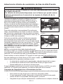
1. Install the Barrel
a. Install the Barrel and Hand Guard by turning it clockwise into the receiver.
b. Install the barrel blocking device (page 5).
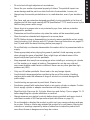
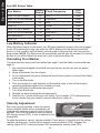
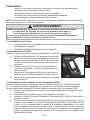
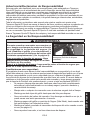
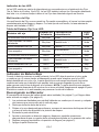
2. Battery Installation
Use these instructions for rst-time battery install or for battery replacement:
a. Use a 5/64 hex wrench to remove the two screws
from the left side grip, and open to expose the battery
compartment. NOTE: For battery replacement,
whenever removing the battery clip from the battery,
never pull it by the wires.
b. Install a 9 volt battery onto the battery clip. Observe the
polarity! Reverse polarity will damage the circuit board!
c. Insert the battery into the grip with the battery clip at the
bottom, and wires routed as shown.
d. Replace the grip and fasten with the two screws
removed in step 2a.
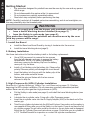
3. High Pressure Air (HPA) Cylinder Installation
Read the Air Cylinder Warnings, Safety Tips, and Removal on pages 13-14 before
beginning the HPA cylinder installation. Do not pressurize a partially assembled paintball
marker. Never use any other gas than high pressure air (HPA).
a. Put the Safety in safe mode (see page 6) and install the barrel blocking device (see
page 5).
b. Lubricate the air cylinder valve O-ring with a little Tippmann grease.
c. Insert the air cylinder valve into the Air Supply Adapter (ASA) at the back end of the
marker grip.
d. Twist the air cylinder clockwise into the ASA until it stops. Use caution as the marker is
now capable of ring after you put the Safety in a re mode. If you do not hear the full
air cylinder engage, the pin valve could be too short or the pin valve seal is damaged,
follow the Air Cylinder Removal instructions on page 14 and take your air cylinder to
a “C5” Certied Airsmith for inspection or contact the cylinder manufacturer.

9
E
N
G
L
I
S
H
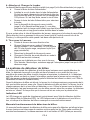
4. Attaching and Loading the Hopper
The barrel blocking device must be installed (see page 5) and the Safety in safe mode (see
page 6).
a. Open the lever of the feed tube.
b. Install the hopper neck into the feed tube. If the t
is too tight, loosen the screw of the feed tube lever
(opposite end of the lever) using a 3/32 hex wrench. If
the t is too loose, tighten the feed tube screw.
c. Close the lever of the feed tube to secure the hopper.
d. With the barrel blocking device installed (page 5), and
the Safety in safe mode (page 6), you are now ready to load your hopper with .68
caliber paintballs. Do not force excessive numbers of paintballs into the hopper.
If you want to remove the feed tube from the marker, push in on the lock button (white arrow)
while sliding the feed tube forward to the circled area of the picatinny rail. The feed tube can
be removed when in this part of the rail.
5. Firing the Marker
a. Point the marker in a safe direction.
b. Turn on the electronics by holding the power button
for 1-2 seconds. The LED ashes green. If it ashes
red, replace the battery (see previous page).
c. Remove the barrel blocking device from the marker.
d. Move the Safety from safe mode to re mode. (re
mode is shown above.)
e. Pull the trigger to re the marker.
f. To turn off the electronics, press and hold the power button until the LED turns red.
Eye Operation
This marker is equipped with a break beam breech sensor also known as “Eyes”. The Eyes
detect whether or not a paintball is in the breech before ring, to prevent chopping partially
loaded paintballs and to maximize rate of re. The Eyes can be switched on or off by tapping
the power button while the marker is powered up (the LED changes its blinking pattern when
eyes are switched on or off, see Eye/LED Status in the following Table). With the Eyes
on, the marker res up to the programmed maximum rate of re, as long as paintballs are
delivered fast enough. With the Eyes off, the marker res at the maximum rate of re whether
or not a paintball is detected. Using the marker with the eyes off is not recommended, and
chopping of paintballs may occur. The Eyes are set to ON whenever the marker is rst
powered up.
LED Indication
The LED changes its blinking pattern in conjunction with the status of the Eyes (See table
for Eye/LED status). The LED also indicates if the Eyes are detecting a ball or not, and also
indicates if the Eyes have detected a malfunction.
Eye Malfunction
An Eye malfunction occurs when the Eyes are on and the beam is broken continuously
between shots. In this malfunction condition, the maximum rate of re is limited to 5 BPS.
Power Button
LED

10
E
N
G
L
I
S
H
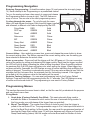
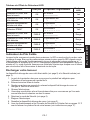
Eye/LED Status Table
Eye Status
Battery
Status
Flash Frequency
LED
Color
Eyes ON, ball in breech OK Solid ----------------------- Green
Eyes ON, No ball detected OK Slow Blink -- -- Green
Eye Malfunction OK Blink -- -- -- -- Green
Eyes OFF OK Flicker -- -- -- -- -- -- -- Green
Eyes ON, ball in breech LOW Solid ----------------------- Red
Eyes ON, No ball detected LOW Slow Blink -- -- Red
Eye Malfunction LOW Blink -- -- -- -- Red
Eyes OFF LOW Flicker -- -- -- -- -- -- -- Red
Low Battery Indicator
When the battery begins to lose power, the LED stops showing the green color and changes
to red. While performance may vary while the LED is ashing red, the electronics will still
function in this condition until the battery has lost power to the point that it will not cycle the
ring system. NOTE: The Electronics will automatically shut off after 60 minutes of no activity.
Be sure to turn off the Electronics when not in use to preserve battery life.
Unloading Your Marker
The barrel blocking device must be installed (see page 5) and the Safety in safe mode (see
page 6).
1. Eye protection designed for paintball use must be worn by the user and any person
within range.
2. Empty all paintballs from the Hopper.
3. Go to a designated ring area, remove the barrel blocking device, and move the Safety
to re mode.
4. Turn on the Electronics.
5. Point your marker in a safe direction and re several times to be sure there are no
remaining paintballs lodged in the chamber or barrel.
6. Return the Safety to safe mode (see page 6).
7. Turn off the Electronics
8. Reinstall the barrel blocking device (see page 5).
9. Read the Air Cylinder Warnings and Safety Tips on pages 13-14 before removing
the air cylinder from your marker (removal instructions - page 14).
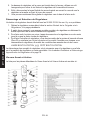
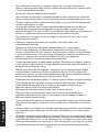
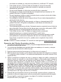
Velocity Adjustment
Each time you play paintball, check the velocity
of your paintball marker with a chronograph (an
instrument for measuring velocity) prior to playing
paintball. Verify that the marker’s velocity is set at
300 feet per second (FPS), or less if required by the
playing eld.
To adjust the marker’s velocity, use the included 1/4 hex wrench in the bottom of the vertical
regulator (white arrow). Turning the hex wrench counterclockwise (CCW) increases the
velocity (higher FPS). Turning clockwise (CW) decreases the velocity (lower FPS).

11
E
N
G
L
I
S
H
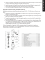
Programming Navigation
Entering Programming - Unload the marker (page 10) and remove the air supply (page
14). Never attempt to do Programming on a pressurized marker!
Turn on the marker and use a hex wrench to press and release
the Programming Button (arrow at right). The LED ashes an
array of colors. You are now in the main programming menu.
Cycling through the menu - To cycle through the menu
items, pull and release the trigger. Each time the trigger is pulled
and released, a different color code is displayed by the LED:
Firing Mode RED Solid
ROF cap GREEN Solid
Dwell AMBER Solid
Debounce RED Flicker
BIP GREEN Flicker
Ramp Start AMBER Flicker
Ramp Sustain RED Blink
Ramp Reset GREEN Blink
Burst shot count AMBER Blink
Current Value - Upon selecting a menu item, press and release the power button to show
the current setting value. The ashes represent the current setting value; see the setting you
have selected to determine the actual value.
Enter a new value - Press and hold the trigger until the LED goes out. You can now enter
value of the setting by pulling and releasing the trigger quickly. Each time the trigger is pulled
the LED will light up green indicating the value is being increased. When the setting reaches
its maximum limit, the LED glows an Amber color when pulling the trigger. When trigger has
not been pulled for 3seconds, the LED ashes an array of colors indicating that modifying the
setting is stopped. The setting is automatically saved. If the new value entered is less than the
minimum limit for that menu item, the minimum limit for that setting is saved. If the trigger is
not pulled at all, the minimum value for that setting will be saved
Reset to Factory Settings - You can reset programming back to the Factory Default
Settings. Press and hold the programming button for 6-7 seconds. The LED ashes an array
of colors and the board shuts off. The programming is now reset to Factory Default.
Programming Menus
This section discusses the menu items in detail, so that the user fully understands the purpose
and use of each menu item.
Firing Mode
1. Semi-Auto (Factory Default) One Blink
- This semi-automatic ring mode is
available for elds or tournaments which restrict the use of automatic ring modes. In
this ring mode, one pull/release of the trigger res one paintball.
2. Burst* Two Blinks - The marker res a burst of shots for each time the trigger is
pulled at the set Rate of Fire. The programmable range is 2 to 6 shots per burst which is
set by the Burst Shots setting. In Burst mode, the user must re programmed number of
times set by Ramp Start setting (page 12) with time between each trigger pull less than
Ramp Reset setting (below) then the marker will enter Burst and re number of shots

12
E
N
G
L
I
S
H
determined by Burst Shot setting (below). Ramp Start shot count will reset after not
ring for the amount of time set by the Ramp Reset setting.
3. Ramp* Three Blinks - If ring the programmed number of times set by Ramp Start
setting and at a rate of trigger pulls per second set by Ramp Sustain setting, then the
marker will re at the maximum set Rate of Fire determined by the ROF Cap setting.
Ramp Start count is reset after not ring for amount of time determined by the Ramp
Reset setting or the Ramp Sustain setting if Ramp Reset is set to 0.
4. Full-Auto* Four Blinks - In Full Auto mode, the user must re the programmed
number of times set by Ramp Start setting with the time between each trigger pull
being less than Ramp Reset setting then marker will enter full auto and re as long as
the user holds down the trigger. Ramp Start shot count will reset after not ring for the
amount of time set by Ramp Reset setting.
The * indicates an enhanced ring mode, requiring at least 3 trigger pulls before the enhanced
ring mode engages. The Ramp Start setting allows users to adjust the number of shots
required to engage.
ROF Cap - (Factory Default Value = 10 BPS) This is the programmed maximum Rate of re
(RoF) in balls per second (BPS). The ROF can be set from 5-10 BPS where 1 blink = 1 BPS).
Dwell - (Factory Default Value = 35 milliseconds (ms); 35 blinks) The Dwell is used to change the
amount of time that power is supplied to the solenoid. The solenoid is the part of the electronics
which actually channels the ow of air to the front of the bolt allowing the marker to re. This
setting directly affects the battery life. Too high of a value will negatively affect battery life. Too
low of a value will may not allow the marker to fully cycle causing low velocity. This setting can
be adjusted from 1-60 ms.
Debounce - (Factory Default Value = 7 milliseconds; 7 blinks) The Debounce menu item is
used to change the amount of time between accepted trigger pulls. Quite simply, this adjusts
the amount of time from one trigger pull being accepted by the electronics to the next trigger
pull that can be accepted. If a Debounce setting is too low, a user may shoot more times than
expected. This is called “Trigger Bounce.” When a paintball marker is red, the marker moves
and vibrates in the user’s hand. This vibration sometimes allows the trigger to reset itself and
trip without the user realizing that his or her nger has actually moved. This menu item can be
updated only with values of 1-50 milliseconds.
Ball in Place (BIP) - (Factory Default Value = 5 ms; 5 blinks) This is the amount of time in
milliseconds that the Eyes must “see” the paintball before ring it. This menu item can be set
from 1 ms to 50 ms.
Ramp Start - (Factory Default Value = 3 trigger pulls; 3 blinks) Number of shots that must
happen before enhanced ring mode kicks in. Limit: 3-8 shots, 1 blink = 1 shot.
Ramp Sustain - (Factory Default Value = 3 trigger pulls per second; 3 blinks) Number of trigger
pulls per second (TPS) that must occur to sustain ramping. This setting only affects the Ramp
ring mode. Limit: 1-12 TPS, # of blinks = TPS.
Ramp Reset - (Factory Default Value = 1 second; 10 blinks) Amount of time after last shot until
Ramp Start shots reset to 0. Limit 0-1 second in tenths of a second. Time = # of blinks x 0.1.
When Ramp Reset is set to 0, Burst and Full Auto re modes will not be allowed to enter the
enhanced state, and will not burst re. When Ramp Reset is set to 0 in Ramp mode, the Ramp
Sustain setting is used to reset the Ramp Start shot count.
Burst Shot - (Factory Default Value = 3 shots; 3 blinks) Number of shots that the marker res
for each trigger pull when in enhanced ring mode Burst. Limit: 2-6 shots, 1 blink = 1 shot.

13
E
N
G
L
I
S
H
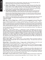
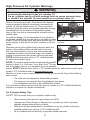
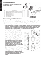
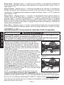
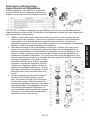
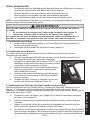
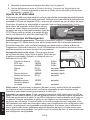
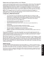
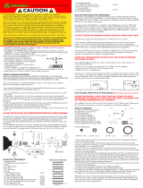
High Pressure Air Cylinder Warnings
WARNING
The brass or nickel plated cylinder valve (#1) is intended to be
permanently attached to the air cylinder (2).
An air cylinder can y off with enough force to cause serious injury
or death if the cylinder (2) unscrews from a cylinder valve (1).
Refer to the top image at right. There have been reported
incidents caused by players unknowingly unscrewing the
cylinder (2) from the cylinder valve (1). This occurs when
the player thinks the entire valve-cylinder assembly is being
unscrewed from the air adapter of the paintball marker,
when in fact he or she is unscrewing the cylinder from the
cylinder valve.
To avoid this danger, it is recommended (if your cylinder is
not already marked) that you use paint or nail polish to place
a mark (3) on the cylinder valve, and place another mark (4)
on the cylinder, in line with the #3 mark as shown in the top
image.
Whenever you turn the cylinder during removal, watch the
marks on the cylinder and the cylinder valve to be sure
that they rotate together. If at any time these marks start
to separate as shown in the bottom image, the cylinder is
starting to unscrew from the cylinder valve and you must
STOP and take the entire unit to a “C5” certied airsmith
for safe removal and/or repair.
NOTE: The cylinder valve should unscrew from the paintball
marker in about 3 or 4 full turns. If you nish the 4
th
full turn
and the cylinder valve is not unscrewed from the paintball
marker, STOP! Take the entire unit to a “C5” certied airsmith for safe removal and/or repair.
Locate a “C5” Certied Airsmith at www.paintball-pti.com.
Whether you have a new or used rellable air cylinder, you are at risk if any of the following
has occurred:
• The valve unit was replaced or altered after purchase.
• The valve unit was removed from the cylinder for any reason.
• Any modication was done to the rellable HPA cylinder.
If any of these conditions has occurred, take your air cylinder to a “C5” Certied Airsmith for
inspection or contact the cylinder manufacturer.
Air Cylinder Safety Tips
SAFETY TIPS to ensure that your air cylinder is safe for play:
• Never use any other gas than high pressure air (HPA).
• Improper use, lling, storage, or disposal of air cylinder may result in property
damage, serious personal injury or death.
• Make sure that any maintenance or modication to any air cylinder is done by a
qualied professional, such as a “C5” certied airsmith.
• All air cylinders must be lled only by properly trained personnel.
Properly Marked Valve and
Cylinder
1
3
4
2
Misaligned Valve and Cylinder
3
4

14
E
N
G
L
I
S
H
• Cylinder valves must be installed or repaired only by properly trained personnel.
• Do not overll a cylinder! Never exceed the air cylinder’s capacity.
• Do not expose pressurized air cylinder to temperatures exceeding 130 degrees
Fahrenheit (55 degrees Celsius).
• Do not use caustic cleaners or strippers on the air cylinder or cylinder valve and do
not expose to corrosive materials.
• Do not modify the air cylinder in any way. Never try to disassemble the cylinder
valve from the air cylinder.
• Any air cylinder that has been exposed to re or heated to a temperature of 350
degrees Fahrenheit (177 degrees Celsius) or more must be destroyed by properly
trained personnel.
• Use appropriate gas for your cylinder. Only use compressed air in a compressed air
cylinder. Never use any other gas than high pressure air (HPA).
• Keep all cylinders out of the reach of children.
• The air cylinder should be inspected and hydrostatically retested at least every 5
years by a DOT licensed agency.
• Keep exposed skin away from escaping gas when installing or removing the air
cylinder, or if the marker or air cylinder is leaking. Compressed air is very cold, and
can cause frostbite under certain conditions.
NOTE: Locate a “C5” certied airsmith at www.paintball-pti.com.
Air Cylinder Removal
1. Read Air Cylinder Warnings (page 13) and Air Cylinder Safety Tips (page 13-14)
before beginning the cylinder removal process.
2. Eye protection designed for paintball use must be worn by the user and any person within
range.
3. Follow the Unloading Your Marker instructions on page 10.
4. Watch the marks on the cylinder and cylinder valve as you turn the cylinder approximately
¾ turn counterclockwise. This allows the air valve pin to close so that no air will enter the
marker.
5. Remove the barrel blocking device. Set the Safety to re mode. Point the marker in a
safe direction, and discharge the remaining gas in the marker by repeatedly pulling the
trigger until the marker stops ring (this may take 4-5 shots). If your marker continues to
re, the cylinder’s pin valve has not closed yet. The cylinder pin valve could be longer than
usual. Because of the variances in cylinder pin valve parts, each cylinder varies slightly
on exactly how far it has to be turned. Turn the cylinder counterclockwise a little further
and repeat this step until the marker does not re. Only then remove the air cylinder.
NOTE: If during this step, you turned the air cylinder and it began to leak before you pulled
the trigger, the cylinder O-ring should be checked for damage before any re-assembly (see
Repairing Air Cylinder Leaks below).
6. After the air cylinder is removed, again point and re the marker in a safe direction to verify
the marker is completely discharged of gas.
7. Move the Safety to safe mode (see page 6) and install the barrel blocking device (see
page 5).
Repairing Air Cylinder Leaks
The most common leak occurs from a bad air valve O-ring. To replace a valve O-ring you must
rst remove the bad O-ring and then install a new one. This O-ring is located on the tip of your
air valve. The best valve O-rings are made of urethane. Urethane O-rings are not affected by

15
E
N
G
L
I
S
H
high air pressures. These may be purchased from Tippmann or your local paintball dealer.
There is an extra O-ring in the Accessory Pack that came with your marker.
NOTE: If a new air valve O-ring does not resolve an air leak, do not attempt to repair the air
cylinder. Contact Tippmann Sports/GI Sportz, your local paintball dealer, or a “C5” Certied
Airsmith.
Cleaning and Maintenance
• To reduce the chance of an accidental discharge, follow the Unloading Your
Marker
(on page 10) and Air Cylinder Removal (on page 14).
• Eye protection must be worn.
• Do not disassemble a marker while it is pressurized with air.
• Do not pressurize a partially assembled marker.
• Follow warnings listed on the HPA cylinder for handling and storage.
• Familiarize yourself with instructions listed on air cylinder.
• Contact the air cylinder manufacturer with any questions.
• Do not use any petroleum based cleaning solvents.
• Do not use any cleaning solvents that come in aerosol cans.
NOTE: Petroleum based products and aerosol products can damage your marker’s
O-rings.
To clean the exterior of your paintball marker, use a damp towel to wipe off paint, grease,
and any debris. To clean the inside of the barrel, remove the barrel by unscrewing it from the
Receiver. Insert the tab end of the cable squeegee into barrel. Pull the squeegee through the
barrel to remove debris and paint.
General maintenance on your marker should be performed every 8000-10,000 shots or before the
start of each day of play, whichever comes rst. To perform general maintenance remove the bolt
system as explained in Stryker Series Disassembly Instructions section under Disassembly
of Bolt System
. Apply silicon based grease (Dow 33 or similar) to specic areas in the parts
diagram. This will keep your marker is good working condition. It is unnecessary to disassemble
the rest of your marker for general maintenance. Inspect the air supply valve O-ring, and lubricate
it with a little grease when attaching the air supply cylinder.
Storage
Before storage, unload the marker (page 10) and remove air cylinder (see page 14). Ensure
the Safety is in safe mode (see page 6) and the barrel blocking device is installed (see page
5). Store your marker in a dry area.
When removing your marker out of storage, make sure to keep the Safety in safe mode (see
page 6) and keep the barrel blocking device installed (see page 5).

16
E
N
G
L
I
S
H
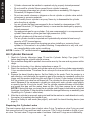
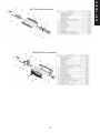
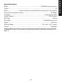
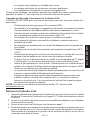
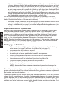
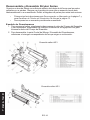
XR1 Barrel Assembly
MP1 Barrel Assembly
Stryker Series Disassembly Instructions
Set up a workbench with plenty of workspace to make sure no small parts become lost.
Always wear eye protection when performing any marker disassembly or re-assembly. Refer
to the Parts Diagrams for these instructions.
• Follow Unloading Your Marker on page 10 and Air Cylinder Removal
instructions on page 14.
• Do not pressurize a partially assembled paintball marker.
Barrel and Shroud Assemblies
1. To remove the Barrel, simply unscrew the Barrel from the Body Assembly, and to
reinstall it, just turn it clockwise to thread it into the Body Assembly.
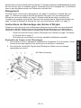
2. To disassemble the Front Grip/Shroud Assembly, refer to the appropriate image of
those that follow:

17
E
N
G
L
I
S
H
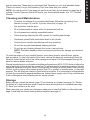
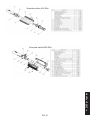
AR1 Elite Barrel Assembly
MP2 Elite Barrel Assembly

18
E
N
G
L
I
S
H
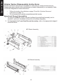
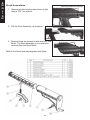
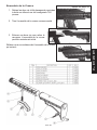
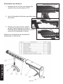
Stock Assemblies
1. Remove two hex head screws shown at right
using a 7/64” hex wrench.
2. Pull the Stock Assembly out as shown.
3. Remove these two screws to take apart the Shell
Backs. The Stock Assembly is now able to be
removed from the Stock Backs.
Refer to the Stock assembly diagrams that follow:
Remove these two screws.
Remove these two screws.

19
E
N
G
L
I
S
H
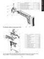
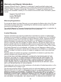
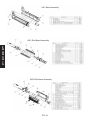
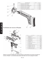
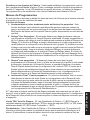
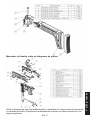
Use the diagram above to disassemble and reassemble these main components of the
Stryker Marker. The subassembly parts diagrams are on the following pages.
The Stryker Marker Exploded View

20
E
N
G
L
I
S
H
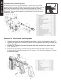
Disassembly of Bolt System
Remove stock and rear shroud assembly by removing two hex head
screws (shown on page 18). Use a hex wrench or your hand to unscrew
back cap from marker body. When removing the back cap, the bolt
may be left inside the body. The bolt can be pulled out from the rear of
the marker. You can perform general maintenance like lubricating and
replacing O-rings.
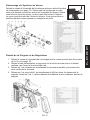
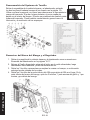
Removal of Grip Frame and Regulator
1. Remove stock and rear shroud assembly as shown in Stock Assemblies on page 18.
2. Remove the feedneck by pressing the button on the feedneck then sliding it forward and
off the rail system.
3. Remove the 3 remaining screws holding the body shell together then remove the two
body shell halves.
4. Remove the 2 screws on the bottom of the ASA that hold the ASA in place. On the
bottom side of the grip frame remove the 2 screws, 1 just above the trigger and 1 above
and behind the grip.
La page est en cours de chargement...
La page est en cours de chargement...
La page est en cours de chargement...
La page est en cours de chargement...
La page est en cours de chargement...
La page est en cours de chargement...
La page est en cours de chargement...
La page est en cours de chargement...
La page est en cours de chargement...
La page est en cours de chargement...
La page est en cours de chargement...
La page est en cours de chargement...
La page est en cours de chargement...
La page est en cours de chargement...
La page est en cours de chargement...
La page est en cours de chargement...
La page est en cours de chargement...
La page est en cours de chargement...
La page est en cours de chargement...
La page est en cours de chargement...
La page est en cours de chargement...
La page est en cours de chargement...
La page est en cours de chargement...
La page est en cours de chargement...
La page est en cours de chargement...
La page est en cours de chargement...
La page est en cours de chargement...
La page est en cours de chargement...
La page est en cours de chargement...
La page est en cours de chargement...
La page est en cours de chargement...
La page est en cours de chargement...
La page est en cours de chargement...
La page est en cours de chargement...
La page est en cours de chargement...
La page est en cours de chargement...
La page est en cours de chargement...
La page est en cours de chargement...
La page est en cours de chargement...
La page est en cours de chargement...
La page est en cours de chargement...
La page est en cours de chargement...
La page est en cours de chargement...
La page est en cours de chargement...
La page est en cours de chargement...
La page est en cours de chargement...
La page est en cours de chargement...
La page est en cours de chargement...
La page est en cours de chargement...
La page est en cours de chargement...
La page est en cours de chargement...
La page est en cours de chargement...
La page est en cours de chargement...
La page est en cours de chargement...
La page est en cours de chargement...
La page est en cours de chargement...
-
 1
1
-
 2
2
-
 3
3
-
 4
4
-
 5
5
-
 6
6
-
 7
7
-
 8
8
-
 9
9
-
 10
10
-
 11
11
-
 12
12
-
 13
13
-
 14
14
-
 15
15
-
 16
16
-
 17
17
-
 18
18
-
 19
19
-
 20
20
-
 21
21
-
 22
22
-
 23
23
-
 24
24
-
 25
25
-
 26
26
-
 27
27
-
 28
28
-
 29
29
-
 30
30
-
 31
31
-
 32
32
-
 33
33
-
 34
34
-
 35
35
-
 36
36
-
 37
37
-
 38
38
-
 39
39
-
 40
40
-
 41
41
-
 42
42
-
 43
43
-
 44
44
-
 45
45
-
 46
46
-
 47
47
-
 48
48
-
 49
49
-
 50
50
-
 51
51
-
 52
52
-
 53
53
-
 54
54
-
 55
55
-
 56
56
-
 57
57
-
 58
58
-
 59
59
-
 60
60
-
 61
61
-
 62
62
-
 63
63
-
 64
64
-
 65
65
-
 66
66
-
 67
67
-
 68
68
-
 69
69
-
 70
70
-
 71
71
-
 72
72
-
 73
73
-
 74
74
-
 75
75
-
 76
76


Tippmann STRYKER Le manuel du propriétaire
- Taper
- Le manuel du propriétaire
dans d''autres langues
- English: Tippmann STRYKER Owner's manual
- español: Tippmann STRYKER El manual del propietario
Documents connexes
-
Tippmann 98 Custom PS Le manuel du propriétaire
-
Tippmann X7 PHENOM Le manuel du propriétaire
-
-
-
-
-
-
-
-
Tippmann TMC .50Cal Le manuel du propriétaire
Autres documents
-
 G.I. Sportz LVL LOADER Le manuel du propriétaire
-
 Piranha 08 Plus Rampage Le manuel du propriétaire
-
 WGP 141846-HPA_ Le manuel du propriétaire
-
JT HPA Le manuel du propriétaire
-
BT / Empire Battle Tested BT-4 Le manuel du propriétaire
-
Empire G1 Regulator Le manuel du propriétaire
-
Cobra Universal Sportz-Comm Le manuel du propriétaire
-
-
 Pure Energy HPA Le manuel du propriétaire
-


