Ascon tecnologic VP Le manuel du propriétaire
- Taper
- Le manuel du propriétaire

Einbau- und Betriebsanleitung
Installation and Operating instructions
Instructions de montage et de service
Elektropneumatischer Stellungsregler
Electropneumatic positioner
Régulateur-positionneur électro-pneumatique
6139-8010
SR 1000 L (RTK)
12/2010
D
GB
Inhaltsverzeichnis
1 Einführung 3
2 Herstellergarantie 3
3 Produktbeschreibung 3
3.1 Hauptmerkmale und Funktionen 3
3.2 Funktionsweise 3
3.3 Typenschildangaben 4
3.4 Technische Daten 4
3.5 Einzelteile 5
3.6 Maße 5
4 Montage 6
4.1 Sicherheitswarnung 6
4.2 Montagewerkzeuge 6
4.3 SR 1000 L Montage 6
4.4 Normteile 6
4.5 Montageschritte 9
5 Verrohrung 9
5.1 Zustand der Versorgungsdruckluft 9
5.2 Zustand der Luftleitung 9
5.3 Rohrleitungsverbindung mit dem Antrieb 9
6 Stromanschluß 9
6.1 Kabelanschluß 9
7 Einstellung 10
7.1 Einstellung des Nullpunktes 10
7.2 Einstellung der Hubweite 10
7.2 Einstellung des A/M Schalters (Auto/Manual) 10
7.3 Anpassen der Blende 11
8 Problembehandlung 12
Table of Contents
1 Introduction 3
2 Manufacturer warranty 3
3 Product description 3
3.1 Main features and functionalities 3
3.2 Functionality 3
3.3 Nameplate specifications 4
3.4 Technical specifications 4
3.5 Components 5
3.6 Dimensions 5
4 Assembly 6
4.1 Safety precations 6
4.2 Assembly tools 6
4.3 SR 1000 L assembly 6
4.4 Standard parts 6
4.5 Assembly ´ 9
5 Tubing 9
5.1 Compressed air supply condition 9
5.2 Air line condition 9
5.3 Connecting the pipe to the drive 9
6 Electrical connection 9
6.1 Air line condition 9
7 Adjustments 10
7.1 Setting the zero point 10
7.2 Adjusting the stroke width 10
7.3 Adjusting the A/M switch (auto/manual) 10
7.4 Adjusting the cover 11
8 Troubleshooting 12

Einbau- und Betriebsanleitung
Installation and Operating instructions
Instructions de montage et de service
6139-8010
02/2010 2
FR
Sommaire
1 Introduction 3
2 Garantie du fabricant 3
3 Description du produit 3
3.1 Principales caractéristiques et fonctions 3
3.2 Mode de fonctionnement 3
3.3 Données des plaques signalétiques 4
3.4 Données techniques 4
3.5 Pièces 5
3.6 Dimensions 5
4 Montage 6
4.1 Avertissement de sécurité 6
4.2 Outil de montage 6
4.3 Montage SR 1000 L 6
4.4 Pièces normalisées 6
4.5 Étapes de montage 9
5 Tuyauterie 9
5.1 État de l'air comprimé d'alimentation 9
5.2 État de la conduite d'air 9
5.3 Raccordement de la conduite avec l'entraînement 9
6 Connexion électrique 9
6.1 Raccordement du câble 9
7 Réglage 10
7.1 Ajustement du point zéro 10
7.2 Ajustement de la longueur de levage 10
7.3 Réglage de l'interrupteur A/ M (automatique/manuel) 10
7.4 Ajustement du diaphragme 11
8 Dépannage 12

Einbau- und Betriebsanleitung
Installation and Operating instructions
Instructions de montage et de service
6139-8010
02/2010 3
1 Product labelling
Thank you for purchasing this RTK product. Each product is thoroughly inspected following production to provide you with the highest level quality. To ensure
you will be able to utilise this product to its full capacity we strongly advise users to carefully read the operator’s manual.
• The operator’s manual should be included in the delivery to the customer.
• The operator’s manual is subject to change or review without prior notice. Changes in the product specification, product structure and/or the
product components will not necessarily result in a modification of the operator’s manual.
• Do not copy or reproduce the operator’s manual for any purpose without the approval of Regeltechnik Kornwestheim GmbH.
2 Manufacturer warranty
• To ensure safety always follow the instructions contained in the operator’s manual. The manufacturer assumes no liability for damages due to
failure to follow instructions.
• The manufacturer is not liable for damages or accidents caused by a modification of the product or its components. In the event a modification is
required, please contact the manufacturer directly.
• Improper use will void the warranty
• For detailed warranty information please contact Regeltechnik Kornwestheim GmbH directly.
3 Product description
3.1 Main features and functionalities
• Developed for high performance and robustness. Suitable for use in high vibration environments.
• Robustness proven with at least 1 million test cycles.
• Reaction time is very small and accurate
• Adjustment of ½ split range through simple parts exchange
• Low air consumption for efficiency
• Easy to adjust direct / reverse action.
• Easy to adjust zero and stroke width
• Easy to implement feedback connection
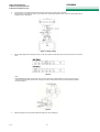
3.2 Functionality
<Image1>
If the supply pressure rises the flapper (2) moves the jet (3), increasing the space between the jet (3) and the flapper (2) resulting compressed air escaping from
the upper spool (5). This in turn causes a downward movement of the spool (5). If the spool moves upward the actuator (10) is supplied with compressed air. The
increase in pressure causes the drive screw (12) to move. The movement is transferred to the cam (14), creating traction on the stroke width spring (16). The
traction of the stroke width spring (16) is compensated by the lift drive. This moves the flapper (2) into its normal position, minimising the space between the jet
(3). When the air pressure drops at the jet outlets (3) the pressure again increases at the spool (5). The spool (5) would return to its normal position and attempt
to block its position (7), which would break the compressed air supply for the drive (10). If the drive (10) adjusts the motion the positioner returns to its regular
position.
3.3 Nameplate specifications

Einbau- und Betriebsanleitung
Installation and Operating instructions
Instructions de montage et de service
6139-8010
02/2010 4
3.4 Technical Specifications
Category SR 1000 L
Input signal 4-20mA DC
Internal resistance 250±15Ω
Supply air pressure 1.4-7.0 bar (20-100 PSI)
Stroke 10 - 60mm*
Air connection G(NPT) 1/4
Pressure gauge connection G (NPT) 1/8
Cable entry G 1/2 or PF 1/2
Protection class IP66
Ambient temperature minus 20°C to +70°C
Linearity ±1.0%
Hysteresis 1.0%
Material Die cast aluminium
Weight 2.7 kg
* Special lengths available upon request

Einbau- und Betriebsanleitung
Installation and Operating instructions
Instructions de montage et de service
6139-8010
02/2010 5
3.5 Components
3.5 Dimensions

Einbau- und Betriebsanleitung
Installation and Operating instructions
Instructions de montage et de service
6139-8010
02/2010 6
4. Assembly
4.1 Safety precautions
Please follow the safety precautions during assembly.
• The compressed air supply for the valve, drive and other equipment must be shut off.
• Use a bypass valve or other equipment to avoid a complete system failure
• Ensure there is no compressed air connected with the drive
4.2 Assembly tools
1 Hexagonal spanner
2 Phillips screwdriver
3 Hex screw spanner
4.3 SR 1000 L assembly
SR 1000 L should be connected to valves with linear movement such as gate- or check valves, moved by pneumatic force.
Be sure to have the following components available prior to assembly.
1 SR 1000 L
2 Lever and spiral spring
3 Retaining plate
4 Guide rail
5 Actuating pin
4.4 Standard parts
1 DIN 933 hexagonal screw M8 x 16 (6x)
2 DIN 125 washer 8 (6x)
3 DIN 933 hexagonal screw M5 x 10 (2x)
4 DIN 125 washer 5 (2x)
5 DIN 7980 lock washer 5 (2x)
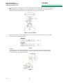
4.5 Assembly
1. Mount the lever with a M5 nut and secure with a round-head screw to prevent turning.
Figure 2 Figure 3

Einbau- und Betriebsanleitung
Installation and Operating instructions
Instructions de montage et de service
6139-8010
02/2010 7
2. Mount the guide rail to the parallel guide using two M5x10 hexagonal screws and two washers and two lock screws. Place the washers between the
lock washers and the parallel guide. See figure 4
Figure 4
3. Mount the retaining plate to the SR 1000 L using two M8x16 hexagonal screws on the connecting flange. See figure 5
4. Secure the spiral spring to the lever. See figure 6
5. Secure the actuating pin on the guide rail but do not yet tighten the M5 nut. The actuating pin is pressed from the spring onto the side of the
slot inside the lever. This allows for movement without clearance. See figure 5
Figure 5
Figure 6

Einbau- und Betriebsanleitung
Installation and Operating instructions
Instructions de montage et de service
6139-8010
02/2010 8
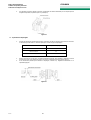
6. Connect the drive to a compressed air supply. Move the drive screw to the 50% stroke position. See figure 7
7. In this position move the guide rail upward or down until the lever of the position regulator is level. Once in this position tighten the two
hexagonal screws on the guide rail.
Figure 7- spring closing
8. Slide the spiral spring and the actuating pin until it is in the correct position and the right stroke (see figure 8) has been set on the lever
scale.
Figure 8
Note:
After assembling the SR 1000 L move the drive from 0% to 100% of the stroke. In both positions at 0% and 100% the lever may not
touch the end stop at the back of the SR 1000 L. See figure 9. If there is contact with the end stop move the actuating pin toward the
pivot point of the lever.
Figure 9
9. With the actuating pin in its correct position tighten the hexagonal nut on the actuating pin.

Einbau- und Betriebsanleitung
Installation and Operating instructions
Instructions de montage et de service
6139-8010
02/2010 9
5. Tubing
Note:
• Select a suitable compressor as the compressed air supply to prevent moisture, oil or dust from entering.
• We recommend installing a pressure regulator before the SR 1000 L supply pressure input.
5.1 Compressed air supply condition
1. Dry air with a temperature at least 10°C below the ambient temperature.
2. Avoid dusty air. The filter can only screen out particles 5 microns or larger.
3. Avoid any oil contamination.
4. Be sure to observe the pressure equipment guideline.
5. Do not set the regulator beyond 1.4 – 6 bar.
6. Set the supply pressure on the air filter regulator 10% higher than the controlled range of the pneumatic drive.
5.2 Air line condition
1. Be sure the line is empty.
2. Never use kinked or ruptured tubes or pipes.
3. Use a line with an inside diameter greater than 4 mm to ensure the proper flow rate
5.3 Connecting the pipe to the drive
On a single-acting SR 1000 L use the output OUT1. When using a one-way drive where the springs set the initial state, connect output
OUT1 with the drive.
Figure 10- spring opens
6. Electrical connection
6.1 Air line condition
1. Open the front cover.
2. Locate the poles and connect accordingly. Be sure all screws are tightened.
3. Close the cover. See figure 11
4. Only feed the cable into the housing with the appropriate cable fitting and secure.
Figure 11

Einbau- und Betriebsanleitung
Installation and Operating instructions
Instructions de montage et de service
6139-8010
02/2010 10
Safety precaution
SR 1000 L has been developed according to the mandatory guidelines of inherently safe systems. However, inherently sable systems can be
damage by electric energies of other electronics. Please read the following to prevent any system damage:
• Isolate one inherently safe circuit from another.
• Construct a device to minimise friction.
• If possible, reduce the use of induction and capacity.
When application allows, set the devices to a value below the maximum.
• Protect cables from damage.
• Earth correctly per the field method.
For earthing connections see figure 11.
7. Adjustments
7.1 Setting the zero point
1. Set the input signal to 4 mA or 20 mA and turn the adjustment wheel clockwise or counter-clockwise to set the starting point
of the drive. When setting the zero point be sure to allow for the specifications of the valve and the system. Please note
figure 12 on increasing or lowering the zero point.
Figure 12
7.2 Adjusting the stroke width
1. After setting the zero point set the input signal to 20 mA or 4 mA. Check the drive stroke. If the stroke is too small, adjust the
stroke width toward ‘+’. If the stroke is too high adjust the stroke width toward ‘-‘. Figure 13
Figure 13
2. Adjusting the stroke width will impact the zero point setting. This means the zero point needs to be adjusted. Check the
stroke width after setting the zero point. Repeat this step until both points are correctly adjusted.
3. After completing the adjustment tighten the set screw. Figure 11
7.3 Adjusting the A/M switch (auto/manual)
1. The A/M switch will set the valve function to automatic or manual.
2. The SR 1000 L factory preset is “A (automatic)”. If the user needs the regulator setting to be “M (manual)“ it can be set by
turning the switch counter-clockwise. Figure 12.
3. Switching the regulator to "M (manual)” will directly supply the drive with compressed air. Be sure to always reset to „A
(automatic) after changing this setting.

Einbau- und Betriebsanleitung
Installation and Operating instructions
Instructions de montage et de service
6139-8010
02/2010 11
Figure 14
7.4 Adjusting the cover
1. If the drive size is relatively small compared to the flow rate the regulator may begin to swing. Any swinging clan be
prevented through the use of covers. There are three types of covers.
Drive size Cover size
90 cm³ or less ø1
90 cm³ to 180 cm³ ø2
180 cm³ none
2. Remove the O-ring from the OUT1 output and install the corresponding cover. After attaching the cover set the O-ring back.
Be sure no foreign objects enter the input. Figure 13
3. If swinging continues after inserting the cover, please contact Regeltechnik Kornwestheim or a suitable representative.
Figure 15

Einbau- und Betriebsanleitung
Installation and Operating instructions
Instructions de montage et de service
6139-8010
02/2010 12
8. Troubleshooting
¾ Position regulator doesn’t respond to the input signal.
1. Check the supply pressure level, which must be at least 1.4 bar. On drives with return springs the pressure
must be higher than the total spring force.
2. Return springs - verify the input signal is routed correctly on the position regulator. The signal should be 4-20 mA
DC.
3. Verify the zero point and stroke range are correctly set.
4. Check the jet on the position regulator for blockages. Also verify the compressed air is in contact with the
regulator and air is being emitted from the jet. If the jet was blocked please return the product for repair.
5. Verify the lever is installed correctly.
¾ Pressure at the OUT1 output reaches the output pressure but doesn’t drop.
1. Check the A/M switch. If the switch is damaged replace the switch or install a relay.
2. Check the space between the armature shaft and jet and check the mechanism for damage. If damaged,
please send the product to Regeltechnik Kornwestheim for repair.
¾ Air only escapes from the A/M switch.
1. Check the regulator jet for blockages. Verify the compressed air is in contact with the regulator and
compressed air is being emitted from the jet. If the jet is blocked please return the product for repair.
¾ Swinging regulator
1. Check if the locking spring is dislocated. (Next to the pilot relay valve).
2. Check if the drive is too small. If so, install a cover to reduce the flow rate.
3. Check for excessive friction between the drive and the valve. If so, install a larger drive or reduce the friction
level.
¾ The drive will only operate on On/Off.
1. Check the functionality of the drive and regulator. On the SR 1000 L compressed air will escape from output
OUT1 as the input signal increases. Thus it is standard practice to connect to output OUT1 when using a
single-acting drive. Verify the stroke width is correctly set according to the valve system.
¾ Linearity too low.
1. Check if the regulator is installed correctly. Particularly verify the lever is horizontal at 50% stroke.
2. Verify the zero point and stroke width are set correctly. If a value is adjusted the other must be readjusted.
3. Verify the compressed air supply is solid. If not, replace the compressed air regulator.
¾ Hysteresis too low.
1. Clearance may exist if the lever and the spiral spring are loose. To avoid clearance, adjust the spiral spring.
2. Verify if the actuating pin is connected to the lever without clearance.

Einbau- und Betriebsanleitung
Installation and Operating instructions
Instructions de montage et de service
6139-8010
02/2010 13
1 Identification du produit
Merci d'avoir décider d'acheter ce produit RTK. Chaque produit est soigneusement inspecté après la production, afin de vous offrir la plus haute qualité. Pour
obtenir le rendement maximal de ce produit complet, nous conseillons vivement aux utilisateurs de lire soigneusement ses instructions.
• Les instructions d'utilisation doivent être fournies à l'utilisateur final.
• Les instructions d'utilisation peuvent être modifiées ou révisés à tout moment sans préavis. Les modifications dans les spécifications du produit, de
la structure du produit et/ou des composants du produit ne doivent pas nécessairement se refléter dans les instructions d'utilisation.
• Les instructions d'utilisation ne doivent pas être copiés ou reproduites indépendamment de l'objectif sans la permission de Regeltechnik
Kornwestheim GmbH.
4 Garantie du fabricant
• Pour garantir la sécurité il est nécessaire de suivre les instructions figurant dans le manuel. Le fabricant n'est pas responsable des dommages
causés par négligence.
• Le fabricant n'est pas responsable des dommages ou accidents qui ont été causés par l'altération du produit et de ses différentes parties. Si un
changement est nécessaire, contacter s.v.p. directement le fabricant.
• L'utilisation inappropriée ne sera pas couverte par la garantie
• Pour des d'informations plus détaillées sur la garantie, s'il vous plaît contactez Regeltechnik Kornwestheim GmbH
5 Description du produit
3.6 Caractéristiques principales et fonctions
• Conçu pour une haute performance et robustesse. Adapté pour une utilisation dans des environnements avec des vibrations fortes.
• La robustesse a été démontrée avec au moins 1 million de cycles d'essai.
• Le laps de temps de réponse est très réduit et précis
• Réglage de la ½ Split Range en remplaçant simplement les pièces
• Économique en raison de sa faible consommation d'air
• Les actions directes/inverses peuvent être réalisées facilement.
• L'ajustement du point zéro et du dispositif de levage est simple
• La connexion d'évaluation est facile à réaliser
3.7 Fonctionnement
<Figure 1>
Lorsque la pression d'entrée monte, déplace le clapet (2) la buse (3), ce qui rend l'espace intermédiaire entre la buse (3) et la chicane (2) devient plus grand, ce
qui a pour conséquence une sortie d'air dans la bobine supérieure (5). Ce qui provoque, à son tour, un mouvement de recule de la bobine (5). Lorsque la bobine
se déplace vers le haut, l'entraînement (10) est alimenté en air comprimé. La broche d'entraînement (12) se déplace dû à l'augmentation de la pression. Le
mouvement est transmis à la came (14), créant une force de traction dans le ressort de levage (16). La traction du ressort de levage (16) est équilibrée par le
mécanisme de levage. Cela mène le diaphragme (2) à la position normale et réduit l'écart entre la buse (3). Si la pression de l'air dans la buse (3) diminue, la
pression d'air dans la bobine (5) augmente à nouveau. La bobine (5) reprendrait la position normale et essaye de bloquer le siège (7) ce qui interromprait
l'alimentation en air comprimé de l'entraînement (10). Dès que l'entraînement (10) cesse le mouvement, le régulateur de position reprend sa position normale.
3.8 Données de la plaque signalétique

Einbau- und Betriebsanleitung
Installation and Operating instructions
Instructions de montage et de service
6139-8010
02/2010 14
3.9 Fiche technique
Catégorie SR 1000 L
Signal d'entrée 4-20mA DC
Résistance interne 250±15Ω
Pression de l'air d'alimentation 1,4-7,0 bar (20-100 psi)
Levage 10 - 60mm*
Raccordement air G(NPT) 1/4
Raccordement manomètre G (NPT) 1/8
Entrée du câble G 1/2 ou PF 1/2
Classe de protection IP66
Température ambiante -20 °C à +70 °C
Linéarité ± 1,0%
Hystérésis 1,0%
Matériau Fonte d'aluminium
Poids 2.7 kg
* Longueurs spéciales sur demande

Einbau- und Betriebsanleitung
Installation and Operating instructions
Instructions de montage et de service
6139-8010
02/2010 15
3.5 Pièces
3.10 Dimensions

Einbau- und Betriebsanleitung
Installation and Operating instructions
Instructions de montage et de service
6139-8010
02/2010 16
4. Montage
4.6 Avertissement de sécurité
Respecter s.v.p. les prescriptions de sécurité pendant le montage.
• L'alimentation en air comprimé de la vanne, de l'entraînement et d'autres dispositifs doit être décommutée.
• Utilisez, afin d’éviter une défaillance total du système une, valve de dérivation (bypass) ou un autre équipement
• Assurez-vous qu'il n'y ait pas de présence d'air comprimé dans l'entraînement
4.7 Outils d'installation
1 clé Allen
2 tournevis cruciforme
3 Clé pour vis à six pans
4.8 Montage SR 1000 L
SR 1000 L devrait être monté dans des soupapes avec un mouvement linéaire, comme par exemple des soupapes de passage et d'arrêt qui soient activées par
un vérin pneumatique.
Avant l'installation, s'il vous plaît, vérifiez si les éléments suivants sont présents.
1 SR 1000 L
2 Bras de levage et ressort de torsion
3 Plaque de support
4 Rails de guidage
5 Cheville d'entraînement
4.9 Pièces normalisées
1 DIN 933 Boulon à tête hexagonale M8 x 16 (6x)
2 DIN 125 Rondelle d'écrou 8 (6x)
3 DIN 933 Vis à tête hexagonale M5 x 10 (2x)
4 DIN 125 Rondelle d'écrou 5 (2x)
5 DIN 7980 Rondelle élastique 5 (2x)
4.10 Étapes d'installation
10. Montez le bras de levage avec un écrou M5 et sécurisez-le avec une vis à tête ronde contre la rotation.
Figure 2
Figure 3

Einbau- und Betriebsanleitung
Installation and Operating instructions
Instructions de montage et de service
6139-8010
02/2010 17

Einbau- und Betriebsanleitung
Installation and Operating instructions
Instructions de montage et de service
6139-8010
02/2010 18
11. Montez le rail de guidage (glissière) sur le guidage parallèle avec deux vis M5x10. Veillez à utiliser deux rondelles d'écrou et deux rondelles
élastiques. Les rondelles d'écrou doivent être montées entre les rondelles élastiques et le guidage parallèle. Voir Figure 4
Figure 4
12. Monter la plaque de support avec le SR 1000 L utilisant deux vis à tête hexagonale (Allen) M8x16 sur la bride de raccordement. Voir Figure 5
13. Fixez le ressort de flexion sur le bras de levage. Voir Figure 6
14. Monter la cheville d'entraînement sur le rail de guidage, mais ne serrez pas encore l'écrou M5. La cheville d'entraînement sera pressée par
le ressort de flexion sur le bord du trou oblong dans le bras de levage. Il en résulte ainsi un mouvement sans jeu. Voir Figure 5
Figure 5
Figure 6

Einbau- und Betriebsanleitung
Installation and Operating instructions
Instructions de montage et de service
6139-8010
02/2010 19
15. Connectez l'entraînement à une alimentation en air comprimé. Fixer la broche d'entraînement dans la position de la course de levage de 50%. Voir
Figure 7
16. Déplacez le rail de guidage perpendiculairement vers le haut dans cette position ou vers le bas jusqu'à ce que le bras de levage du
positionneur ait adopté la position horizontale. Dans cette position, tirez des deux vis à six pans du rail de guidage.
Figure 7- Figure ressort ferme
17. Déplacez le ressort de flexion et la cheville d'entraînement jusqu'à ce qu'elle se trouve dans la position correcte et que le levage correct
(voir figure 8) soit réglé sur l'échelle du bras de levage.
Figure 8
Observation :
Après l'installation du SR 1000 L déplacez l'entraînement de 0% à 100% du levage. Le bras ne devra toucher aucune des butées dans
le bras de lavage situées à 0% et 100% derrière le SR 1000 L. Voir figure 9. Si la butée et touchée, déplacez la cheville d'entraînement
plus près du point pivotant ou de rotation du bras de levage.
Figure 9

Einbau- und Betriebsanleitung
Installation and Operating instructions
Instructions de montage et de service
6139-8010
02/2010 20
18. Lorsque la cheville d'entraînement se trouve dans la position correcte, tirez de l'écrou à six pans (Allen) de la cheville d'entraînement.
5. Tuyauterie
Observation :
• Pour éviter toute pénétration d'humidité, d'huile et de poussière, sélectionnez un compresseur approprié pour l'alimentation d'air
comprimé.
• Il est recommandé de monter un régulateur d'air comprimé devant l'entrée de pression d'alimentation du SR 1000 L.
5.1 État de l'air comprimé d'alimentation
7. L'air sec avec une température d'au moins 10 °C inférieure à la température ambiante.
8. Évitez l'air poussiéreux. Le filtre peut filtrer des particules uniquement à partir de 5 microns et plus.
9. Évitez toute pollution par huile.
10. Faites attention à la conformité avec la directive sur les appareils à pression.
11. N'ajustez pas le régulateur au-delà de la plage de 1,4 à 6 bar.
12. Régler la pression d'alimentation du filtre régulateur d'air 10% supérieur à la fourchette d'ajustement de l'entraînement pneumatique.
5.2 État de la conduite d'air
4. Assurez-vous que la conduite soit vide.
5. Ne pas utiliser des tuyaux flexibles ou des conduites qui présenteraient des traces d'écrasement ou des fissures.
6. Afin d'assurer le débit, utilisez une conduite avec un diamètre intérieur de plus de 4 mm
5.3 Raccordement de la conduite avec l'entraînement
Dans le SR 1000 L à effet simple on utilisera la sortie OUT1. Lorsque vous utilisez un entraînement unidirectionnel dans lequel les
ressorts règlent l'état de sortie, la sortie OUT1 devrait être reliée à l'entraînement.
Figure 10- Fig. ressort ouvrant
6. Connexion électrique
6.1 État de la conduite d'air
5. Ouvrez le couvercle avant.
6. Localisez les pôles et connectez-les en conséquence. Assurez-vous que toutes les vis soient bien serrées.
7. Fermez le couvercle. Voir figure 11
8. Introduire et fixer le câble au boîtier uniquement avec les presses-étoupes adaptées.
La page est en cours de chargement...
La page est en cours de chargement...
La page est en cours de chargement...
-
 1
1
-
 2
2
-
 3
3
-
 4
4
-
 5
5
-
 6
6
-
 7
7
-
 8
8
-
 9
9
-
 10
10
-
 11
11
-
 12
12
-
 13
13
-
 14
14
-
 15
15
-
 16
16
-
 17
17
-
 18
18
-
 19
19
-
 20
20
-
 21
21
-
 22
22
-
 23
23


Ascon tecnologic VP Le manuel du propriétaire
- Taper
- Le manuel du propriétaire
dans d''autres langues
- English: Ascon tecnologic VP Owner's manual
Documents connexes
Autres documents
-
Logosol Guidage de tête de guide-chaîne Unités de sciage de montage Mode d'emploi
-
 BLB 8669764 Le manuel du propriétaire
-
 BLB 8669749 Le manuel du propriétaire
-
3M 3M-Matic™ Case Sealer 800rf Mode d'emploi
-
GE 20622 Manuel utilisateur
-
MTD 31A-020-900 Manuel utilisateur
-
Toro Combo for Heavy Duty Drive Trencher and P105 Plow, RT1200 Traction Unit Guide d'installation
-
Toro e-Dingo 500 Compact Tool Carrier Manuel utilisateur
-
Toro RT1200 Traction Unit Manuel utilisateur
-

