
Owner’s Manual
Reliable Emergency Backup Power
Congratulations! You’ve purchased the most advanced, feature-rich Inverter/Charger designed as an alternative energy source during utility
power failures. Tripp Lite APS Inverter/Chargers keep your equipment constantly up and productive through all utility power problems (blackouts,
brownouts and high voltages) by inverting DC power from user-supplied batteries into AC power. Built-in surge suppression provides an additional
level of equipment protection. When utility power is present, APS Inverter/Chargers automatically pass through power to your equipment while
simultaneously recharging your connected battery bank. APS Inverter/Chargers are the quiet alternative to gas generators during emergency
backup applications—with no fumes, fuel or noise to deal with! You get AC electricity anywhere and anytime you need it.
Better for Your Equipment Premium Protection Levels
• Built-In Isobar Surge Protection
• Automatic Overload Protection
Ideal Output for All Loads (including computers)
• Pure Sine Wave Output for Maximum Compatibility and Performance
• Frequency-Controlled Output
• Fast Load Switching
• Balanced Load Sharing
Better for Your Batteries Faster Battery Recharge
• High-Amp, 3-Stage Battery Charger (adjustable)
Critical Battery Protection
• Battery Charge Conserver (Load Sense)
• High-Efficiency DC-to-AC Inversion
Better for You Simple, Maintenance-Free Operation
• Multi-Function Lights & Switches
• Moisture-Resistant Construction*
Safety 2
Feature Identification 3
Operation 4
Configuration 5
Battery Selection 7
Battery Connection 8
AC Input/Output Connection 9
Service/Maintenance 9
Troubleshooting 10
Specifications/Warranty 11
Español 12
Français 23
Ðóññêèé 34
PowerVerter
®
APSX6048VR Pure Sine Wave
DC-to-AC Inverter/Charger
Input Output
Invert: 48 VDC 208/230V, 50/60 Hz. AC
Charge: 208/230V, 50/60 Hz. AC 48 VDC
1111 W. 35th Street, Chicago, IL 60609 USA
Customer Support: (773) 869-1212
www.tripplite.com
* Inverter/Chargers are moisture-resistant, not waterproof.
Copyright © 2007. All rights reserved. PowerVerter
®
is a registered trademark of Tripp Lite.
Contents

2
Important Safety Instructions
SAVE THESE INSTRUCTIONS!
This manual contains important instructions and warnings that should be followed during the installation, operation and storage of all Tripp Lite
Inverter/Chargers.
Location Warnings
• Install your Inverter/Charger (whether for a mobile or stationary application) in a location or compartment that minimizes exposure to
heat, dust, direct sunlight and moisture.
• Although your Inverter/Charger is moisture resistant, it is NOT waterproof. Flooding the unit with water will cause it to short circuit
and could cause personal injury due to electric shock. Never immerse the unit, and avoid any area where standing water might
accumulate. Mounting should be in the driest location available.
• Leave a minimum of 5 cm clearance at front and back of the Inverter/Charger for proper ventilation. The heavier the load of connected
equipment, the more heat will be generated by the unit.
• Do not install the Inverter/Charger directly near magnetic storage media, as this may result in data corruption.
• Do not install near flammable materials, fuel or chemicals.
• Do not mount unit with its front or rear panel facing down (at any angle). Mounting in this manner will seriously inhibit the
unit's internal cooling, eventually causing product damage not covered under warranty.
• Mount your Inverter/Charger BEFORE DC battery and AC power connection. Failure to follow these instructions may lead to
personal injury and/or damage to the Inverter/Charger and connected systems.
Battery Connection Warnings
• Multiple battery systems must be comprised of batteries of identical voltage, age, amp-hour capacity and type.
• Because explosive hydrogen gas can accumulate near batteries if they are not kept well ventilated, your batteries should not be
installed (whether for a mobile or stationary application) in a “dead air” compartment. Ideally, any compartment would have some
ventilation to outside air.
• Sparks may result during final battery connection. Always observe proper polarity as batteries are connected.
• Do not allow objects to contact the two DC input terminals. Do not short or bridge these terminals together. Serious personal injury
or property damage could result.
Equipment Connection Warnings
Use of this equipment in life support applications where failure of this equipment can reasonably be expected to cause the
failure of the life support equipment or to significantly affect its safety or effectiveness is not recommended. Do not use this
equipment in the presence of a flammable anesthetic mixture with air, oxygen or nitrous oxide.
• Connect your Inverter/Charger only to a properly grounded AC power source. Do not connect the unit to itself; this will damage the
device and void your warranty.
• You may experience uneven performance results if you connect a surge suppressor, line conditioner or UPS system to the output of the
Inverter/Charger.
Operation Warnings
• Your Inverter/Charger does not require routine maintenance. Do not open the device for any reason. There are no user serviceable parts
inside.
• Potentially lethal voltages exist within the Inverter/Charger as long as the battery supply and/or AC input are connected. During any
service work, the battery supply and AC input connection should therefore be disconnected.
• Do not connect or disconnect batteries while the Inverter/Charger is operating in either inverting or charging mode. Operating Mode
Switch should be in the OFF position. Dangerous arcing may result.

3
Feature Identification
Identify the premium features on your specific model and quickly locate instructions on how to maximize their use.
Configuration DIP Switches: optimize Inverter/Charger
operation depending on your application. See Configuration
Section for setting instructions.
Operating Mode Rocker Switch: controls Inverter/Charger
operation.The “AUTO/REMOTE” setting ensures your
equipment receives constant, uninterrupted AC power. It also
enables the Inverter/Charger to be remotely monitored and
controlled with an optional remote module (Tripp Lite model
APSRM4, sold separately). The “CHARGE ONLY” setting
allows your batteries to return to full charge faster by turning the
inverter off, which halts battery discharging. See Operation
Section for setting instructions.
Operation Indicator Lights: intuitive “traffic light” signals
show whether the Inverter/Charger is operating from AC line
power or DC battery power. It also warns you if the connected
equipment load is too high. See Operation Section for
instructions on reading indicator lights.
Battery Indicator Lights: intuitive “traffic light” signals show
approximate charge level of your battery. See Operation Section
for instructions on reading indicator lights.
DC Power Terminals: connect to your battery terminals. See
Battery Connection Section for connection instructions.
Hardwire AC Input/Output Terminal Strip (Access Panel):
securely connects the Inverter/Charger to facility or vehicle
electrical system. See Input/Output Connection Section for
connection instructions.
Knockouts for AC Input/Output Conduits
Remote Control Module Connector: allows remote monitoring
and control with an optional module (Tripp Lite model
APSRM4, sold separately). See remote module owner’s
manual for connection instructions.
Battery Charge Conserver (Load Sense) Control: conserves
battery power by setting the low-load level at which the
Inverter/Charger’s inverter automatically shuts off. See
Configuration Section for setting instructions.
Main Ground Lug: properly grounds the Inverter/Charger to
earth ground or to vehicle or boat grounding system. See Battery
Connection Section for connection instructions.
Thermostatically-Controlled Cooling Fans: quiet, efficient
fans regulate internal temperature and prolong equipment
service life. Fans run intermittently depending on temperature
and load.
Remote Generator Start Connector: automatically cycles
generator based on battery voltage. Use with user-supplied
cable. See Configuration Section for more information.
Remote Battery Temperature Sensing Connector: prolongs
battery life by adjusting charge based on battery temperature.
Use with cable (included on select models). See Configuration
Section for more information.
1
2
3
4
5
6
7
8
9
10
11
12
13
1
2
4 3
5
9
10
11
13
8
12
6
7
On Side,
Not Shown

4
Operation
Switch Modes
After configuring, mounting and connecting your Inverter/Charger, you
are able to operate it by switching between the following operating
modes as appropriate to your situation:
AUTO/REMOTE: Switch to this mode when you
need constant, uninterrupted AC power for connected
appliances and equipment. The Inverter/Charger will
continue to supply AC power to connected equipment
and to charge your connected batteries while utility-
or generator-supplied AC power is present. Since the
inverter is ON (but in Standby) in this mode, it will automatically
switch to your battery system to supply AC power to connected
equipment in the absence of a utility/generator source or in over/under
voltage situations. “AUTO/REMOTE” also enables an optional
remote control module (Tripp Lite model APSRM4, sold separately)
to function when connected to the unit.
CHARGE ONLY: Switch to this mode when you
are not using connected appliances and equipment in
order to conserve battery power by disabling the
inverter. The Inverter/Charger will continue to supply
AC power to connected equipment and charge
connected batteries while utility- or generator-
supplied AC power is present. However, since the inverter is OFF in
this mode, it WILL NOT supply AC power to connected equipment in
the absence of a utility/generator source or in over/under voltage
situations.
OFF: Switch to this mode to shut down the
Inverter/Charger completely, preventing the inverter
from drawing power from the batteries, and preventing
utility AC from passing through to connected equipment
or charging the batteries. Use this switch to automatically
reset the unit if it shuts down due to overload or
overheating. First remove the excessive load or allow the unit to
sufficiently cool (applicable to your situation). Switch to “OFF”,
then back to “AUTO/REMOTE” or “CHARGE ONLY” as desired.
If unit fails to reset, remove more load or allow unit to cool further
and retry. Use an optional remote control module (Tripp Lite model
APSRM4, sold separately) to reset unit due to overload only.
Indicator Lights
Your Inverter/Charger (as well as an optional Tripp Lite Remote
Control Module, sold separately) is equipped with a simple, intuitive,
user-friendly set of indicator lights. These easily-remembered “traffic
light” signals will allow you, shortly after first use, to tell at a glance
the charge condition of your batteries, as well as ascertain operating
details and fault conditions.
LINE Green Indicator: If the operating mode
switch is set to “AUTO/REMOTE,” this light will
ILLUMINATE CONTINUOUSLY when your
connected equipment is receiving continuous AC
power supplied from a utility/generator source.
If the operating mode switch is set to “CHARGE ONLY,” this light
will FLASH to alert you that the unit’s inverter is OFF and will NOT
supply AC power in the absence of a utility/generator source or in
over/under voltage situations.
INV (Inverting) Yellow Indicator: This light will
ILLUMINATE CONTINUOUSLY whenever connected
equipment is receiving battery-supplied, inverted AC
power (in the absence of a utility/generator source or
in over/under voltage situations). This light will be off
when AC power is supplying the load. This light will
FLASH to alert you if the load is less than the Battery Charge
Conserver (Load Sense) setting.
LOAD Red Indicator: This red light will
ILLUMINATE CONTINUOUSLY whenever the
inverter is functioning and the power demanded by
connected appliances and equipment exceeds 100%
of load capacity. The light will FLASH to alert you
when the inverter shuts down due to a severe
overload or overheating. If this happens, turn the operating mode
switch “OFF”; remove the overload and let the unit cool. You may
then turn the operating mode switch to either “AUTO/REMOTE” or
“CHARGE ONLY” after it has adequately cooled. This light will be
off when AC power is supplying the load.
BATTERY Indicator Lights: These three lights will illuminate in
several sequences to show the approximate charge level of your
connected battery bank and alert you to two fault conditions:
Approximate Battery Charge Level*
Indicator Illuminated Battery Capacity
(Charging/Discharging)
Green 91%–Full
Green & Yellow 81%–90%
Yellow 61%–80%
Yellow & Red 41%–60%
Red 21%–40%
All three lights off 1%–20%
Flashing red 0% (Inverter
shutdown)
* Charge levels listed are approximate. Actual conditions vary
depending on battery condition and load.
Fault Condition
Indicator Illuminated Fault Condition
All three lights Excessive discharge
flash slowly* (Inverter shutdown)
All three lights Overcharge (Charger
flash quickly** shutdown)
*Approximately ½ second on, ½ second off. See Troubleshooting section. ** Approximately ¼ second
on, ¼ second off. May also indicate a battery charger fault exists. See Troubleshooting section.
Resetting Your Inverter/Charger
to Restore AC Power
Your Inverter/Charger may cease supplying AC power or DC charging
power in order to protect itself from overload or to protect your
electrical system. To restore normal functioning:
Overload Reset: Switch operating mode switch to “OFF” and
remove some of the connected electrical load (ie: turn off some of
the AC devices drawing power which may have caused the overload
of the unit). Wait one minute, then switch operating mode switch
back to either “AUTO/REMOTE” or “CHARGE ONLY.”
OPERATION
LINE
INV
LOAD
1
2
3
4
5
6
7
1
2
1
2 3
4
5
6
7
1
2
Position =
Position —
(Position ø)
OPERATION
LINE
INV
LOAD
OPERATION
LINE
INV
LOAD

5
Configuration
Set Configuration DIP Switches
Using a small tool, set the Configuration DIP Switches (located on the front panel of your unit, see diagram) to optimize Inverter/Charger
operation depending on your application. Warning: Make sure the unit is turned OFF before changing DIP Switch settings.
208 V
230 V
60 Hz
50 Hz
Faster
Slower
Select Line Voltage - REQUIRED
Voltage Switch Position
208 VAC Up
230 VAC Down (factory setting)
4
Select Frequency - REQUIRED
Frequency Switch Position
60 Hz Up
50 Hz Down (factory setting)
3
Select Line Connect Relay Transfer Time - OPTIONAL
Transfer Time Switch Position
1/2 Cycle Transfer Time Up
1 Cycle Transfer Time Down (factory setting)
2
Not Used
1
BATTERY
HIGH
MED
LOW
OPERATION
LINE
INV
LOAD
REMOTE
CONTROL
CONFIGURATION DIP SWITCHES
(SEE MANUAL OR TOP OF UNIT FOR INSTRUCTIONS)
1234 5678 9101112
1 2 3 4
1 2 3 4
1 2 3 4
Note: If you will use the Inverter/Charger to
support computers or other sensitive
electronic equipment loads, set the transfer
time to ½ cycle (switch #2 UP) to ensure
uninterrupted operation when the
Inverter/Charger transfers to battery power.
“Reset”
“Equalize”
Low Charge Amp
High Charge Amp
1
Select Equalize Battery Charge - OPTIONAL
Battery Charge Switch Position
Reset Up (factory setting)
Equalize Down (momentarily)
Battery Charger Switch Position
Low Charge Amps (23A) Up (factory setting)
High Charge Amps (90A) Down
6
Select Battery Charger Amp Setting
5
7 8 9
This DIP Switch is momentarily engaged to begin the process of
equalizing the charge state of your battery’s cells by time-limited
overcharge of all cells. This can extend the useful life of certain types
of batteries; consult with your battery’s manufacturer to determine if
your batteries could benefit from this process. The charge equalization
process is automatic; once started, it can only be stopped by removing
the input power.
Setting Procedure
• Move to “Equalize” (DOWN) postition for three seconds.
• Move to “Reset” (UP) postition and leave it there. This is the factory default setting.
CAUTION: Do not leave DIP switch #3 in the down position after beginning process. Battery charge
equalization should only be performed in strict accordance with the battery manufacturer’s instructions
and specifications.
CAUTION: When switching to the High Charge Amp setting, the user
must ensure that the amp hour capacity of their battery system exceeds
the amperage of the High Charge Amp setting or the batteries may be
damaged or degraded.
Not Used
5 6 7 8
5 6 7 8

6
Configuration
(continued)
Set Battery Charge Conserver (Load Sense) Control—OPTIONAL
In order to save battery power, the unit's inverter automatically shuts off in the absence of any power demand from
connected equipment or appliances (the electrical load). When the Inverter/Charger detects a load, it automatically turns
its inverter function on. Users may choose the minimum load the Inverter/Charger will detect by adjusting the Battery
Charge Conserver Control (see diagram). Using a small tool, turn the control clockwise to lower the minimum load that
will be detected, causing the inverter to turn on for smaller loads. When the control is turned fully clockwise, the inverter
will operate even when there is no load. Turn the control counterclockwise to increase the minimum load that will be
detected, causing the inverter to stay off until the new minimum load is reached.
NOTE: The factory setting for the control is fully clockwise. However, based on the threshold load to which you’d like the inverter to respond, you should adjust the control counterclockwise to reduce
its sensitivity until the inverter is active only when connected equipment or appliances are actually in use.
Connect Remote Control—OPTIONAL
The unit features an 8-conductor telephone style receptacle on the front panel for use with an optional remote control module (Tripp Lite
model APSRM4, sold separately). The remote module allows the Inverter/Charger to be mounted in a compartment or cabinet out of sight, while
operated conveniently from a remote location. See instructions packed with the remote control module.
LOAD
SENSE
MAX OFF
Connect Battery Temperature Sensing Cable—OPTIONAL
The battery temperature sensing function prolongs battery life by adjusting the charge float voltage level based on battery temperature.
Connect the sensor cable (the cable has an RJ style connector on one end and a black sensor on the other) to the RJ style jack located on
the front panel of the Inverter/Charger labeled “RMT BATT TEMP.” With user-supplied electrical or duct tape, affix the sensor to the side
of the battery below the electrolyte level. Make sure that nothing, not even tape, comes between the sensor and the side of the battery. To
guard against false readings due to ambient temperature, place the sensor between batteries, if possible, or away from sources of extreme
heat or cold. If the sensor cable is not used, the Inverter/Charger will charge according to its default value (25º C).
Connect Automatic Generator Starter—OPTIONAL
Connect the RJ type modular jack on the front panel labeled “RMT GEN START” to vehicle
generator ON/OFF switching mechanism with user-supplied cable (see Pin Configuration Diagram).
Once attached, the interface will allow the Inverter/Charger to automatically switch a vehicle
generator on when connected battery voltage levels are low ( 46.0 VDC) and switch it off when
battery voltage levels are high ( 56.4 VDC).
Pin Configuration
2 - Common
3 - N.C.
(Normally Closed)
4 - N.O.
(Normally Open)
1
2
3
4
5
6
<
<
Switch #4 Set for 230 VAC Operation (#4 Down)
270 V
260 V
Select High AC Input Voltage Point for
Switching to Battery - OPTIONAL*
Voltage Switch Position
270 VAC Up
260 VAC Down (factory setting)
11
9 10 11 12
180 V
170 V
Select Low AC Input Voltage Point for
Switching to Battery - OPTIONAL*
Voltage Switch Position
180 VAC Up
170 VAC Down (factory setting)
10
9 10 11 12
Switch #4 Set for 208 VAC Operation (#4 Up)
Select High AC Input Voltage Point for
Switching to Battery - OPTIONAL*
Voltage Switch Position
245 VAC Up
235 VAC Down (factory setting)
11
245 V
235 V
9 10 11 12
Select Low AC Input Voltage Point
for Switching to Battery - OPTIONAL*
Voltage Switch Position
175 VAC Up
165 VAC Down (factory setting)
10
165 V
175 V
9 10 11 12
* Most of your connected appliances and equipment will perform adequately when your Inverter/Charger’s High AC Input Voltage Point and its Low AC Voltage Input Point is left in the factory setting . However, if the unit frequently switches to battery power due to momentary
high/low line voltage swings that would have little effect on equipment operation, you may wish to adjust these settings. By increasing the High AC Voltage Point and/or decreasing the Low AC Voltage Point, you will reduce the number of times your unit switches to battery
due to voltage swings.
Select Battery Type - REQUIRED
Battery Type Switch Position
Gel Cell (Sealed) Battery Up
Wet Cell (Vented) Battery Down (factory setting)
12
CAUTION: The Battery Type DIP Switch setting must match the type of batteries you connect,
or your batteries may be degraded or damaged over an extended period of time. See “Battery
Selection,” for more information.
9 10 11 12

7
Battery Selection
10 DC Amps × 5 Hrs. Runtime
× 1.2 Inefficiency Rating = 60 Amp-Hours
60 Amp-Hours ÷ 23 Amps
Inverter/Charger Rating = 2.6 Hours Recharge
Select Battery Type
Select “Deep Cycle” batteries to enjoy optimum performance from your Inverter/Charger. Batteries of either Wet-Cell (vented) or Gel-Cell /Absorbed
Glass Mat (sealed) construction are ideal. 6-volt “golf cart,” Marine Deep-Cycle or 8D Deep-Cycle batteries are also acceptable. You must
set the Inverter/Charger’s Battery Type DIP Switch (see Configuration section for more information) to match the type of batteries you connect
or your batteries may be degraded or damaged over an extended period of time.
Match Battery Amp-Hour Capacity to Your Application
Select a battery or system of batteries that will provide your Inverter/Charger with proper DC voltage and an adequate amp-hour capacity
to power your application. Even though Tripp Lite Inverter/Chargers are highly-efficient at DC-to-AC inversion, their rated output capacities
are limited by the total amp-hour capacity of connected batteries plus the output of an alternator when one is used.
• STEP 1) Determine Total Wattage Required
Add the wattage ratings of all equipment you will connect to your
Inverter/Charger. Wattage ratings are usually listed in equipment manuals
or on nameplates. If your equipment is rated in amps, multiply that number
times AC utility voltage to estimate watts. (Example: a drill requires 1.3
amps. 1.3 amps × 230 volts = 300 watts.)
NOTE: Your Inverter/Charger will operate at higher efficiencies at about 75% - 80% of nameplate rating.
• STEP 2) Determine DC Battery Amps Required
Divide the total wattage required (from step 1, above) by the battery voltage
(48V) to determine the DC amps required.
• STEP 3) Estimate Battery Amp-Hours Required
Multiply the DC amps required (from step 2, above) by the number of hours
you estimate you will operate your equipment exclusively from battery
power before you have to recharge your batteries with utility- or
generator-supplied AC power. Compensate for inefficiency by
multiplying this number by 1.2. This will give you a rough estimate of how
many amp-hours of battery power (from one or several batteries) you
should connect to your Inverter/Charger.
NOTE: Battery amp-hour ratings are usually given for a 20-hour discharge rate. Actual amp-hour capacities
are less when batteries are discharged at faster rates. For example, batteries discharged in 55 minutes
provide only 50% of their listed amp-hour ratings, while batteries discharged in 9 minutes provide as little
as 30% of their amp-hour ratings.
• STEP 4) Estimate Battery Recharge Required, Given Your Application
You must allow your batteries to recharge long enough to replace the
charge lost during inverter operation or else you will eventually run down
your batteries. To estimate the minimum amount of time you need to
recharge your batteries given your application, divide your required battery
amp-hours (from step 3, above) by your Inverter/Charger’s rated charging
amps (23/90).
NOTE: For Tripp Lite Inverter/Chargers over 1000 watts used in vehicular applications, Tripp Lite
recommends you use at least two batteries, if possible fed by a heavy-duty alternator anytime the engine
is running. Tripp Lite Inverter/Chargers will provide adequate power for ordinary usage within limited
times without the assistance of utility or generator power. However, when operating extremely heavy
electrical loads at their peak in the absence of utility power, you may wish to “assist your batteries” by
running an auxiliary generator or vehicle engine, and doing so at faster than normal idling.
Example
Tools
300W + 160W + 20W = 480W
Drill Orbital Sander Cordless Tool Charger
Appliances
300W + 80W + 100W = 480W
Blender Color TV Laptop Computer
480 watts ÷ 48V = 10 DC Amps

Non-Vehicular or Vehicular Applications
Non-vehicular applications include stationary configurations as well as vehicular configurations that are not integrated into a vehicle’s
electrical system. In a parallel connection, your Inverter/Charger’s Nominal DC Input Voltage must match the voltage of your battery or
batteries. Your 48V DC Inverter/Charger requires 48V DC from your battery system.
In a series connection, your Inverter/Charger’s Nominal DC Input Voltage must match the number of batteries multiplied by their voltage.
Your 48V DC Inverter/Charger requires either four 12V batteries connected in series (48 = 4 × 12) or eight 6V batteries
connected in series (48 = 8 × 6).
In vehicular applications, your Inverter/Charger’s Nominal DC Input Voltage must match the voltage of your battery or batteries—
48 Volts. Although it is possible to connect your Inverter/Charger to the main battery within your vehicle’s electrical system, in the normal
vehicular context, the Inverter/Charger is connected to one or more dedicated auxiliary (house) batteries which are isolated from the drive
system to prevent possible draining of the main battery.
Contact Tripp Lite technical support for assistance with additional parallel, series or series/parallel connections.
Earth or Vehicle/Boat Battery Ground Battery UL-Listed Fuse & Fuse Block (mounted within 45 cm of the battery) Large Diameter
Cabling, Maximum 00 Gauge to Fit Terminals Alternator (for vehicle or boat connection only)
5
4321
48 Volts Inverter/Charger
48 Volts
Single Battery Connection
4
1
2
3
48 Volt Inverter/Charger
12 Volts
12 Volts 12 Volts 12 Volts
Multiple Battery Connection (Series)
1
2 2 2 2 4
3
Battery Connection
5
Optional connection
for Vehicular
applications only.
• Connect DC Wiring: Though your
Inverter/Charger is a
high-efficiency
converter of
electricity, its rated
output capacity is
limited by the length
and gauge of the
cabling running from the battery to the unit.
Use the shortest length and largest diameter
cabling (maximum 00 gauge) to fit your
Inverter/Charger’s DC Input terminals.
Shorter and heavier gauge cabling reduces
DC voltage drop and allows for maximum
transfer of current. Your Inverter/Charger is
capable of delivering peak wattage at up to
200% of its rated continuous wattage output
for brief periods of time. Heavier gauge
cabling should be used when continuously
operating heavy draw equipment under these
conditions. Tighten your Inverter/Charger
and battery terminals to approximately 3.5
Newton-meters of torque to create an
efficient connection and to prevent
excessive heating at this connection.
Insufficient tightening of the terminals could
void your warranty. See Specifications
page for Minimum Recommended Cable
Sizing Chart.
• Connect Ground: Using an 8 AWG wire
or larger directly connect the Main Ground
Lug to the vehicle’s chassis or earth ground.
See the Feature Identification section to locate
the Main Ground Lug on your specific
Inverter/Charger model. All installations
must comply with national and local codes
and ordinances.
• Connect Fuse: Tripp Lite recommends
that you connect all of your Inverter/Charger’s
positive DC Terminals directly to a fuse(s)
and fuse block(s) within 45 cm of the
battery. The fuse’s rating must equal or
exceed the Minimum DC Fuse Rating listed
in your Inverter/Charger’s specifications.
See Specifications for fuse and fuse block
recommendations. See diagrams below for
proper fuse placement.
Connect your Inverter/Charger to your batteries using the following procedures:
WARNING! • Failure to properly ground your Inverter/Charger to a vehicle’s chassis or earth
ground may result in a lethal electrical shock hazard.
• Never attempt to operate your Inverter/Charger by connecting it directly to output from an
alternator rather than a battery or battery bank.
• Observe proper polarity with all DC connections.
DC Connectors
8

9
AC Input/Output Connection
To avoid overloading your Inverter/Charger, be sure to match the power requirements of the equipment you plan to run at any one time (add their
total watts) with the output wattage capacity of your Inverter/Charger model. When figuring the power requirements of your equipment, do
not confuse “continuous” wattage with “peak” wattage ratings. Most electric motors require extra power at start-up (“peak” wattage) than
required to run continuously after start-up, sometimes over 100% more. Some motors, such as in refrigerators and pumps, start and stop
intermittently according to demand, requiring “peak” wattage at multiple, unpredictable times during operation.
Ground*
• Connect the incoming and outgoing ground wires to the
ground terminals .
• Connect the Main Ground Lug to earth ground.
AC Input
• Connect the incoming hot wire to the input hot
terminal 3 .
• Connect the incoming neutral wire to the input neutral
terminal .
AC Output
• Connect the outgoing hot wire to the output hot
terminal .
• Connect the outgoing neutral wire to the output neutral
terminal .
Replace cover plate and tighten screws.* If the incoming conduit only contains two wires (hot
and neutral), the incoming conduit must be bonded to the main ground lug on the unit. In any
case, the incoming conduit must be bonded to earth or vehicle ground, and the incoming
conduit must be bonded to the outgoing conduit.
2
1
3
4
5
6
• DoubleBoost
™
Feature
Tripp Lite Inverter/Chargers deliver up to twice their nameplate
rated wattage for up to 10 seconds,* providing the extra power
needed to cold start heavy-duty tools and equipment.
• OverPower
™
Feature
The Tripp Lite APSX6048VR Inverter/Charger delivers up to
150% of its nameplate-rated wattage for up to 60 seconds under
ideal battery and temperature conditions*, providing reserve
power to support tools and equipment.
* For best results, utilize OverPower for as short a duration as possible, ensure that battery bank
and cabling are able to provide full nominal DC voltage under load, and allow the
inverter/charger to cool completely before and after OverPower utilization.
3
1
4
6
Warning! Consult a qualified electrician and follow all applicable electrical codes
and requirements for hardwire connection. Disconnect both DC input and AC utility
supply before attempting hardwiring.
Remove the screws and cover plate over the hardwire terminal strip. Remove the knockout covers closest to the desired electrical source and
to your equipment. Attach 1.28 cm diameter conduits (user-supplied) to the knockouts and thread wires through. Connect the conduits to
each other with the ground bond connection supplied.
If you are returning your Inverter/Charger to Tripp Lite, please pack it carefully, using the ORIGINAL PACKING MATERIAL that came
with the unit. Enclose a letter describing the symptoms of the problem. If the Inverter/Charger is within the warranty period, enclose a copy
of your sales receipt. To obtain service you must obtain a Returned Material Authorization (RMA) number from Tripp Lite or an authorized
Tripp Lite service center.
Your Inverter/Charger requires no maintenance and contains no user-serviceable or replaceable parts, but should be kept dry at all times.
Periodically check, clean and tighten all cable connections as necessary, both at the unit and at the battery.
Service
Maintenance
2
5

Try these remedies for common Inverter/Charger problems before calling for assistance. Call Tripp Lite Customer Service before returning
your unit for service.
Troubleshooting
SYMPTOM PROBLEMS CORRECTIONS
No AC Output Unit is not properly connected to utility power. Connect unit to utility power.
(All Indicator Lights Are OFF)
Operating Mode Switch is set to “OFF” and Set Operating Mode Switch to “AUTO/REMOTE” or “CHARGE ONLY.”
AC input is present.
This is normal when the Operating Mode Switch No correction is required. AC output will return when AC input
is set to “CHARGE ONLY” and AC input is absent. returns. Set Operating Mode Switch to “AUTO/REMOTE” if you
require AC output.
Unit has shut down due to battery overcharge (preventing Disconnect any auxiliary chargers. Reset by moving Operating
battery damage). The problem may be with connected Mode Switch to “OFF.” Wait 1 minute and switch to “AUTO/REMOTE”
auxiliary chargers, if any, or with the unit’s charger. or “CHARGE ONLY.” If unit remains in shutdown mode after several
attempts to reset, contact Tripp Lite Customer Service for assistance.
Unit has shut down due to excessive battery discharge. Use an auxiliary charger* to raise battery voltage. Check external
battery connections and fuse. Unit automatically resets when
condition is cleared.
Unit has shut down due to overload. Reduce load. Reset by moving Operating Mode Switch to “OFF.”
Wait 1 minute. Switch to “AUTO/REMOTE” or “CHARGE ONLY.”
Battery Not Recharging Connected batteries are dead. Check and replace old batteries.
(AC Input Present)
Battery fuse* is blown. Check and replace fuse.*
Battery cabling* is loose. Check and tighten or replace cabling.*
Unit has shut down due to battery overcharge (preventing Disconnect any auxiliary chargers. Reset by moving Operating Mode
battery damage). The problem may be with connected Switch to “OFF.” Wait 1 minute and switch to “AUTO/REMOTE” or
auxiliary chargers, if any, or with the unit’s charger. “CHARGE ONLY.” If unit remains in shutdown mode after several
attempts to reset, contact Tripp Lite Customer Service for assistance.
All Three Battery Indicator Lights Battery is excessively discharged. Use an auxiliary charger* to raise battery voltage. Check external
Are Slowly Flashing battery connections and fuse. Unit automatically resets when
(½ Second Flashes) condition is cleared.
All Three Battery Indicator Lights Battery is overcharged. Unit will shut down to prevent Disconnect any auxiliary chargers. Reset by moving Operating Mode
Are Rapidly Flashing battery damage. The problem may be with connected Switch to “OFF.” Wait 1 minute and switch to “AUTO/REMOTE”
(¼ Second Flashes) auxiliary chargers, if any, or with the unit’s charger. or “CHARGE ONLY.” If unit remains in shutdown mode after several
attempts to reset, contact Tripp Lite Customer Service for assistance.
Red “LOW” Battery Battery voltage is low. Unit will automatically shut down Make sure that AC power is present in order to recharge batteries.
Indicator Light is Flashing after 10 seconds to protect battery from damage. Reset by moving Operating Mode Switch to “OFF” then to
“AUTO/REMOTE” or “CHARGE ONLY.”
False reading due to undersized or insufficiently connected Use sufficient size DC cable sufficiently connected to the
DC cabling. Inverter/Charger.
Red “LOAD” Operation Inverter is overloaded. Unit will automatically shut down Reduce load. Reset by moving Operating Mode Switch to “OFF.”
Indicator Light Flashing after 5 seconds. Wait 1minute. Switch to “AUTO/REMOTE” or “CHARGE ONLY.”
* User-supplied.
10

Inverter/Charger DC Volt: 48
Wire Gauge
Watts 4 2 0 00
2000 23 ft (7.0 m) 36 ft (11.0 m) 50 ft (15.2 m) 75 ft (22.9 m)
3000 15 ft (4.6 m) 24 ft (7.3 m) 40 ft (12.2 m) 50 ft (15.2 m)
4000 11 ft (3.4 m) 18 ft (5.5 m) 30 ft (9.1 m) 37 ft (11.3 m)
5000 9 ft (2.7 m) 14 ft (4.3 m) 24 ft (7.3 m) 30 ft (9.1 m)
6000 7 ft (2.1 m) 12 ft (3.7 m) 20 ft (6.1 m) 25 ft (7.6 m)
11
Specifications
Note on Labeling
Two symbols are used on the APS labels.
V~
: AC Voltage : DC Voltage
Minimum Recommended Cable Sizing
†
Use in conjunction with DC wiring connection instructions in the Battery Connection section.
† NOTE: Acceptable power is directly related to cable length (i.e. - the shorter the cable, the better the performance). Cable length
is the sum of the positive cable length and the negative cable length.
MODEL NUMBER: APSX6048VR
AC Input Connection: Hardwire
INVERTER
The Inverter/Charger includes a Battery Charge Conserver (Load Sense) Control which saves
battery power by allowing users to set the minimum load level at which the unit’s inverter
turns on. Users can significantly reduce the No Load DC Input Current to a very low amp
level with the use of this control.
Output Volts: 208/230* VAC, ± 5%
Output Frequency (Nominal): 50*/60 Hz, ± 0.5%
Efficiency: 85% to 94%, depending on load and temperature
Continuous Power (@ 20°C): 6000 W
OverPower™ Peak Surge Power:** 9000 W
DoubleBoost™ Peak Surge Power:*** 12000 W
DC Input Volts (Nominal): 48 VDC
DC Input Voltage Range: 42-60 VDC
Minimum DC Fuse Rating: 250 A
DC Input Current @ Nominal V DC
Full Load: 138 A
BATTERY CHARGER
Input Volts (Nominal): 208/230* VAC
Charging Capacity DC: 23*/90 A
Acceptance Volts VDC: 57.6*/56.4 V
Selectable (Wet*/Gel)
Float Volts VDC (Wet/Gel): 54*/54.4 V
Charger Only Input Current AC (Maximum): 25 A
LINE VAC OPERATION
Minimum Input Volts (Transfer to Battery): 165*/175VAC (208V) or 170*/180VAC (230V)
Maximum Input Volts (Transfer to Battery): 235*/245VAC (208V) or 260*/270VAC (230V)
Input Frequency (Nominal): 50*/60 Hz, ±10%
Total Input AC Current
(Continuous, Charger at Maximum): 30 A
Maximum Bypass AC
Current (Continuous): 30 A
* Factory setting. ** The Tripp Lite APSX6048VR Inverter/Charger delivers up to 150% of its nameplate-rated wattage for up to 60 seconds under
ideal battery and temperature conditions. For best results, utilize OverPower for as short a duration as possible, ensure that battery bank and
cabling are able to provide full nominal DC voltage under load, and allow the inverter/charger to cool completely before and after OverPower
utilization. *** DoubleBoost duration (up to 10 seconds). Actual duration depends on battery age, battery charge level and ambient temperature.
Regulatory Compliance Identification Numbers
For the purpose of regulatory compliance certifications and identification, your Tripp Lite product has been assigned a unique series number. The series number can be found on the product nameplate label,
along with all required approval markings and information. When requesting compliance information for this product, always refer to the series number. The series number should not be confused with the marking
name or model number of the product.
Limited Warranty
Tripp Lite warrants its Inverter/Chargers to be free from defects in materials and workmanship for a period of one year (except for outside of U.S.A., Canada and Mexico—120 days) from the date of retail purchase
by end user.
Tripp Lite’s obligation under this warranty is limited to repairing or replacing (at its sole option) any such defective products.To obtain service under this warranty you must obtain a Returned Material Authorization
(RMA) number from Tripp Lite or an authorized Tripp Lite service center. Products must be returned to Tripp Lite or an authorized Tripp Lite service center with transportation charges prepaid and must be
accompanied by a brief description of the problem encountered and proof of date and place of purchase. This warranty does not apply to equipment which has been damaged by accident, negligence or
misapplication or has been altered or modified in any way, including opening of the unit’s casing for any reason. This warranty applies only to the original purchaser who must have properly registered the product
within 10 days of retail purchase.
EXCEPT AS PROVIDED HEREIN, TRIPP LITE MAKES NO WARRANTIES, EXPRESS OR IMPLIED, INCLUDING WARRANTIES OF MERCHANTABILITY AND FITNESS FOR A PARTICULAR PURPOSE.
Some states do not permit limitation or exclusion of implied warranties; therefore, the aforesaid limitation(s) or exclusion(s) may not apply to the purchaser.
EXCEPT AS PROVIDED ABOVE, IN NO EVENT WILL TRIPP LITE BE LIABLE FOR DIRECT, INDIRECT, SPECIAL, INCIDENTAL OR CONSEQUENTIAL DAMAGES ARISING OUT OF THE USE OF THIS
PRODUCT, EVEN IF ADVISED OF THE POSSIBILITY OF SUCH DAMAGE. Specifically, Tripp Lite is not liable for any costs, such as lost profits or revenue, loss of equipment, loss of use of equipment, loss of
software, loss of data, costs of substitutes, claims by third parties, or otherwise.
Tripp Lite has a policy of continuous improvement. Specifications are subject to change without notice.

Manual del Propietario
Confiable Energía de Respaldo de Emergencia
¡Felicitaciones! Ha adquirido el Inversor/Cargador más avanzado, lleno de opciones, diseñado como una fuente alternativa de energía durante
fallas en la energía del Servicio Público. Los Inversores/Cargadores APS de Tripp Lite mantienen a sus equipo constantemente productivos y
en funcionamiento durante todos los problemas de energía del Servicio Público (Apagones, caídas de la tensión en la línea y altos voltajes)
invirtiendo la energía CD de las baterías, suministradas por el usuario, en energía CA. Una Supresor de sobre tensiones interno brinda un nivel
adicional de protección al equipo. Cuando está presente la energía del Servicio Público, los Inversores/Cargadores pasan automáticamente la
corriente a su equipo mientras simultáneamente recargan su banco de baterías conectado. Los Inversores/Cargadores APS son una silenciosa
alternativa a los generadores gas durante aplicaciones de respaldo de emergencia—¡Sin humo, combustible o ruido con que lidiar! Usted obtiene
electricidad CA en cualquier lugar y en cualquier momento en que la necesite.
Mejor para Su Equipo Niveles de Protección Premium
• Protección contra sobre tensiones Isobar Interna
• Protección contra Sobre Cargas Automática
Salida Ideal Para Todas las Cargas (incluyendo computadoras)
• Salida de Auténtica Onda Sinusoidal para máxima compatibilidad y Rendimiento.
• Salida de Frecuencia Controlada
• Rápida Conmutación de la Carga
• Distribución de Carga Balanceada
Mejor Para Sus Baterías Recarga de Batería más Rápida
• Alto Amperaje, Cargador de Batería de 3 Niveles (ajustable)
Protección Critica de la Batería
• Preservador de la Carga de la Batería (Load Sense [Sensor de la Carga])
• Inversión CD a CA de Alta Eficiencia
Mejor Para Usted Operación Simple, Libre de Mantenimiento
• Luces e Indicadores Multi Función
• Construcción Resistente a la Humedad*
Seguridad 13
Identificación de Características 14
Operación 15
Configuración 16
Selección de la Batería 18
Conexión de la Batería 19
Conexión de Entrada/Salida CA 20
Servicio/Mantenimiento 20
Solución de Problemas 21
Especificaciones/Garantía 22
English 1
Français 23
Ðóññêèé 34
PowerVerter
®
Inversor/Cargador CD a CA de Autentica
Onda Sinusoidal APSX6048VR
Entrada Salida
Inversor: 48 VCD 208/230V, 50/60 Hz. CA
Cargador: 208/230V, 50/60 Hz. CA 48 VCD
1111 W. 35th Street, Chicago, IL 60609 USA
Soporte a Clientes: (773) 869-1212
www.tripplite.com
*Los Inversores/Cargadores son resistentes a la humedad no a prueba de agua .
Derechos de autor © 2007. Todos los derechos reservados. PowerVerter
®
es una marca registrada de Tripp Lite
Contenido
12

Instrucciones de Seguridad Importantes
¡CONSERVE ESTAS INSTRUCCIONES!
Este manual contiene instrucciones y advertencias importantes que deberán seguirse durante la instalación, operación y almacenaje de todos los
Inversores/Cargadores de Tripp Lite.
Advertencias para la Ubicación de su Equipo
• Instale su Inversor/Cargador (Ya sea para aplicaciones móviles o fijas) en una ubicación o compartimiento que minimice la exposición
al calor, polvo o a la luz directa y la humedad.
• Aunque su Inversor/Cargador es resistente a la humedad, NO es a prueba de agua. Inundar la unidad con agua causará un corto
circuito que puede causar serias lesiones personales debido a una descarga eléctrica. Nunca sumerja en agua la unidad y evite
cualquier área en donde pueda depositarse y acumularse agua. La unidad deberá montarse en la ubicación más seca disponible.
• Deje el menos un espacio de 5 cm libres al frente y atrás del Inversor/Cargador para una adecuada ventilación. En tanto mayor sea la
carga del equipo conectado, mayor será la cantidad de calor que generará la unidad.
• No instale el Inversor/Cargador directamente cerca medios de almacenaje magnético, ya que esto puede resultar en corrupción de la
información.
• No lo instale cerca de materiales, combustibles o químicos inflamables.
• No monte la unidad con el Panel frontal o trasero hacia abajo (bajo ningún ángulo). Montarlo de está manera inhibirá
seriamente el enfriamiento interno de la unidad, causando finalmente daños al producto que no están cubiertos por la garantía.
• Monte su Inversor/Cargador ANTES de las conexiones CD de la batería y energía CA. No seguir estas instrucciones puede conducir a
serias lesiones personales y/o daños al Inversor/Cargador y a los equipos conectados.
Advertencias para la Conexión de la Batería
• Sistemas de batería múltiples deben incluir baterías de idéntico voltaje, edad capacidad amperaje-hora y tipo.
• Debido a que explosivo gas hidrógeno puede acumularse cerca de las baterías si éstas no se mantienen bien ventiladas, sus baterías no
deben ser instaladas (ya sea para aplicaciones móviles o fijas) en un compartimiento de "aire muerto". Idealmente, cualquier
compartimiento debe tener ventilación del aire exterior.
• Pueden generarse chispas en la etapa final de la conexión de la batería. Siempre observe la polaridad correcta cuando conecte las
baterías.
• No permita el contacto de objetos con las dos terminales de entrada CD. No haga corto o puentee estas terminales juntas. Ya que
podrían generarse severas lesiones personales o daños a la propiedad.
Advertencias para la Conexión del Equipo
El uso de este equipo en aplicaciones de soporte de vida en donde la falla de este equipo pueda hacer suponer que causará la
falla del equipo de soporte de vida o significativamente afectar su seguridad o efectividad no es recomendado. No use este
equipo en presencia de una mezcla anestésica inflamable con aire, oxigeno u oxido nitroso.
• Conecte su Inversor/Cargador únicamente a una fuente de energía CA conectada adecuadamente a tierra. No conecte esta unidad a si
misma, esto dañará el equipo y anulará la garantía.
• Puede experimentar un rendimiento irregular si conecta él mismo un supresor de sobre tensiones, regulador de voltaje o sistema UPS a
la salida del Inversor/Cargador.
Advertencias de Operación
• Su Inversor/Cargador no requiere de mantenimiento de rutina. Por ninguna razón abra esta unidad. No hay parte útiles para el usuario en su
interior.
• Existen dentro del Inversor/cargador voltajes potencialmente letales en tanto el suministro de la batería y/o la entrada CA estén conectadas.
Por lo tanto, durante cualquier servicio, la conexiones del suministro de la batería y la entrada CA deberán ser desconectadas.
• No conecte o desconecte baterías mientras el Inversor/Cargador esté operando ya sea en modo inversor o de carga. El interruptor de modo de
operación deberá estar en la posición OFF [Apagado]. Pueden generarse peligrosos Arcos Voltaicos.
13

14
Identificación de Características
Identifique las características Premium de su modelo especifico y localice las instrucciones de como maximizar sus usos.
Interruptores DIP de Configuración: Optimice la operación
del Inversor/Cargador dependiendo de su aplicación. Vea la
sección configuración para instrucciones de ajuste de
parámetros.
Interruptor del Modo de Operación: Controla la operación
del Inversor/Cargador. La posición “AUTO/REMOTE”
[Auto/Remoto] asegura que su equipo reciba constante e
ininterrumpida energía CA. También habilita el Inversor/
Cargador para ser monitoreado y controlado en forma remota
con un módulo remoto, opcional. Modelo Tripp Lite APSRM4,
vendido por separado). La posición “CHARGE ONLY”
[Solamente Cargar] permite a las baterías volver a cargarse
completamente más rápido al apagar el Inversor, lo que detiene
la descarga de la batería. Vea la Sección Operación para
instrucciones de ajuste de parámetros.
Luces Indicadoras de Operación: Intuitivas señales “tipo
semáforo” muestran si el Inversor está operando con energía de
la línea CA o la energía CD de la batería. También advierte si la
carga del equipo conectado es demasiado alta. Vea la sección
Operación para obtener instrucciones de cómo leer las luces
indicadoras.
Luces Indicadoras de la Batería: Intuitivas señales “tipo
semáforo” muestran el nivel aproximado de carga de su batería.
Vea la sección Operación para obtener instrucciones de cómo
leer las luces indicadoras.
Terminales de Energía DC: Conecte a las terminales de su
batería. Vea la sección Conexión de la batería para obtener
instrucciones de conexión.
Barra Terminal de Entrada/Salida CA con Cableado
Permanente [Hardwire], (Panel de Acceso): Conecta en
forma segura el Inversor/Cargador a la instalación o el sistema
eléctrico del vehículo. Vea la sección Conexión de
Entrada/Salida para obtener instrucciones de conexión.
Accesos para Cables de Entrada/Salida CA
Conector para el Módulo de control Remoto: Permite el
monitoreo y control remoto con un módulo opcional (Tripp Lite
modelo APSRM4, vendido por separado). Vea el Manual del
Propietario del Módulo Remoto para instrucciones de conexión.
Control del Preservador de la Batería (Load Sense):
Conserva la energía de la batería ajustando el nivel de carga más
bajo en el cual el inversor se apagará automáticamente. Vea la
sección Configuración para instrucciones de ajuste de
parámetros.
Poste a tierra Principal: Conecta adecuadamente a tierra o al
sistema de tierra del vehículo o bote el Inversor/Cargador. Vea
la sección Conexión de la Batería para instrucciones de
conexión.
Ventiladores de Enfriamiento Controlados
Termostáticamente: Silenciosos, eficientes ventiladores
regulan la temperatura interna y prolongan la vida de servicio
del equipo. Los ventiladores funcionan intermitentemente
dependiendo de la temperatura y la carga.
Conector de Arranque del Generador Remoto: Arranca
automáticamente el generador con base en el voltaje de la
batería. Uselo con un cable suministrado por el usuario. Vea la
sección Configuración para más información.
Conector del Sensor de Temperatura Remoto de la Batería:
Prolonga la vida de la batería ajustando la carga basado en la
temperatura de la batería. Usese con un cable (incluido en
modelos selectos) Vea la sección Configuración para más
información.
1
2
3
4
5
6
7
8
9
10
11
12
13
1
2
4 3
5
9
10
11
13
8
12
6
7
Al lado, No
se muestra

15
Operación
Modos del Interruptor
Después de configurar, montar y conectar su Inversor/Cargador,
Usted puede operarlo conmutando entre los siguientes modos de
operación conforme a su situación.
AUTO/REMOTE [Auto/Remoto]: Cambie a este
modo cuando necesite energía CA constante e
ininterrumpida para sus enseres domésticos y equipos
conectados. El Inversor/Cargador continuará
suministrando energía CA al equipo conectado y
cargará sus baterías conectadas en tanto la energía CA
del Servicio Público o del generador esté presente Dado que el
Inversor esté encendido en este modo (pero en Standby),
automáticamente cambiará a su sistema de batería para suministrar
energía CA al equipo conectado en ausencia de una fuente de energía
Pública/Generador o en situaciones de bajo/sobre voltaje.
“AUTO/REMOTE” [Auto/Remoto] también habilita un Módulo de
Control Remoto, opcional. (Tripp Lite modelo APSRM4, vendido por
separado) que funciona cuando se conecta a esta unidad.
CHARGE ONLY [Solamente Cargar]: Cambie a
este modo cuando no este usando los
electrodomésticos o equipos conectados a fin de
conservar la energía de la batería deshabilitando el
inversor. El Inversor/Cargador continuará
suministrando energía CA al equipo conectado y
cargará las baterías conectadas en tanto la energía CA suministrada
por el Servicio Público o un Generador esté presente. Sin embargo,
dado que el inversor está apagado en este modo NO suministrará
energía CA al equipo conectado en la ausencia de una fuente de
energía del Servicio Público/Generador o situaciones de bajo/sobre
voltaje.
OFF [Apagado]: Cambie a este modo para apagar el
Inversor/Cargador completamente, previniendo que
el inversor consuma energía de las baterías y
evitando que la corriente CA del Servicio Público
pase al equipo conectado o cargue las baterías. Use
este interruptor para restablecer automáticamente la
unidad si se apaga por sobre carga o sobre calentamiento. Primero
remueva la carga excesiva o permita a la unidad que se enfríe
suficientemente (aplicable a su situación). Cambie a “OFF”
[Apagado] y a continuación regrese a “AUTO/REMOTE”
[Auto/Remoto] o a “CHARGE ONLY” [Solamente Cargar] como
desee. Si la unidad falla en restablecerse, quite más carga o permita
que la unidad se enfríe más y vuelva a intentarlo. Use un Módulo de
Control Remoto, opcional, (Tripp Lite modelo APSRM4, vendido
por separado) para restablecer la unidad únicamente en caso de
sobre carga.
Luces Indicadoras
Su Inversor/Cargador, (así como un Módulo de Control Remoto de
Tripp Lite, vendido por separado) esta equipado con un juego de luces
indicadoras intuitivas, sencillas y de uso amigable. Estás luces, fácil de
recordar, “tipo semáforo” le permitirán en poco tiempo después de ser
usadas por primera vez, determinar con una mirada las condiciones de
carga de la batería, así como ciertos detalles de operación o
condiciones de falla.
LINEA Indicador Verde: Si el interruptor de modo
de operación es colocado en “AUTO/REMOTE,”
[Auto/Remoto] esta luz se ILUMINARA DE
MANERA CONTINUA cuando su equipo conectado
esté recibiendo energía CA continúa, suministrada
por una fuente del Servicio Público/Generador. Si el
interruptor de modo de operación se coloca en “CHARGE ONLY,”
[Solamente Cargar] esta luz DESTELLARA para alertarlo que el
inversor de la unidad está en OFF [Apagado] y NO suministrará
energía CA en ausencia de una fuente del Servicio
Público/Generador o en situaciones sobre y bajo voltaje.
INV (Invirtiendo) Indicador Amarillo: Esta luz se
ILUMINARA CONTINUAMENTE cada vez que el
equipo conectado esté recibiendo energía CA
suministrada por la batería. (en ausencia de una fuente
del Servicio Público/Generador o en situaciones de
sobre y bajo voltaje.). Esta luz estará apagada cuando la
energía CA este alimentando a la carga. Esta luz DESTELLARA para
alertarlo si la carga es menor al ajuste/valor establecido para el
conservador de la batería (Load Sense).
CARGA Indicador Rojo: Esta luz roja se
ILUMINARA CONTINUAMENTE cada vez que el
inversor este funcionando y la energía demandada
por los electrodomésticos y equipos conectados
exceda el 100% de la capacidad de carga. La luz
DESTELLARA para alertarlo cuando el inversor se
apaga debido a una severa sobre carga o sobre calentamiento. Si esto
sucede coloque el interruptor de modo de operación en “OFF”
[Apagado]; remueva la sobre carga y deje que la unidad se enfríe.
Entonces, una vez que el inversor se haya enfriado adecuadamente,
puede cambiar el interruptor de modo de operación ya sea a
“AUTO/REMOTE” [Auto/Remoto] o a “CHARGE
ONLY”[Solamente Cargar]. Está luz estará apagada cuando energía
CA esté alimentando la carga.
Luces Indicadoras de la BATERIA: Estas tres luces se iluminarán
en varias secuencias para mostrar el nivel de carga aproximado de su
banco de baterías conectado y lo alerta de dos condiciones de falla:
Nivel de Carga Aproximado*
Se ilumina el Indicador Capacidad de la Batería
(Cargando/Descargando)
Verde 91%–Cargada
Verde y Amarillo 81%–90%
Amarillo 61%–80%
Amarillo y Rojo 41%–60%
Rojo 21%–40%
Todas las tres luces apagadas 1%–20%
Rojo Destallando 0% (Inversor
apagado)
* Los niveles de carga listados son aproximados. Las condiciones
reales variarán dependiendo de la condición de la batería y la carga.
Condición de Falla
Se ilumina el Indicador Condición de Falla
Todas las tres luces Descarga Excesiva
destellarán lentamente* (Inversor apagado)
Todas las tres luces Sobre Carga
destellarán rápidamente** (Cargador apagado)
*Aproximadamente ½ segundo encendido, ½ segundo apagado. Vea la sección de Solución de
Problemas. ** Aproximadamente 1/4 segundo encendido, 1/4 segundo apagado. También puede
indicar que existe una falla del cargador. Vea la sección de Solución de Problemas..
Restaurando Su Inversor/Cargador para
Restablecer la Energía CA
Su Inversor/Cargador puede dejar de suministrar energía CA o energía
de carga CD a fin de protegerse de sobre carga o proteger su sistema
eléctrico. Para restaurar el funcionamiento normal:
Restablecer de Sobre Carga: Cambie el interruptor de de operación a
“OFF” [Apagado] y quite alguna de las cargas eléctricas. (i.e. apague
algunos de los dispositivos CA que estén consumiendo energía que
pudieran haber ocasionado la sobre carga en la unidad). Espere un
minuto y a continuación regrese el modo de operación ya sea a
“AUTO/REMOTE” [Auto/Remoto] o “CHARGE ONLY” [Solamente
Cargar].
OPERATION
LINE
INV
LOAD
1
2
3
4
5
6
7
1
2
1
2 3
4
5
6
7
1
2
Posición =
Posición —
(Posición ø)
OPERATION
LINE
INV
LOAD
OPERATION
LINE
INV
LOAD

16
Configuración
Ajuste los Interruptores de Configuración DIP
Usando un herramienta pequeña ajustes los interruptores de configuración DIP (Localizados en el panel frontal de la unidad. Vea el
diagrama) para optimizar el la operación del Inversor/Cargador dependiendo de su aplicación. Advertencia: Asegúrese de que la unidad
esté apagada antes de cambiar los valores de los interruptores DIP.
208 V
230 V
60 Hz
50 Hz
Rápido
Lento
Seleccione el voltaje de la línea – REQUERIDO
Voltaje Posición del Interruptor
208 VAC Arriba
230 VAC Abajo
(Configuración de Fábrica)
4
Seleccione la Frecuencia – REQUIRIDO
Frecuencia Posición del Interruptor
60 Hz Arriba
50 Hz Abajo (Configuración de Fábrica)
3
Seleccione la Posición del Tiempo de Transferencia de Conexión de la Línea – OPCIONAL
Tiempo de Transferencia Posición del Interruptor
1/2 Ciclo de Tiempo de Transferencia Arriba
1 Ciclo de Tiempo de Transferencia Abajo
(Configuración de Fábrica)
2
No se Usa
1
1 2 3 4
1 2 3 4
1 2 3 4
Nota: Si va a usar el Inversor/Cargador para
soportar cargas de computadoras u otros
equipos electrónicos sensitivos, ajuste el
tiempo de transferencia a ½ ciclo (Interruptor
# 2 Arriba) para asegurar una operación
ininterrumpida cuando el Inversor/Cargador
se transfiera a energía de la batería.
“Restaurar”
“Ecualizar”
Amperaje de
Carga Baja
Amperaje de
Carga Alta
Seleccione Ecualizar la
Carga de la Batería - OPCIONAL
Cargador de la Batería Posición del Interruptor
Restaurar Arriba (Configuración de Fábrica)
Ecualizar Abajo (Momentáneamente)
Cargador de la Batería Posición del Interruptor
Amperaje de Carga Baja (23A) Arriba (Configuración de Fábrica)
Amperaje de Carga Alta (90A) Abajo
6
Seleccione al ajuste de Amperaje del
Cargador de la Batería
5
7 8 9
Este interruptor DIP es acoplado momentáneamente para empezar el
proceso para ecualizar el estado de la carga de las celdas de su batería al
sobrecargar por un tiempo especifico de todas las celdas. Esto puede
extender la vida útil de ciertos tipos de baterías; consulte al fabricante de
sus baterías para determinar si sus baterías se podrían beneficiar de este
proceso. El proceso de ecualización de la carga es automático, una vez
comenzado, Solo se puede detener removiendo la energía de entrada.
Procedimiento de Ajuste
• Mueva a la posición “Equalize” [Ecualizar] (ABAJO) por 3 segundos
• Mueva a la posición “Reset” [Restaurar] (ARRIBA) y déjela ahí. Esta es la posición de
Configuración de Fábrica..
PRECAUCION: No deje el interruptor DIP #3 en la posición hacia abajo después de haber comenzado el
proceso. La ecualización de la carga de la batería debe ser efectuada en estricto acuerdo con las
instrucciones y especificaciones del fabricante de la batería.
PRECAUCION: Cuando conmute al ajuste de High Charge Amp [Amperaje
de Carga Alta], el usuario debe asegurarse que la capacidad hora de sus
sistema de baterías excede el ajuste de High Charge Amp [Amperaje de
Carga Alta ]o sus baterías pueden ser dañadas o degradadas.
No se Usa
5 6 7 8
5 6 7 8
BATTERY
HIGH
MED
LOW
OPERATION
LINE
INV
LOAD
REMOTE
CONTROL
CONFIGURATION DIP SWITCHES
(SEE MANUAL OR TOP OF UNIT FOR INSTRUCTIONS)
1234 5678 9101112

17
Configuración
(continuación)
Control de Ajuste del Conservador de Carga de la Batería (Load Sense [Sensor de Carga])—OPCIONAL
A fin de ahorrar la energía de la batería, el inversor de la unidad se apaga automáticamente en la ausencia de demanda de
energía del los equipos conectados (La carga eléctrica). Cuando el Inversor/Cargador detecta una carga, automáticamente
enciende a su inversor. Los usuarios pueden escoger la carga mínima que el Inversor/Cargador detectará ajustando el
Control del Conservador de Carga de la Batería (Vea el diagrama). Utilizando una herramienta pequeña, gire el control en
el sentido de las manecillas del reloj para disminuir la carga mínima que será detectada, haciendo que el Inversor
encenderse con cargas más pequeñas. Cuando el control se gira completamente en el sentido de las manecillas del reloj, el
inversor operará aun cuando no haya ninguna carga. Girando el control en el sentido inverso a las manecillas del reloj para
incrementar la carga mínima que será detectada, ocasionará que el inversor permanezca apagado hasta que una nueva carga mínima sea
alcanzada.
NOTA: La configuración de fábrica para el control es completamente en el sentido de las manecillas del reloj. Sin embargo, basado en el umbral de la carga en el que desee que su inversor comience
a responder, debe ajustar el control en el sentido inverso de las manecillas del reloj para reducir su sensibilidad hasta que el inversor esté activo cuando el equipo conectado este realmente en uso.
Conecte el Control Remoto—OPCIONAL
La unidad cuenta con un receptáculo de estilo telefónico de 8 conductores en el panel frontal para ser usado con un Módulo de Control
Remoto, opcional, (Tripp Lite modelo APSRM4, vendido por separado). El módulo remoto permite al Inversor/Cargador ser montado en
un compartimiento o gabinete fuera del alcance de la vista, mientras es operado convenientemente desde una ubicación remota. Vea las
instrucciones empacadas con el Módulo de control Remoto.
LOAD
SENSE
MAX OFF
Conecte el Cable Sensor de la Temperatura de la Batería—OPCIONAL
La función de detectar la temperatura de la batería prolonga la vida de la batería ajustando el nivel de voltaje flotante de la carga con base
en la temperatura de la batería. Conecte el cable sensor (el cable tiene un conector estilo RJ en un extremo y un sensor negro en el otro) al
enchufe estilo RJ localizado en el panel frontal del Inversor/Cargador etiquetado “RMT BATT TEMP.” Con un cable eléctrico, suministrado
por el usuario, o cinta para tubos; fije el conector a un lado de la batería debajo del nivel electrolítico. Asegúrese de que nada, incluyendo
la cinta para tubos, esté entre el sensor y el lado de la batería. Para protegerse de lecturas falsas debido a la temperatura ambiente, coloque
el sensor entre las baterías, si es posible, o lejos de fuentes de calor o frío extremo. Si el cable sensor no se usa, el Inversor/Cargador se
cargará con base en el valor por defecto (25° C).
Conecte el Arrancador Automático del Generador—OPCIONAL
Conecte el enchufe modular tipo RJ en el panel frontal etiquetado “RMT GEN START” al mecanismo
interruptor de Encendido/Apagado del generador del vehículo con un cable suministrado por el usuario
(Vea el diagrama de configuración Pin). Una ves conectados, la interfaz permitirá al Inversor/Cargador
encender automáticamente el generador de un vehículo cuando los niveles de voltaje de la batería estén
bajos ( 46.0 VCD) y pagarlo cuando los niveles de voltaje de la batería estén altos ( 56.4 VCD).
Configuración Pin
2 - Común
3 - N.C.
(Normalmente Cerrado)
4 - N.O.
(Normalmente Abierto)
1
2
3
4
5
6
<
<
Interruptor # 4 Ajustado para operar a 230 VAC (# 4 Abajo)
270 V
260 V
Seleccione un Punto de Voltaje de Entrada CA
Alto para Cambiar a la Batería - OPCIONAL*
Voltaje Posición del Interruptor
270 VAC Arriba
260 VAC Abajo
(Configuración de Fábrica)
11
9 10 11 12
180 V
170 V
Seleccione un Punto de Voltaje de Entrada
CA Bajo para Cambiar a la Batería
- OPCIONAL*
Voltaje Posición del Interruptor
180 VAC Arriba
170 VAC Abajo
(Configuración de Fábrica)
10
9 10 11 12
Interruptor # 4 Ajustado para operar a 208 VAC (# 4 Arriba)
Seleccione un Punto de Voltaje de Entrada
CA Alto para Cambiar a la Batería
- OPCIONAL*
Voltaje Posición del Interruptor
245 VAC Arriba
235 VAC Abajo
(Configuración de Fábrica)
11
245 V
235 V
9 10 11 12
Seleccione un Punto de Voltaje de
Entrada CA Bajo para Cambiar a la
Batería - OPCIONAL *
Voltaje Posición del Interruptor
175 VAC Arriba
165 VAC Abajo
(Configuración de Fábrica)
10
165 V
175 V
9 10 11 12
* la mayoría de sus electrodomésticos y equipos conectados funcionarán adecuadamente cuando el Punto de Entrada de Voltaje CA Alto y su Punto de Voltaje de Entrada CA Bajo de su Cargador/Inversor se deja en la configuración de fábrica. Sin embargo, si la unidad
frecuentemente cambia a energía de la batería debido a vaivenes momentáneos del voltaje de la línea hacia arriba y hacia abajo que tendrían poco impacto en la operación del equipo Usted puede desear ajustar estos valores. Incrementando el Punto de Voltaje CA Alto y/o
disminuyendo le Punto de voltaje CA Bajo, reducirá el número de veces que su unidad cambie ala batería debido a vaivenes del voltaje.
Seleccione el Tipo de Batería - REQUERIDO
Tipo de Batería Posición del Interruptor
Batería de Celda de Gel (Sellada) Arriba
Batería de Celda Húmeda (Ventilada) Abajo
(Configuración de Fábrica)
12
PRECAUCION: El ajuste del interruptor DIP para tipo de batería debe ser igual al tipo de
baterías que conecte, o sus baterías pueden resultar dañadas o degradadas en un periodo de
tiempo extendido. Vea “Selección de la Batería” para más información.
9 10 11 12
Celda
de Gel
Celda
Húmeda

18
Selección de la Batería
10 DC Amps x 5 Horas de Tiempo de
Operación x 1.2 de Nivel de ineficiencia =
60 Amp-Hora
60 Amp-Hora ÷ 23 Amps del Nivel del
Inversor/Cargador = 2.6 Horas de Recarga
Seleccione el Tipo de Batería
Seleccione baterías “Deep Cycle” para obtener el rendimiento óptimo de su Inversor/Cargador. Las baterías, ya sean de Celda Húmeda
(ventiladas) o de celdas de Gel/ Absorbed Glass Mat [AGM] (selladas) son ideales. Las baterías de 6-volt “golf cart,” [Carro de Golf],
Marine Deep-Cycle [Deep Cycle Marinas] o Deep Cycle 8D, son también aceptables. Debe colocar el interruptor DIP del tipo de Baterías
de su Inversor/Cargador (Vea la sección de configuración para más información) en la posición que se ajuste al tipo de baterías que está
conectado, de otra forma sus baterías pueden degradarse o dañarse sobre un periodo prolongado de tiempo.
Empate la Capacidad Amp-Hora de su Batería con Su Aplicación
Seleccione una batería o sistema de baterías que suministren a su Inversor/Cargador con el voltaje CD apropiado y una capacidad
Amp-Hora adecuada para alimentar su aplicación. Aunque los Inversores/Cargadores de Tripp Lite son altamente eficientes en inversión
CD-a-CA, sus capacidades indicadas están limitadas por la capacidad total Amp-hora de las baterías conectadas más la salida de un
alternador cuando se use uno.
• PASO 1) Determine el Wattaje Total Requerido
Sume los niveles de consumo, en watts, de todo el equipo que vaya a
conectar a su Inversor/Cargador. Los Consumos, en watts están
normalmente indicados en los manuales del equipo o en sus
placas/etiquetas. Si el consumo de su equipo está indicado en amperes,
multiplique ese número por el voltaje CA de su utensilio para estimar los
watts. (Ejemplo: un taladro requiere 1.3 amps. 1.3 amps × 230 volts = 300
watts.)
NOTA: Su Inversor/Cargador operará con mayor eficiencia alrededor del 75% - 80% del nivel indicado
en la placa/etiqueta.
• PASO 2) Determine los amperes DC de la Batería Requeridos
Divida el wattaje total requerido (del paso 1, arriba) entre el voltaje de la
batería (48V) para determinar los amperes CD necesarios.
• PASO 3) Estime los Amp-Hora Requeridos por la Batería
Multiplique los amperes CD requeridos (del paso 2, arriba) por el número de
horas que estima que operará su equipo exclusivamente con energía de la
batería antes de que tenga que recargar sus baterías con energía CA
suministrada por el Servicio Público o un generador. Compense la
ineficiencia multiplicando este número por 1.2. Esto le dará un estimado
grueso de cuantos amp-hora de energía de la batería (Ya sea una o varias
baterías) deberá conectar a su Inversor/Cargador.
NOTA: Los niveles amp-hora de la batería se proporcionan usualmente para una tasa de descarga de 20
horas. Las capacidades reales amp-hora son menores cuando las baterías son descargadas a tasa mayores.
Por ejemplo, las baterías que se descargan en 55 minutos brindan solamente un 50% de su niveles amp-hora
indicados, en tanto que las baterías que se descargan en 9 minutos brindan tan poco como un 30% de sus amp-
hora indicados.
• PASO 4) Estime el Tiempo de Recarga de la Batería Requerido,
Considerando su aplicación
Debe permitir que sus baterías se recarguen el tiempo suficiente para
remplazar la carga perdida durante la operación del Inversor o finalmente
se quedará sin carga en sus baterías. Para estimar el tiempo mínimo que
necesita recargar sus baterías conforme a su aplicación, divida los amps-
hora requeridos por su batería (del paso 3, arriba) entre los niveles
indicados de amperes de su Inversor /Cargador (23/90).
NOTA: Para los Inversores/Cargadores de Tripp Lite de más de 1000 watts usados en aplicaciones
vehiculares, Tripp Lite recomienda que se usen por lo menos dos baterías, Si es posible alimentadas por
un alternador de uso pesado siempre que el motor esté operando. Los Inversores/Cargadores de Tripp
Lite suministrarán energía adecuada para uso ordinario dentro de tiempos limitados sin la asistencia de
energía del Servicio Público o un generador. Sin embargo, cuando esté operando cargas eléctricas
extremadamente pesadas a su máximo, en la ausencia de energía del Servicio Público puede querer
“ayudar a sus baterías” operando un generador auxiliar o el motor de un vehículo y haciéndolo a
velocidades más rápidas que la normal.
Ejemplo
Herramientas
300W + 160W + 20W = 480W
Taladro Lijadora Circular Cargador de Herramientas Inalámbricas
Electrodomésticos
300W + 80W + 100W = 480W
Licuadora TV a Color Laptop
480 watts ÷ 48V = 10 CD Amps

19
Aplicaciones No Vehiculares o Vehiculares
Las aplicaciones no vehiculares incluyen instalaciones fijas así como configuraciones vehiculares que no están integradas al sistema
eléctrico de un vehículo. En una conexión en paralelo, el voltaje nominal CD de entrada debe ser igual al voltaje de su o sus baterías. Su
Inversor/Cargador de 48V CD requiere 48V CD de su sistema de baterías.
En una conexión en serie, el voltaje nominal CD de entrada debe ser igual al número de baterías multiplicado por su voltaje. Su
Inversor/Cargador de 48V CD requiere ya sea cuatro baterías de 12V conectadas en serie (48 = 4 × 12) u ocho baterías de 6V conectadas
en serie (48 = 8 × 6)
En aplicaciones vehiculares el voltaje nominal CD de entrada de su Inversor/Cargador debe ser igual al voltaje de su batería o baterías- 48
Volts. Aunque es posible conectar su Inversor/Cargador a la batería principal dentro del sistema eléctrico del vehículo, en el contexto
vehicular normal, el Inversor /Cargador es conectado a una o más baterías auxiliares (house) dedicadas, que están aisladas del sistema
motriz para evitar el posible agotamiento de la batería principal. Comuníquese con el Soporte Técnico de Tripp Lite para asistencia en
conexiones adicionales en paralelo, en serie, o en serie/paralelo.
Tierra Física o Tierra de la Batería del Vehiculo /Bote Batería Fusible y Bloque de Fusibles Listados UL (montados dentro de un rango de 45 cm de
la batería) Cable de gran calibre. Calibre máximo del 00 para fijar las terminales Alternador (para conexión de vehículo o bote únicamente)
54
321
Cargador/inversor de 48 voltios
48 voltios
Conexión de una sola batería
4
1
2
3
48 Voltios Inversor/Cargador
12 Voltios
12 Voltios 12 Voltios 12 Voltios
Conexión de varias baterías (En serie)
1
2 2 2 2 4
3
Conexión de la Batería
5
Conexiones
opcionales.
Unicamente para
aplicaciones
vehiculares.
• Conecte los cables CD: Aunque su
Inversor/Cargador
es un eficiente
convertidor de
electricidad su tasa
de capacidad de
salida está limitada
por la longitud y calibre del cable que va de
la batería a la unidad. Use un cable de la
longitud más pequeña y del calibre y más
grueso que pueda (Calibre máximo: 00) para
las terminales de entrada CD de su
Inversor/Cargador. Cables más cortos y de
mayor calibre reducen la caída del voltaje
CD y permite una transferencia de corriente
máxima. Su Inversor/Cargador es capaz de
entregar wattajes momentáneos máximos de
hasta un 200% por arriba de su nivel de
wattaje de salida continua indicada, por
breves períodos de tiempo. Se deben usar
cables de más grueso calibre cuando se
opere en forma continua equipos de alto
consumo bajo estas condiciones. Apriete las
terminales de su Inversor/Cargador y
baterías a una torsión de aproximadamente
3.5 metros-Newton-para que haya una
conexión eficiente y prevenir de excesivo
calentamiento esta conexión. No apretar en
forma suficiente las terminales podría anular
la garantía. Vea la tabla en la página de
especificaciones para las medidas
mínimas recomendadas.
• Conecte la Tierra: Usando un cable 8
AWG o mayor, conecte directamente el
Poste Principal de Tierra al chasis del
vehículo o a tierra física. Vea la sección
Identificación de Características para
localizar su Poste Principal a Tierra en su
Inversor/Cargador específico. Todas las
instalaciones deben cumplir con los
reglamentos, ordenanzas y códigos
nacionales y locales.
• Conecte los Fusibles: Tripp Lite
recomienda que conecte todas la terminales
CD positivas de su Inversor/Cargador
directamente a el/los fusible(s) y bloque(s)
de fusible(s) dentro de un rango de 45 cm de
la batería. El tipo/número de fusible debe ser
igual o exceder el rango mínimo para
fusible(s) CD listado en las especificaciones
de su Inversor/Cargador. Vea las
especificaciones para fusibles y bloques de
fusibles recomendadas. Vea el diagrama,
abajo, para colocar adecuadamente los
fusibles.
Conecte Su Inversor/Cargador a sus baterías usando los siguientes procedimientos:
¡ADVERTENCIA! • No conectar a tierra adecuadamente su Inversor/Cargador ya sea al chasis de su
vehículo o a tierra física puede ocasionar descargas eléctricas letales.
• Nunca intente operar su Inversor/Cargador conectándolo directamente a la salida de un
alternador en lugar de a la batería o al banco de batería.
• Observe la polaridad correcta en todas las conexiones CD.
Conectores CD

20
Conexión de Entrada/Salida CA
Para evitar sobre cargar el Inversor/Cargador, asegúrese de empatar los requerimientos de energía del equipo que planea operar en cualquier
momento dado (Sume sus watts totales) con la capacidad de salida de su modelo de Inversor/Cargador. Cuando estime los requerimientos
de energía de su equipo no confunda wattaje “continuo” con “Niveles Momentáneos Máximos” de wattaje. La mayoría de los motores
eléctricos requieren al momento de arrancar más energía-extra (“Niveles Momentáneos Máximos” de Wattaje) que el que normalmente
necesitan para operar en forma continua después de arrancar, en algunas ocasiones más de el 100% . Algunos motores, como los de los
refrigeradores y bombas, arrancan y se detienen intermitentemente de acuerdo a la demanda, requiriendo “Niveles Momentáneos Máximos”
de wattaje muchas veces, en forma impredecible durante su operación.
Tierra*
• Conecte los cables de tierra de entrada y salida a las terminales
Ground in y Ground out .
• Conecte el Poste Principal de Tierra a tierra.
Entrada CA
• Conecte el cable de entrada vivo a la teminal de entrada hot in .
• Conecte el cable de entrada neutro a la teminal de entrada
Neutral in .
Salida CA
• Conecte el cable de salida vivo a la terminal de salida hot out .
• Conecte el cable de salida neutro a la terminal Neutral out .
Vuelva a colocar la tapa y apriete los tornillos.* Si el conduit de entrada contiene solo dos
cables (vivo y neutro), el conduit de entrada debe estar conectado al Poste Principal de Tierra
en la unidad. En cualquier caso, el conduit de entrada debe estar conectado a tierra física o a
la tierra del vehículo y el conduit de entrada debe estar conectado al conduit de salida.
2
1
3
4
5
6
• Característica DoubleBoost
™
[Doble Empuje]
El Inversor/cargador de Tripp Lite hasta el doble del nivel de
Wattaje indicado en su placa/etiqueta hasta por 10 segundos*
brindando la energía extra que se necesita para arrancar en frío
herramientas de uso pesado y equipos.
• Característica OverPower
™
[Sobre Potencia]
El Inversor/Cargador APSX6048VR de Tripp Lite entrega hasta el
150% del nivel de wattaje indicado en su placa/etiqueta hasta por
60 segundos bajo condiciones ideales de la batería y temperatura*,
brindando energía de reserva para soportar herramientas y equipo.
* Para mejores resultados, utilice OverPower por periodos de tiempo tan cortos como sea
posible, asegúrese que el banco de baterías y el cableado son capaces de entregar el voltaje
CD nominal bajo la carga y permita al Inversor/Cargador enfriarse completamente antes y
después de usar OverPower.
3
1
4
6
¡Advertencia! Consulte a un electricista calificado y siga todos los códigos y
requerimientos que sean aplicables para las conexiones eléctricas permanentes
[hardwire]. Desconecte tanto la entrada CD como el Suministro Público de energía
eléctrica antes de intentar hacer cualquier tipo de conexión.
Remueva los tornillos y la placa que cubre la barra de terminales de la instalación eléctrica [hardwire]. Remueva las tapas de los knockouts
[perforaciones para conexión] más cercanas a la fuente eléctrica deseada y a su equipo. Conecte un conduit de 1.28cm (Suministrado por
el usuario) al knockout e introduzca los cables. Conecte los conduits entre si con el conector de tierra suministrado.
Si está devolviendo su Inversor/cargador a Tripp Lite, por favor empáquelo cuidadosamente, utilizando EL MATERIAL DE EMPAQUE
ORIGINAL que venía con la unidad. Adjunte una carta describiendo los síntomas del problema. Si el Inversor/Cargador está dentro del
período de la garantía, adjunte una copia de su recibo de venta. Para obtener el servicio debe obtener un número de Autorización de
Devolución de Material [Returned Material Authorization] (RMA) de Tripp Lite o de un centro de Servicio de Autorizado de Tripp Lite.
Su Inversor/Cargador no requiere mantenimiento y no contiene ninguna parte de utilidad para el usuario ni partes de repuesto; sin embargo,
debe conservarse seco todo el tiempo. Periódicamente revise, limpie y apriete todas las conexiones de los cables conforme sea necesario,
tanto en la unidad coma en la batería.
Servicio
Mantenimiento
2
5
La page est en cours de chargement...
La page est en cours de chargement...
La page est en cours de chargement...
La page est en cours de chargement...
La page est en cours de chargement...
La page est en cours de chargement...
La page est en cours de chargement...
La page est en cours de chargement...
La page est en cours de chargement...
La page est en cours de chargement...
La page est en cours de chargement...
La page est en cours de chargement...
La page est en cours de chargement...
La page est en cours de chargement...
La page est en cours de chargement...
La page est en cours de chargement...
La page est en cours de chargement...
La page est en cours de chargement...
La page est en cours de chargement...
La page est en cours de chargement...
La page est en cours de chargement...
La page est en cours de chargement...
La page est en cours de chargement...
La page est en cours de chargement...
-
 1
1
-
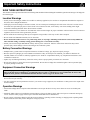 2
2
-
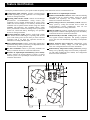 3
3
-
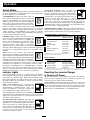 4
4
-
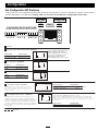 5
5
-
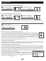 6
6
-
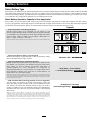 7
7
-
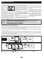 8
8
-
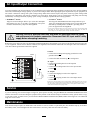 9
9
-
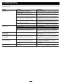 10
10
-
 11
11
-
 12
12
-
 13
13
-
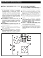 14
14
-
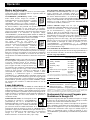 15
15
-
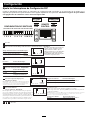 16
16
-
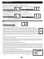 17
17
-
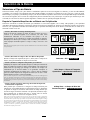 18
18
-
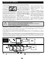 19
19
-
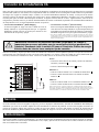 20
20
-
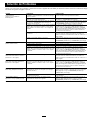 21
21
-
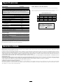 22
22
-
 23
23
-
 24
24
-
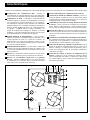 25
25
-
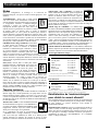 26
26
-
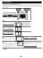 27
27
-
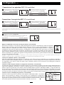 28
28
-
 29
29
-
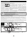 30
30
-
 31
31
-
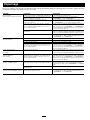 32
32
-
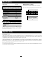 33
33
-
 34
34
-
 35
35
-
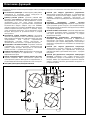 36
36
-
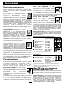 37
37
-
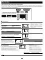 38
38
-
 39
39
-
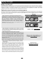 40
40
-
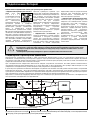 41
41
-
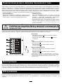 42
42
-
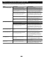 43
43
-
 44
44


Tripp Lite Welding System APSX6048VR Manuel utilisateur
- Taper
- Manuel utilisateur
- Ce manuel convient également à
dans d''autres langues
Documents connexes
-
Tripp Lite PowerVerter APS X 3000W Manuel utilisateur
-
Tripp Lite APSX3024SW Le manuel du propriétaire
-
Tripp Lite RV Series Le manuel du propriétaire
-
-
-
-
-
-
-
Tripp Lite TRIPP-LITE PV1000HF PowerVerter DC-to-AC Inverters Le manuel du propriétaire