La page est en cours de chargement...

Manual No.: 13927003
Date of Release
Movipol-3
Instruction Manual

Movipol-3
Instruction Manual
Table of Contents Page
User’s Guide .............................................................. 1
Reference Guide ...................................................... 16
Quick Reference Guide ............................................ 21
Always state Serial No and Voltage/frequency if you have technical questions or when ordering spare parts.
You will find the Serial No. and Voltage on the type plate of the machine itself. We may also need the Date
and Article No of the manual. This information is found on the front cover.
The following restrictions should be observed, as violation of the restrictions may cause cancellation of Struers
legal obligations:
Instruction Manuals: Struers Instruction Manual may only be used in connection with Struers equipment
covered by the Instruction Manual.
Service Manuals: Struers Service Manual may only be used by a trained technician authorised by Struers.
The Service Manual may only be used in connection with Struers equipment covered by the Service Manual.
Struers assumes no responsibility for errors in the manual text/illustrations. The information in this manual is
subject to changes without notice. The manual may mention accessories or parts not included in the present
version of the equipment.
The contents of this manual is the property of Struers. Reproduction of any part of this manual without the
written permission of Struers is not allowed.
All rights reserved. © Struers 2009.
Struers A/S
Pederstrupvej 84
DK-2750 Ballerup
Denmark
Telephone +45 44 600 800
Fax +45 44 600 801

Movipol-3
Instruction Manual
Movipol-3
Safety Precaution Sheet
To be read carefully
before use
1. The operator must be fully instructed in the use of the apparatus,
according to the User's Guide.
2. The operator must be fully instructed in the use of the electrolytes used
with Movipol-3.
3. Observe the current safety precautions regarding the handling, mixing,
filling and disposal of the electrolyte (see section Safety Precautions).
The Material Safety Data Sheet for each of the Struers electrolytes can
be supplied upon request.
4. Be sure that the actual voltage corresponds to the voltage stated on the
type plate of the apparatus.
5. Check that the apparatus is standing firmly on the support. If the
apparatus is carried or hung by the shoulder strap, check that the strap
is intact and that the buckle is correctly fastened.
6. Always check that the pump motor is working before taking the pencil
out of its holder.
7. Always place the pencil in its holder when it is not used.
8. Do not leave the apparatus unattended when filled with electrolyte.
9. Make sure that the apparatus is safely secured during transportation
and that is does not contain electrolyte.
10. The maximum polishing voltage allowed at the work site must be
observed.
The equipment should only be used for its intended purpose and as detailed in the Instruction Manual.
The equipment is designed for use with consumables supplied by Struers. If subjected to misuse, improper
installation, alteration, neglect, accident or improper repair, Struers will accept no responsibility for damage(s)
to the user or the equipment.
Dismantling of any part of the equipment, during service or repair, should always be performed by a qualified
technician (electromechanical, electronic, mechanical, pneumatic, etc.).

Movipol-3
Instruction Manual
Disposal
Equipment marked with a WEEE symbol contain electrical and
electronic components and must not be disposed of as general
waste.
Please contact your local authorities for information on the correct
method of disposal in accordance with national legislation.

Movipol-3
Instruction Manual
1
User’s Guide
Table of Contents Page
1. Getting Started
Checking the Contents of Packing .................................................... 3
Placing Movipol-3 .............................................................................. 3
Getting Acquainted with Movipol-3 .................................................... 4
Supplying Power ............................................................................... 5
Connecting the Transformer .................................................... 5
Charging the Batteries ...................................................................... 5
Connecting the Pump Motor and Cathode ........................................ 5
Connecting the Anode ....................................................................... 5
External Etching Operations .............................................................. 5
2. Operation
Using the Controls............................................................................. 6
Front Panel Controls ................................................................ 6
Safety Functions ............................................................................... 7
Cut-out of Pump Motor ............................................................. 7
Current Limiter Function of the Polish/Etch Circuit ................... 7
Cut-out of Polish/Etch Circuit ................................................... 7
Cut-out in case of under-voltage .............................................. 7
Mounting the Container ..................................................................... 7
Dismounting the Container ................................................................ 7
Mounting the Pump-Container Unit ................................................... 8
Dismounting the Pump-Container Unit .............................................. 8
Filling Electrolyte into the Container .................................................. 8
Emptying the Container of Electrolyte ............................................... 8
Mounting the Polishing Chamber ...................................................... 8
Starting the Polishing/Etching Process .............................................. 9
Stopping the Polishing/Etching Process ............................................ 9
Cleaning the Container and the Pump ............................................ 11
Voltage Examples ........................................................................... 11
Cast Iron. 3.4% C, 0.29% Si, 0.6% Mn, 0.3% P ..................... 11
Duplex Steel ........................................................................... 11
Commercial Pure Aluminium 99.5% Al ................................... 11
Stainless Steel ....................................................................... 12
Low Carbon Steel 0.1% C ...................................................... 12
High Carbon Steel .................................................................. 12
Titanium Alloys ....................................................................... 12

Movipol-3
Instruction Manual
2
3. Safety precautions
Electricity ......................................................................................... 13
Electrolytes in General .................................................................... 13
Perchloric Acid in Particular ............................................................ 13
Training of Operators ...................................................................... 14
Mixing the Solution .......................................................................... 14
Storage of Perchloric Acid or Solution ............................................. 14
Fire and Explosion Hazards ............................................................ 14
Disposal .......................................................................................... 15
Working with Movipol-3 in the field .................................................. 15
Dangerous Localities .............................................................. 15
Safety Measures .................................................................... 15
Dangerous situations ............................................................. 15

Movipol-3
Instruction Manual
3
1. Getting Started
In the packing box you should find the following parts:
1 Movipol-3 with control unit, pump, pencil
1 Transformer
1 Container for electrolyte
1 Anode wire
1 Anode clamp
1 Magnet
1 Shoulder strap
10 Polishing Chambers
1 Funnel
1 Set of Instruction Manuals
Movipol-3 is a portable apparatus for field electropolishing. If
possible the apparatus should be placed on a stable support. If not it
can be hung by the shoulder trap in a suitable place.
During transportation the apparatus must not contain electrolyte and
should be secured in order not to turn upside down.
Checking the Contents of
Packing
Placing Movipol-3

Movipol-3
Instruction Manual
4
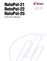
Take a moment to familiarise yourself with the location and names of
the Movipol-3 components.
Charge/pump switch Charge indicator
Start button Voltage indicator for pump motor
Adjusting knob for polishing
voltage Polishing indicator
Etching indicator
Adjusting knob for etching
voltage Socket pump/cathode
Socket anode
Polishing time Socket for external etching
Etching time
Pencil
Ammeter
Getting Acquainted with
Movipol-3

Movipol-3
Instruction Manual
5
Connect the mains cable to the mains.
Connect the 42V multi plug to the left side of Movipol-3.
Switch O/Charge - l/Pump to top position, the batteries of
Movipol-3 are now being charged. When the batteries are fully
charged, the Charge Indicator lights green. If the batteries need
charging the Charge Indicator will light red.
Even though the batteries are factory charged, Struers recommends
the charging of Movipol-3 batteries 1-2 hours before operating the
apparatus.
Connect the multi plug to the socket in the control unit with the
screw cap. Both the electrolyte pump motor and the cathode in
the pencil are now connected to the control unit.
Place the banana plug of the anode wire in the socket, Anode.
The connection to the sample is established with the enclosed
magnet or clamp.
When external etching operations should be carried out, i.e.
when using a cathode connection other than the built-in cathode
in the pencil, the black socket, Output Volt 2-90V DC should be
used as cathode connection.
Supplying Power
IMPORTANT
Check that the mains voltage corresponds to the voltage stated on the type
plate on the side of the machine.
Connecting the Transformer
Charging the Batteries
WARNING
A fully charged set of batteries will self-discharge in 6 months, and a
complete discharging may reduce the lifetime. Therefore the batteries
should be charged at regular intervals.
IMPORTANT
When the transformer is being used Movipol-3 should only be operated
when the Charge Indicator lights green or yellow.
Connecting the Pump Motor
and Cathode
Connecting the Anode
External Etching Operations

Movipol-3
Instruction Manual
6
2. Operation
Name Function
Name Function
O/CHARGE
I/PUMP SWITCH
When switched to O/Charge the
batteries are being charged if
the apparatus is connected to
mains. When switched to l/Pump
the pump motor starts operating.
AMMETER
For reading the amperage
during the polishing/etching
process. The range of 0-2 is
used for polishing. The range of
0-0.2 A is used for etching.
Changing between the ranges is
done automatically when the
timers switch from polishing to
etching.
START BUTTON
Push button for starting the
polishing/etching process.
CHARGE INDICATOR
Indicates the battery charging
level. When connected to 42V
AC possible readings are as
follows:
Battery Charging
Level O/ I/
Charge Pump
Medium charged Yellow Green
Fully charged Green Green
Not Charged Red Red
ADJUSTING KNOB FOR
POLISHING VOLTAGE
Adjusting knob for setting the
voltage for polishing. It can be
set in the range of 10-90 V. The
voltage range of 60-90 volt DC is
marked with a voltage danger
warning.
VOLTAGE INDICATOR
FOR PUMP MOTOR
Indicates whether the pump is
supplied with sufficient voltage:
0: The apparatus is switched off.
Yellow: Pump motor in operation
at sufficient voltage.
Red: Pump motor blocked due
to overload of pump motor or too
low voltage. Electrical circuit
switched off due to overload.
ADJUSTING KNOB FOR
ETCHING VOLTAGE
Adjusting knob for setting the
voltage for etching.
POLISHING
INDICATOR
The Polishing Indicator lights red
when the polishing process is
running and is switched off when
the process is finished.
POLISHING TIME
Adjusting knob for setting the
time of polishing. When set to ∞
the process continues until the
knob is set to zero.
ETCHING INDICATOR
The Etching Indicator lights red
when the etching process is
running and is switched off when
the process is finished.
ETCHING TIME
Adjusting knob for setting the
time of etching. When set to ∞
the process continues until the
knob is set to zero.
SOCKET PUMP/
CATHODE
For connecting the pump motor
and cathode to the control unit.
Using the Controls
Front Panel Controls

Movipol-3
Instruction Manual
7
Name Function
Name Function
SOCKET
ANODE
For connecting the anode wire to
the control unit.
SOCKET
FOR
EXTERNAL
ETCHING
For connecting the cathode
when external etching
operations should be carried
out.
In case of higher load than 1 A the cut-out function is activated. The
Voltage Indicator for Pump Motor will light red. The apparatus can be
restarted when the error has been eliminated.
In case of a voltage range of 70-90 V the current is limited
corresponding to the maximum effect of the transistors (140 VA).
In case of a voltage range of 2-70 V at 2 A the cut-out function is
activated and an alarming signal is heard. When the error has been
corrected the apparatus can be restarted. In case of overload the
circuit is cut out and the Voltage indicator for Pump Motor lights red.
The apparatus can be restarted after cooling when the indicator
lights yellow.
Under-voltage may occur using insufficiently charged batteries. The
cut out function for under-voltage will disconnect the process and an
alarm signal is heard.
Place the pump in the container.
Press down the black knobs and turn them until the markings
turn towards the pump.
Check that the container is firmly locked.
Press the two black knobs down and turn them so that the
markings turn away from the pump, a click is heard and the
pump is released from the container.
Safety Functions
Cut-out of Pump Motor
Current Limiter Function of the
Polish/Etch Circuit
Cut-out of Polish/Etch Circuit
Cut-out in case of under-voltage
Mounting the Container
Dismounting the Container

Movipol-3
Instruction Manual
8
Lower the pump-container unit into the cabinet.
Press the unit down until a click is heard. The pump-container
unit is now locked in the cabinet.
Press the two black locks to the sides from the pump in direction
of the cabinet wall, a click is heard and the pump-container unit
is dismounted and can be removed from the cabinet.
Before filling electrolyte into the container, the section, Safety
Precautions should be carefully observed.
Remove the pump and container from the cabinet.
Remove the pump from the electrolyte container.
Pour the electrolyte into the electrolyte container. The level must
be between the minimum (350 ml) and maximum (750 ml)
marks.
Mount the container on the pump and mount the unit in the
cabinet of Movipol-3.
Before emptying the container of electrolyte, the section, Safety
Precautions should be carefully observed.
Remove the pump-container unit from the cabinet and remove
the container.
If the electrolyte is to be used again pour the electrolyte carefully
back into the electrolyte bottle. Use the funnel supplied with the
apparatus.
If the electrolyte is not to be used again it should be filled into a
container suitable for disposal. Please observe the local
regulations and instructions for disposal.
Press the polishing chamber onto the pencil until it fits tightly.
A polishing chamber has a limited lifetime as the plastic hardens
because of contact with the electrolyte. The chamber should be
renewed regularly.
Mounting the Pump-Container
Unit
Dismounting the Pump-
Container Unit
Filling Electrolyte into the
Container
Emptying the Container of
Electrolyte
IMPORTANT
Funnel, gloves, ventilation as well as all other prescribed equipment must be
used during filling/emptying.
Mounting the Polishing
Chamber

Movipol-3
Instruction Manual
9
Make sure that the correct type and amount of electrolyte has
been filled in the electrolyte container.
Connect the anode to the sample by means of the clamp or
magnet supplied with the apparatus.
Set the polishing voltage and polishing time.
Set the etching voltage and etching time.
Activate the pump motor by switching O/Charge - l/Pump to
bottom position.
Take the pencil from the pencil holder and place it on the spot
which is to be prepared.
Press the pencil against the surface ensuring that the polishing
chamber is in total contact with the surface.
Keep the pencil perpendicular (at a angle of 90°) to the surface.
The electrolyte will now begin to circulate.
Press the button START . A "sensor circuit" records whether
there is electric connection from the cathode in the pencil
through the electrolyte to the anode.
If the electric circuit is closed the timer starts the process.
Read the ammeter to check if the correct amperage has been
obtained.
When both the Polishing and Etching Indicators are switched off
the process has been completed and the pencil should be
placed in the pencil holder.
When the pencil has been placed in the holder, switch off the
pump motor by switching the O/charge - l/Pump to O/Charge.
Clean the polished spot with water/alcohol and dry carefully.
The polishing/etching process can be stopped at any time during
operation by setting the adjusting knob for polishing/etching time
to zero.
Starting the Polishing/Etching
Process
IMPORTANT
Take care that no air is drawn around the periphery of the polishing
chamber.
IMPORTANT
Only press the start button when the noise from the pump indicates that the
flow through the pencil is constant.
Stopping the Polishing/Etching
Process

Movipol-3
Instruction Manual
10
After polishing with one electrolyte or after mechanical polishing, the
sample can be etched using a different electrolyte and the external
etching connection. (External etching accessory required)
Connect the anode to the sample using the clamp or magnet
supplied with Movipol-3.
Connect the tongs for external etching to the black socket on the
Movipol-3.
Set the etching voltage and etching time.
Pick up a ball of cotton wool with the tongs.
Dip the cotton wool ball in a suitable electrolyte (e.g. 10% oxalic
acid for stainless steel).
Start the pump and then the polishing/etching process.
Swab the specimen surface with the cotton wool, and observe
the movement on the Ammeter.
Clean the polished spot with water/alcohol and dry carefully.
External Etching

Movipol-3
Instruction Manual
11
The electrolyte container and the pump system must be cleaned with
water after use.
Empty the container of electrolyte.
Fill the container with water and start the pump by switching
O/Charge - l/Pump to bottom position to circulate water from the
electrolyte container through the pump system.
Due to graphite inclusions, electrolytic polishing is not ideal, but it is
satisfactory for "testing on the spot". The metallic structure develops
excellently and only the graphite appearance will be less successful.
Due to the softness of the graphite this may be helped by rubbing
the polished surface with a piece of wet cotton wool, perhaps with
AP-Alumina Suspension FF.
Pregrinding with Transpol Up to grit 400
Electrolyte AC-2
Polishing voltage 40V
Polishing current 0.5A
Polishing time 15 sec
Pregrinding with Transpol Up to grit 400
Electrolyte A-2
Polishing
Voltage 35V
Current 0.7A
Time 15 sec
Etching
Voltage 8V
Current 0.2A
Time 12 sec
Pregrinding with Transpol Up to grit 400
Electrolyte A-2
Polishing voltage 85V
Polishing current 0.3A
Polishing time 20 sec
Cleaning the Container and the
Pump
Voltage Examples
Cast Iron. 3.4% C, 0.29%
Si, 0.6% Mn, 0.3% P
Duplex Steel
Commercial Pure Aluminium
99.5% Al

Movipol-3
Instruction Manual
12
Pregrinding with Transpol Up to grit 400
Electrolyte E-5
Polishing voltage 80V
Polishing current 0.6A
Polishing time 10 sec
External etch in 10% Oxalic acid or 10% (NH)2S2O3
Pregrinding with Transpol Up to grit 400
Electrolyte A-2
Polishing
Voltage 60V
Current 0.8A
Time 10 sec
Etching
Voltage 5V
Current 0.18A
Time 5 sec
Pregrinding with Transpol Up to grit 220
Electrolyte A-2
Polishing
Voltage 60V
Current 1.0A
Time 15 sec
Etching
Voltage 3-6V
Current 0.013A
Time 3 sec
Pregrinding with Transpol Up to grit 220
Electrolyte A-3
Polishing voltage 50V
Polishing current 1.0A
Polishing time 15 sec
Stainless Steel
Low Carbon Steel 0.1% C
High Carbon Steel
Titanium Alloys

Movipol-3
Instruction Manual
13
3. Safety precautions
In some working areas a maximum safety voltage is specified. Such
a maximum range would typically be 42V AC (60 DC). Movipol-3 is
used with a 42V AC transformer through a 54V DC re-chargeable
battery set. Movipol-3 can be used according to these restrictions.
Alternatively Movipol-3 may work on batteries only.
When using electrolytes all necessary safety measures should be
taken. Apart from the safety precautions listed in the following, a
material Safety Data Sheet for each of the electrolytes delivered by
Struers can be supplied upon request.
It is essential that the user(s) is/are fully instructed in the work
procedure of these electrolytes.
Movipol-3 is designed for use with electrolytes recommended by
Struers. Other electrolytes, e.g. electrolytes containing strong
bases or acids, may harm the construction or endanger the
safety of the user.
NOTE that many electrolytes contain alcohol or other
inflammable solvents. Make sure that all safety
precautions are followed when using such electrolytes.
When cleaning the apparatus after use, make sure that no
electrolyte is allowed to dry and/or crystallise inside the
apparatus or on the polished material.
It is essential that the user is fully trained in the use of Movipol-3
and electrolytes involved.
Electrolytes from Struers with the prefix A consist of approx. 1 l stock
solution to which 15 to 90 ml perchloric acid (60%) should be added.
Before mixing the perchloric acid to the stock solution it is of great
importance that the following safety precautions are carefully
observed. Furthermore a Material Safety Data Sheet for the
perchloric acid in question can be supplied upon request.
Electricity
WARNING
The polishing circuit may generate voltages up to 90V DC. The Adjusting
knob for Polishing Volt indicates the critical range from 60 to 90V in yellow.
Electrolytes in General
Perchloric Acid in Particular

Movipol-3
Instruction Manual
14
All personnel involved in the mixing, use, storage, transportation,
and disposal of the electrolytes or its components, should be
thoroughly trained in the precautions for handling perchloric acid.
Great importance must be attached to precautions against
inhalation of vapours of the solution or its components, against
skin contact, mixing and overheating, and concerning storage
and disposal methods.
Place the solvent/water mixture in a water bath with temperature
control. Carefully add the perchloric acid to the solvent/water
mixture, stir continuously.
The mixing must take place in a ventilated chemical fume hood
designed for perchloric acid use.
The operator(s) must use the listed protective clothing or
devices: full face shield or splash goggles, rubber gloves and lab
coat or coveralls.
Avoid the use of any combustible or carbonaceous containers,
reaction vessels, spill pans, storage shelves, or materials of this
type when dealing with the acid.
Do not permit any acid to crystallise on bottle necks, caps, or
anywhere else.
Store in secure, cool, and ventilated area with metal, glass, or
ceramic spill catch pan.
Store away from other chemicals, combustible and organic
materials.
Do not, under any circumstances, permit solutions to dry out.
60% perchloric acid is a strongly corrosive and oxidising product.
Heating may cause an explosion and contact with combustible
material may cause fire.
Fire fighting should be done from a protected location.
Extinguish with water spray only. Do not use dry chemicals or
carbon dioxide.
Do not produce anhydrous perchloric acid, either from its salts or
from aqueous solutions, e.g. by heating with high boiling acids or
dehydrating agents, such as sulphuric acid or phosphorous
pentoxide. In addition to spontaneous explosion, the anhydrous
acid explodes instantaneously on contact with oxidizable organic
materials.
The use or storage of perchloric acid should be limited to
quantities less than 500 g per hood.
Training of Operators
Mixing the Solution
Storage of Perchloric Acid or
Solution
Fire and Explosion Hazards

Movipol-3
Instruction Manual
15
Follow local regulations for disposal of spillage and waste.
Dilution and/or neutralisation are the normally recommended
methods of disposal of the electrolyte.
Certain safety measures must be taken when working with Movipol-3
in the field as some working locations can be dangerous. This is the
case when working in:
Closed containers, e.g. boilers, tanks and fractionating columns.
Narrow areas such as shafts, pits, pipes and tunnels.
Working in these above mentioned locations can be dangerous as
poisonous substances can be accumulated and as there can be too
little oxygen in the air.
Consequently it is recommended that tanks or other narrow areas
are not opened or entered without written permission.
Necessary preparations and safety precautions should be mentioned
in the permission and it must be issued by the manager in charge of
safety for the actual process line or plant.
No working process should begin without this permission. The safety
precautions and work processes stated for the place of work should
be followed. In case of doubt regarding the contents of the
authorisation, the issuer should be consulted.
Dangerous situations can occur when working in locations with
choking or poisonous gases. In order to make sure that the air can
be breathed without risk it must be analysed. Electric insulation
defects may also involve a safety risk.
However, safe working procedure may be carried out if adequate
safety precautions are taken before and during the work process.
Disposal
Working with Movipol-3
in the field
Dangerous Localities
Safety Measures
Dangerous situations

Movipol-3
Instruction Manual
16
Reference Guide
Table of Contents Page
1. Consumables and Accessories
Accessories for Movipol-3 ............................................................... 17
Supplementary Equipment .............................................................. 17
2. Trouble-shooting
Electrolyte ....................................................................................... 18
Flow ................................................................................................ 18
Pencil and Cathode ......................................................................... 18
Polishing Chamber .......................................................................... 18
Power Supply .................................................................................. 18
3. Maintenance
Pump and Electrolyte Container ...................................................... 19
Every day ............................................................................... 19
Cabinet ........................................................................................... 19
Every day ............................................................................... 19
Every week ............................................................................ 19
Once a year ........................................................................... 19
Exchange of Batteries ..................................................................... 19
4. Technical Data ..................................................................... 20
1/116