
PURE SINE WAVE INVERTER
SR-1600 PLUS Shelf User’s Manual
Telecom / Datacom
ONDULEURS PUR SINUS
Applications Télécom / Datacom
FR
[Page 14]
EN
[Page 1]


Legal Provisions
Copyrights 2016 COTEK Electronic IND. CO. All Rights Reserved.
Any part of this document may not be reproduced in any form for any purpose without the prior
written permission of COTEK Electronic IND. CO. For the conditions of the permission to use
this manual for publication, contact COTEK Electronic IND. CO., LTD. In all related COTEK
product activities, Neither COTEK Electronic IND. CO., LTD. nor its distributors or dealers be
liable to anyone for indirect, incidental, or consequential damages under any circumstances.
Specifications are subject to change without notice. Every attempt has been made to make this
document complete, accurate and up-to-date. COTEK Electronic IND. CO., LTD reserve the
right to make changes without notice and shall not be responsible for any damages, including
indirect, incidental or consequential damages, caused by reliance on the material presented,
including, but not limited to, omissions, typographical errors, arithmetical errors or listing errors
in the content material. All trademarks are recognized even if these are not marked separately.
Missing designations do not mean that a product or brand is not a registered trademark.


Table of Content
1. SAFETY INSTRUCTIONS 1
1-1. General Safety Precautions 1
1-2. Other Safety Notes 2
2. MECHANICAL DRAWINGS (19” 2U) 3
3. INTRODUCTION AND INSTALLATION 4
3-1. Installation 5
3-2. Green Terminal Introduction 5
3-2-1. Jumper A & B ......................................................................... 6
3-2-2. AC Input / Output Terminal .................................................... 7
3-2-3. Dry contact and remote ......................................................... 7
3-3. Parallel Connection 12
3-3-1. Multi-shelves Installation ..................................................... 12
3-3-2. Parallel Connection with Jumper Setting............................. 12
4. WARRANTY 13

1
EN
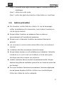
1. Safety Instructions
1-1. General Safety Precautions
Warning! Before using the Inverter, read the safety instructions.
Do not expose the inverter to rain, snow, spray or dust. To reduce
the risk of fire hazard, do not cover or obstruct the ventilation
openings and do not install the inverter in a zero-clearance
compartment.
To avoid the risk of fire and electric shock, make sure that the
existing wiring is in good electrical condition, and the wire size is not
undersized.
This equipment contains components which can produce arcs or
sparks. To prevent fire or explosion do not install in compartments
containing batteries or flammable materials or in locations which
require ignition protected equipment. This includes any space
containing gasoline-powered machinery, fuel tanks, or joints, fittings,
or other connection between components of the fuel system.
Depending on the user scenario, the AC output of the inverter may
require user installed breaker or fuse. In AC output hardwire
application, AC socket will not be provided. The inverter incorporates
standard AC short circuit protection.
The following precautions should be taken when working on the
inverter:
Step 1 Remove watches, rings, or other metal objects
Step 2 Use tools with insulated handles
Step 3 Wear rubber gloves and boots

2
EN
Warning! For the terminals on the backplane including AC,
battery, output, signal, please do not change or rework the
terminal wiring unless you are a qualified engineer
1-2. Other Safety Notes
Upon receipt, examine the carton box for damage. Notify the carrier
immediately, before opening, if damage is evident.
Do not operate near water or in excessive humidity.
The DC side connections should be firm and tight.
Grounding:Reliable grounding should be maintained.
Do not drop a metal tool on the battery. The resulting spark or
short-circuit on the battery or on the other electrical part may cause
an explosion.
Install the inverter in a well-ventilated area. Do not block the front air
vents, or the rear air exhausts of the unit.
Wiring:Adequate input power must be supplied to the inverter for
proper use; correct wiring sizes must be ensured.
Mount the inverter such that the fan axis is horizontal.
Do not operate the inverter close to combustible gas or open fire.
Do not operate appliances that may feed power back into the
inverter.
Temperature:The inverter should be operated in an ambient
temperature range of -25℃ to 40 ℃ otherwise the output efficiency
may be affected. Air flow to the inverter must not be blocked.

3
EN
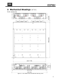
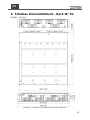
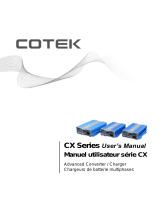
2. Mechanical Drawings (19” 2U)
Unit: mm[inch]
Figure 1. SR-1600 PLUS mechanical drawing-rack

4
EN
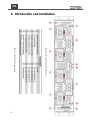
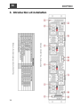
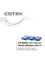
3. Introduction and Installation
Figure
2. SR-1600 PLUS shelf rear panel
view
Table
1. SR-1600 PLUS description

5
EN
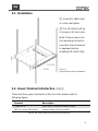
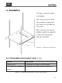
3-1. Installation
① Insert SR-1600 shelf
in to the shelf plate.
② Fix SR-1600 shelf by
4 screws at its front side.
Note: Please make sure
the mounting bracket of
your rack mount deceive
is equipped before
installing SR-1600 shelf.
Figure 3.
SR-1600 PLUS shelf installation
3-2. Green Terminal Introduction ③⑧⑨
There are three green terminals at the rear side, please refer to
following figure:
Terminal
Description
Jumper A & B
Single shelf / Parallel connection setting
CN3 Dry contact and remote
Remote setting, and dry contacts
Table 2. SR-1600 PLUS green terminal introduction

6
EN
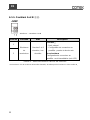
3-2-1. Jumper A & B ③⑧
Figure 4. Jumper A & B
Pin
Function
Wiring
Status description
1
Terminal
Resistor
Pin#1 and
Pin#2
short/open
Short:
1. Signal shelf setting
*
Note
2. Parallel connection setting at first and last shelf
(terminal shelf)
Open:
Parallel connection:non-terminal shelf (Refer to
3-2-2.)
2
Table 3. SR-1600 PLUS jumper A & B status description
*
Note:Jumper A pin1 & pin2 must be shorted and Jumper B pin1 & pin2 must
be shorted.

7
EN
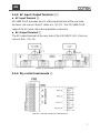
3-2-2. AC Input / Output Terminal ④⑦
AC Input Terminal ④
SR-1600 PLUS provides the AC utility input terminal at the rear side,
and user can connect the AC cable at L / N / FG. The SR-1600 PLUS
support the AC input side internal parallel connection.
AC Output Terminal ⑦
The AC output terminal at the rear side of the SR-1600 PLUS. User can
connect the L / N / FG.
Figure 5. AC terminal connection
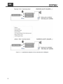
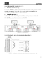
3-2-3. Dry contact and remote ⑨
Figure 6. CN3 dry contact pin assignment

8
EN
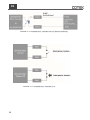
Figure 6-1. Application diagram of dry contact pin3~5(Major)

9
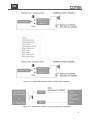
EN
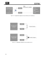
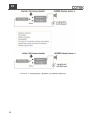
Figure 6-2. Application diagram of dry contact pin6~8(Minor)
Figure 6-3. Application diagram of dry contact pin12~13(Major)

10
EN
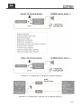
Figure 6-4. Application diagram of dry contact pin14~13(Minor)
Figure 6-5. Application diagram of dry contact pin1~2

11
EN
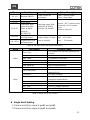
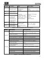
Pin
Function
Wiring
Status Description
Pin 1~2
Remote ON/OFF
Pin#1 and pin #2
short/open
Open:Normal output
Short:Stop output
Pin 3~5
Major alarm
Switching power 60W
Rating 2A at 30VDC
wire size 20~24AWG
Normal:N.C-Common short
Abnormal:N.O-Common
short
(Refer to Figure 9.)
Pin 6~8
Minor alarm
Pin 9~11
Selectable extra
alarm to go with
Major or minor
alarm by
RS485/LCM
Pin12~13
Digital signal input
for Major alarm
Signal voltage:5V wire
size 20~24AWG
High:+5V Action
Low: 0V Normal
Pin 13~14
Digital signal input
for Minor alarm
Table 4. SR-1600 PLUS CN3 status description
Alarm
Description
Possible Cause
Major
Over Load
The system over the rated capacity(OLA
>15sec)
Module Fault
Parallel Fault or Module Fault
Over Temp.
Temperature is too high
DC abnormal & Grid abnormal
Both sources fail (AC&DC source abnormal)
Major relay on
Pin 12~13 Action
CAN signal fail
Not connected properly
Minor
Grid abnormal
AC source failure
Over Load Alarm
The system over the rated
capacity(OLA )
Fan failure
Fan does not work
Redundancy Fault
Remove the redundancy module or
redundant module failure
Minor relay on
Pin 13~14 Action
BAT. Low
Under DC voltage protection
BAT. High
Over DC voltage protection
BAT. Low Alarm
Under DC voltage Alarm
BAT. High Alarm
Over DC voltage Alarm
Table 5. Alarm list for dry contact
Single Shelf Setting
1. Please short the Jumper A pin#1 and pin#2.
2. Please short the Jumper B pin#1 and pin#2.

12
EN
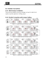
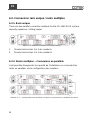
3-3. Parallel Connection
3-3-1. Multi-shelves Installation
There are two parallel connection methods for the SR-1600 PLUS
system capacity expansion: Setting jumper
3-3-2. Parallel Connection with Jumper Setting
Figure 7-1. Parallel connection via jumper setting
Figure 7-2. Parallel connection via jumper setting
Figure 7-3. Parallel connection via jumper setting

13
EN
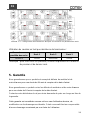
Green terminal JUMP connection:
Parallel connect
Unit 1
Unit 2
Unit 3
JUMP
Connected
Not connected
Connected
※ Take 3 units for example, only the first and the last unit need to
connect jumper.
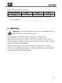
4. Warranty
Warning! Do not open or disassemble the Inverter. Attempting to do so
may cause risk of electrical shock or fire.
We guarantee this product against defects in materials and
workmanship for a period of 24 months from the date of purchase. In
case you need to repair or replace any defective power inverters, please
contact COTEK local distributor.
This warranty will be considered void if the unit has been misused,
altered, or accidentally damaged. COTEK is not liable for anything that
occurs as a result of the user’s fault.

14
FR
Dispositions légales
Copyrights 2016 COTEK Electronic IND. CO. tous droits réservés.
Aucune partie de ce document ne peut être reproduite, quelle qu’en soit la manière et quel
qu’en soit le but, sans autorisation préalable écrite de COTEK Electronic IND. CO. Pour obtenir
l’autorisation de publier ce manuel, adressez-vous directement à COTEK Electronic IND. CO.,
LTD. Pour l’ensemble des activités COTEK, ni COTEK Electronic IND. CO., LTD. ni ses
distributeurs ou revendeurs ne sauraient être tenus responsables, d’aucune manière, de tout
dommage direct, indirect ou accessoire. Les caractéristiques peuvent être modifiées sans
notification préalable.
Tout a été mis en oeuvre pour que ce document soit complet, précis et à jour. COTEK
Electronic IND. CO., LTD. se réserve le droit d’apporter des modifications sans notification et
ne saurait être tenu responsable de tout dommage direct, indirect ou accessoire causé par
l’utilisation de ce contenu, y compris mais non limité à des omissions, des coquilles, des
erreurs de calcul ou de description. Toutes les marques sont protégées même sans indication
spécifique. L’absence de logo ne signifie pas que le produit ou la marque ne sont pas protégés.

15
FR
Table des matières
1. CONSIGNES DE SÉCURITÉ 16
1-1. Consignes de sécurité 16
1-2. Autres précaution 17
2. SCHÉMAS D'ENCOMBREMENT – RACK 19'' 2U 19
3. INTRODUCTION ET INSTALLATION 20
4. INSTALLATION 21
4-1. Présentation des borniers verts – 3 8 9 21
4-4-1. Cavaliers A et B – 3 8 .......................................................... 22
4-4-2. Entrée CA / Sortie CA – 4 7 ................................................. 23
4-4-3. Contacts secs et commande déportée – 9 .......................... 23
4-2. Connexions rack unique / racks multiples 28
4-2-1. Rack unique ......................................................................... 28
4-2-2. Racks multiples – Connexions en parallèle......................... 28
5. GARANTIE 29
La page charge ...
La page charge ...
La page charge ...
La page charge ...
La page charge ...
La page charge ...
La page charge ...
La page charge ...
La page charge ...
La page charge ...
La page charge ...
La page charge ...
La page charge ...
La page charge ...
La page charge ...
-
 1
1
-
 2
2
-
 3
3
-
 4
4
-
 5
5
-
 6
6
-
 7
7
-
 8
8
-
 9
9
-
 10
10
-
 11
11
-
 12
12
-
 13
13
-
 14
14
-
 15
15
-
 16
16
-
 17
17
-
 18
18
-
 19
19
-
 20
20
-
 21
21
-
 22
22
-
 23
23
-
 24
24
-
 25
25
-
 26
26
-
 27
27
-
 28
28
-
 29
29
-
 30
30
-
 31
31
-
 32
32
-
 33
33
-
 34
34
-
 35
35


Cotek SR 1600 Rack Manuel utilisateur
- Taper
- Manuel utilisateur
- Ce manuel convient également à
dans d''autres langues
- English: Cotek SR 1600 Rack User manual
Documents connexes
-
 Cotek SR-1600 PLUS series Manuel utilisateur
-
 Cotek SR-1600 PLUS series Manuel utilisateur
-
 Cotek SD1500, SD2500, SD3500 Manuel utilisateur
-
 Cotek SE200, SE350, SE400 Manuel utilisateur
-
 Cotek CR-6 Manuel utilisateur
-
 Cotek CR-20C Manuel utilisateur
-
 Cotek CX series Manuel utilisateur
-
 Cotek Sc Series Manuel utilisateur
-
 Cotek CX series Manuel utilisateur


