RIDGID 10973 Manuel utilisateur
- Catégorie
- Outils électroportatifs
- Taper
- Manuel utilisateur

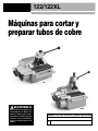
Copper Cutting and Prep
Machines
• Français – 15
• Castellano – pág. 31
122/122XLManual

999-998-069.10_REV. C
ii
122/122XL Copper Cutting and Prep Machines
Table of Contents
Recording Form for Machine Serial Number..............................................................................................................1
Safety Symbols..............................................................................................................................................................2
General Power Tool Safety Warnings
Work Area Safety........................................................................................................................................................2
Electrical Safety ..........................................................................................................................................................2
Personal Safety ..........................................................................................................................................................3
Power Tool Use and Care ..........................................................................................................................................3
Service ........................................................................................................................................................................3
Specific Safety Information
Copper Cutting and Prep Machines Safety ................................................................................................................4
Description, Specifications and Standard Equipment
Description ..................................................................................................................................................................4
Standard Equipment ..................................................................................................................................................4
Specifications..............................................................................................................................................................5
Icons ..........................................................................................................................................................................6
Tool Assembly
Fitting Brushes and Holder ........................................................................................................................................6
O. D. Deburring Disk ..................................................................................................................................................6
Pre-Operation Inspection ............................................................................................................................................6
Machine and Work Area Set-Up ..................................................................................................................................7
Using Foot Switch (120V Only) ..................................................................................................................................8
Operating Instructions
Cutting Tubes..............................................................................................................................................................9
Cleaning/Deburring O.D. of Tube ............................................................................................................................10
Reaming I.D. of Tube................................................................................................................................................10
Cleaning Inside of Fittings ........................................................................................................................................10
Maintenance Instructions
Cleaning....................................................................................................................................................................11
Lubrication ................................................................................................................................................................11
Adjusting Rack Tension ............................................................................................................................................11
Cutter Wheel Replacement ......................................................................................................................................11
O.D. Brush Replacement ..........................................................................................................................................11
Reamer Blade Replacement ....................................................................................................................................11
Motor Thermal Overload ..........................................................................................................................................12
Accessories ................................................................................................................................................................12
Storage ........................................................................................................................................................................12
Service and Repair......................................................................................................................................................12
Disposal ......................................................................................................................................................................13
Troubleshooting..........................................................................................................................................................13
EC Declaration of Conformity ..........................................................................................................Inside Back Cover
Lifetime Warranty ........................................................................................................................................Back Cover
*Original Instructions - English

122/122XL Copper Cutting and Prep machines
Record Serial Number below and retain product serial number which is located on nameplate.
Serial
No.
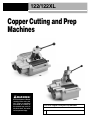
Copper Cutting and Prep
Machines
122/122XL
WARNING!
Read this Operator’s Manual
carefully before using this
tool. Failure to understand
and follow the contents of
this manual may result in
electrical shock, fire and/or
serious personal injury.
122
122XL

999-998-069.10_REV. C
2
122/122XL Copper Cutting and Prep Machines
General Power Tool Safety
Warnings*
WARNING
Read all safety warnings, instructions, illustrations
and specifications provided with this power tool.
Failure to follow all instructions listed below may
result in electric shock, fire and/or serious injury.
SAVE ALL WARNINGS AND INSTRUCTIONS
FOR FUTURE REFERENCE!
The term "power tool" in the warnings refers to your
mains-operated (corded) power tool or battery-operated
(cordless) power tool.
Work Area Safety
• Keep your work area clean and well lit. Cluttered or
dark areas invite accidents.
• Do not operate power tools in explosive atmo-
spheres, such as in the presence of flam mable
liquids, gases, or dust. Power tools create sparks
which may ignite the dust or fumes.
• Keep children and bystanders away while operat-
ing a power tool. Distractions can cause you to lose
control.
Electrical Safety
• Power tool plugs must match the outlet. Never
modify the plug in any way. Do not use any adap -
ter plugs with earthed (grounded) power tools.
Un modified plugs and matching outlets will reduce
risk of electric shock.
• Avoid body contact with earthed or grounded sur-
faces such as pipes, radiators, ranges and refrig-
erators. There is an increased risk of electrical shock
if your body is earthed or grounded.
• Do not expose power tools to rain or wet condi-
tions. Water entering a power tool will increase the risk
of electrical shock.
• Do not abuse the cord. Never use the cord for
carrying, pulling or unplugging the power tool.
Keep cord away from heat, oil, sharp edges or
Safety Symbols
In this operator’s manual and on the product, safety symbols and signal words are used to communicate important safe-
ty information. This section is provided to improve understanding of these signal words and symbols.
DANGER
This is the safety alert symbol. It is used to alert you to potential personal injury hazards. Obey all safety messages that follow this
symbol to avoid possible injury or death.
DANGER indicates a hazardous situation which, if not avoided, will result in death or serious injury.
WARNING
WARNING indicates a hazardous situation which, if not avoided, could result in death or serious injury.
CAUTION
CAUTION indicates a hazardous situation which, if not avoided, could result in minor or moderate injury.
NOTICE indicates information that relates to the protection of property.
This symbol means read the operator’s manual carefully before using the equipment. The operator’s manual contains
important information on the safe and proper operation of the equipment.
This symbol means always wear safety glasses with side shields or goggles when handling or using this equipment to reduce
the risk of eye injury.
This symbol indicates the risk of hands, fingers or other body parts being caught or wrapped in rollers or other moving parts
This symbol indicates the risk of hands, fingers or other body parts being cut by the rotating reamer or wire brush or other mov-
ing parts
NOTICE
This symbol indicates the risk of machine tipping, causing striking or crushing injuries.
This symbol means do not wear gloves while operating this machine to reduce the risk of entanglement.
This symbol indicates the risk of electrical shock.
* The text used in the General Power Tool Safety Warnings section of this manual is verbatim, as required, from the applicable EN 62841-1 standard. This section con-
tains general safety practices for many different types of power tools. Not every precaution applies to every tool, and some do not apply to this tool.

999-998-069.10_REV. C
3
moving parts. Damaged or entangled cords increase
the risk of electric shock.
• When operating a power tool outdoors, use an
extension cord suitable for outdoor use. Use of a
cord suitable for outdoor use reduces the risk of elec-
tric shock.
• If operating a power tool in a damp location is
unavoidable, use a ground fault circuit interrupter
(GFCI) protected supply. Use of a GFCI reduces
the risk of electric shock.
Personal Safety
• Stay alert, watch what you are doing and use com-
mon sense when operating a power tool. Do not
use a power tool while you are tired or under the
influence of drugs, alcohol, or medication. A mo -
ment of inattention while operating power tools may
result in serious personal injury.
• Use personal protective equipment. Always wear
eye protection. Protective equipment such as dust
mask, non-skid safety shoes, hard hat, or hearing
protection used for appropriate conditions will reduce
personal injuries.
• Prevent unintentional starting. Ensure the switch
is in the OFF-position before connecting to power
source and/or battery pack, picking up or carrying
the tool. Carrying power tools with your finger on the
switch or energizing power tools that have the switch
ON invites accidents.
• Remove any adjusting key or wrench before turn-
ing the power tool ON. A wrench or a key left attached
to a rotating part of the power tool may result in per-
sonal injury.
• Do not overreach. Keep proper footing and bal-
ance at all times. This enables better control of the
power tool in unexpected situations.
• Dress properly. Do not wear loose clothing or
jewel ry. Keep your hair, clothing, and gloves away
from moving parts. Loose clothes, jewelry, or long
hair can be caught in moving parts.
• If devices are provided for the connection of dust
extraction and collection facilities, ensure these are
connected and properly used. Use of dust collection
can reduce dust-related hazards.
• Do not let familiarity gained from frequent use of
tools allow you to become complacent and ignore
tool safety principles. A careless action can cause
severe injury within a fraction of a second.
122/122XL Copper Cutting and Prep Machines
Power Tool Use and Care
• Do not force power tool. Use the correct power tool
for your application. The correct power tool will do the
job better and safer at the rate for which it is designed.
• Do not use power tool if the switch does not turn it
ON and OFF. Any power tool that cannot be con-
trolled with the switch is dangerous and must be
repaired.
• Disconnect the plug from the power source and/or
remove the battery pack, if detachable, from the
power tool before making any adjustments, chang-
ing accessories, or storing power tools. Such pre-
ventive safety measures reduce the risk of starting
the power tool accidentally.
• Store idle power tools out of the reach of children
and do not allow persons unfamiliar with the pow -
er tool or these instructions to operate the power
tool. Power tools are dangerous in the hands of
untrained users.
• Maintain power tools and accessories. Check for
misalignment or binding of moving parts, breakage
of parts and any other condition that may affect the
power tool’s op er ation. If damaged, have the power
tool repaired before use. Many accidents are caused
by poorly maintained power tools.
• Keep cutting tools sharp and clean. Properly main-
tained cutting tools with sharp cutting edges are less
likely to bind and are easier to control.
• Use the power tool, accessories and tool bits etc.
in accordance with these instructions, taking into
account the working conditions and the work to be
performed. Use of the power tool for operations dif-
ferent from those intended could result in a hazardous
situation.
• Keep handles and grasping surfaces dry, clean
and free from oil and grease. Slippery handles and
grasping surfaces do not allow for safe handling and
control of the tool in unexpected situations.
Service
• Have your power tool serviced by a qualified repair
person using only identical replacement parts.
This will ensure that the safety of the power tool is
maintained.
Specific Safety Information
WARNING
This section contains important safety information
that is specific to this tool.

Description, Specifications and
Standard Equipment
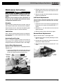
Description
The RIDGID
®
Model 122 and 122XL Copper Cutting and
Prep Machines are designed to cut, clean and deburr cop-
per tubing and fittings (Types K, L and M). These can also
be used to cut and deburr stainless steel tubing with a
maximum wall thickness of .065" (1.65 mm) with a sepa-
rate cutter wheel.
Cutting is performed by turning the tubing with motor-driv-
en rollers while a cutter wheel is manually actuated by a
rack and pinion. An adjustable cutting handle accommo-
dates different diameter tubes and a scale is included for
tube measurement. Reamer removes burrs from the inside
of the tubing while the brush cleans the external surface in
preparation for joining. The machine can also clean the
inside of fittings using individually sized brushes that are
attached to the quick-change adapter. Deburring disk
cleans burrs from the outside surface of the tubing.
The RIDGID
®
Model 122 and 122XL Copper Cutting and
Prep Machines are not designed for use with pipe.
Standard Equipment
The 122 and 122XL Copper Cutting and Prep Machines
come with the following items:
• O. D. Cleaning Brush
• Cone Reamer
• O. D. Deburring Disk (122XL Only)
• Fitting Brush Storage Kit (122 Only)
• Operator’s Manual Pack
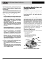
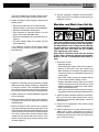
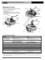
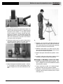
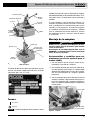
Figure 1A – 122 Copper Cutting and Prep Machine
Read these precautions carefully before using the
122 and 122XL Copper Cutting and Prep Machines
to reduce the risk of electrical shock or serious
personal injury.
SAVE THESE INSTRUCTIONS!
Keep this manual with machine for use by the operator.
Copper Cutting and Prep Machines
Safety
• Do not wear gloves or loose clothing. Keep sleeves
and jackets buttoned. Clothing can be caught in
rotating rollers or tools and cause crushing injuries.
• Secure machine to stable bench or stand. Properly
support the tubes. This reduces the risk of falling
tube, tipping and serious injury.
• Keep fingers and hands away from the rotating
rollers, reamer, wire brushes, deburring disk and
tube. This reduces the risk of entanglement and cut-
ting injuries.
• Do not cut visibly bent tubing or tubing with fit-
tings attached. Reduces the risk of excessive vibra-
tion and loss of control of the machine and/or tubing.
• Only use the machines to cut, clean and deburr
copper or stainless steel tubing as directed in
this manual. Do not use for other purposes or modi-
fy. Other uses or modifying this machine for other
applications may increase the risk of serious injury.
• Read and understand the instructions and warn-
ings for all equipment and material being used
before operating the machines. Failure to follow all
instructions and warnings may result in property dam-
age or serious personal injury.
If you have any question concerning this RIDGID
®
product:
– Contact your local RIDGID distributor.
– Visit RIDGID.com to find your local RIDGID contact
point.
– Contact Ridge Tool Technical Service Department at
Canada call (800) 519-3456.
999-998-069.10_REV. C
4
122/122XL Copper Cutting and Prep Machines
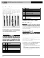
O.D.
Wire
Brush
Reamer
Rack and Pinion
Measuring
Scale
Guard
Adjustable
Handle
Handle
Warning Label

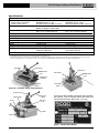
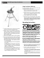
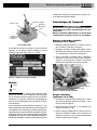
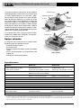
Figure 2B – 122XL Copper Cutting and Prep Machine
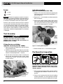
The machine serial number is located on the rear side of
the machine. The last 4 digits indicate the month and
year of the manufacture. (08 = month, 15 = year).
Figure 3 – Machine Serial Number
Figure 1B – 122 Copper Cutting and Prep Machine
Figure 2A – 122XL Copper Cutting and Prep Machine
999-998-069.10_REV. C
5
122/122XL Copper Cutting and Prep Machines
Parameter 122 122XL
Capacity
1
/
2
" to 2" (12 mm to 54 mm)
1
/
2
" to 4" (12 mm to 108 mm)
Copper Tubes and Fittings ASTM B88 Type K, L & M ASTM B88 Type K, L & M
Stainless Steel Tubes Max Wall Thickness 0.065” (1.65 mm) Max Wall Thickness 0.065” (1.65 mm)
Cutter Wheel Model 2191 HD (STD 115V) Model 122 SS
Model 122 SS (STD, 100V, 230V)
Reamer Single Flute Cone, Single Flute Cone,
RH
1
/
2
" to 2" (12 mm to 54 mm) RH
1
/
2
" to 2" (12 mm to 54 mm)
Roller Speed 450 rpm 300 rpm
Motor Type Induction Motor Induction Motor
Motor Rating 100V 100/200V, 50 Hz, 5.4/2.7 Amp
Motor Rating 115V 115V, 60 Hz, 1/3 HP, 3.2 Amp 115V, 60 Hz, 1/3 HP, 3.2 Amp
Motor Rating 220V-240V 220-240VAC, 50/60Hz, 2.2 Amp 220-240VAC, 50/60Hz, 2.2 Amp
Switch Toggle On/Off Toggle On/Off
Weight 50 lb (22,7 kg) 72 lb (32,7 kg)
Dimensions (HxLxW) 14.6" x 16.8" x 15.1" 16.5" x 17.1" x 15.0"
(370 x 427 x 383 mm) (419 x 434 x 381 mm)
Sound Pressure (L
PA
)* 75 dB(A), K=3 75 dB(A), K=3
Specifications
Cutter Wheel
Guide Rollers
ON/OFF Switch
Motor-Driven
Rollers
O.D.
Wire
Brush
Reamer
Rack and Pinion
Measuring
Scale
Guard
Adjustable
Handle
Handle
Cutter Wheel
Guide Rollers
ON/OFF Switch
Motor-Driven
Rollers
Fitting Brushes
and Holder
Warning Label
* Sound measurements are measured in accordance with a standardized test per Standard EN 62481-1.
- Sound emissions may vary due to your location and specific use of these tools.
- Daily exposure levels for sound need to be evaluated for each application and appropriate safety measures taken when needed. Evaluation of exposure levels
should consider the time a tool is switched off and not in use. This may significantly reduce the exposure level over the total working period.
Vent
Vent

Icons
Selection of appropriate materials and instal-
lation, joining and forming methods is the responsibility of
the system designer and/or installer. Selection of improp-
er materials and methods could cause system failure.
Stainless steel and other corrosion resistant materials
can be contaminated during installation, joining and form-
ing. This contamination could cause corrosion and pre-
mature failure. Careful evaluation of materials and methods
for the specific service conditions, including chemical and
temperature, should be completed before any installation
is attempted.
Tool Assembly
WARNING
To reduce the risk of serious injury during use, fol-
low these procedures for proper assembly.
ON/OFF switch should be OFF and machine un -
plugged before assembly.
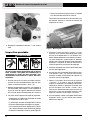
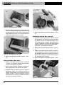
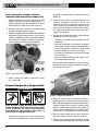
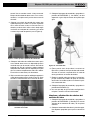
Fitting Brushes and Holder
(optional accessory for the 122XL)
1. Mount the fitting brush holder to the side of machine
using provided screws
2. Attach the quick-change collet (Figure 4) to the front
roller shaft extending from machine housing using the
setscrew. Securely tighten with
1
/
4
" hex key.
3. Pull the collar of the collet to unlock and insert the
brush shank, then release the collar to lock. Make
sure the brush is secure. The brush can be replaced
in similar manner.
Figure 4 – Collet Installed
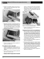
O. D. Deburring Disk
(optional accessory for the 122)
1. Hold the O.D. brush shaft stationary by gripping the
flats located near the surface of the housing with a
9
/
16
"
wrench (Figure 5).
2. Remove the
1
/
2
" nut and washer, and then remove the
brush and spacer.
3. With the disk model number (F-4697) recess facing
the machine housing, slide the deburring disk onto the
shaft and replace the brush. Spacer should not be
used when the deburring disk is installed.
Figure 5 – Installing Deburring Disk
4. Reinstall washer and
1
/
2
" nut and securely tighten.
Pre-Operation Inspection
WARNING
Before each use, inspect your Copper Cutting and
Prep Machine and correct any problems to reduce
the risk of serious injury from electric shock, entan-
glement, crushing and other causes and prevent
machine damage.
1. Make sure that the copper cutting and prep machine
is unplugged and the ON/OFF switch is in OFF (O)
position.
2. Clean any oil, grease or dirt from the tool including
handles and controls. This aids inspection and helps
prevent the tool or control from slipping from your grip.
999-998-069.10_REV. C
6
122/122XL Copper Cutting and Prep Machines
Brush
Brush
Holder
Quick-change Collet
Set
Screw
Flat
Brush
Shaft
Deburring
Disk
(Recess
towards
machine)
NOTICE
Power ON
Power OFF

999-998-069.10_REV. C
7
8. After the inspection is complete, move the ON/OFF
switch into the OFF (O) position and, with dry hands,
unplug the machine.
Machine and Work Area Set-Up
WARNING
Set up the Copper Cutting and Prep Machine and
work area according to these procedures to reduce
the risk of injury from electrical shock, entanglement,
crushing and other causes and prevent tool damage.
Secure machine to stable bench or stand. Properly
support tube. This will reduce the risk of falling
tube, tipping and serious injury.
Keep fingers and hands away from the rotating
ream er, rollers, wire brush, deburring disk and tube.
Reduces the risk of entanglement and cutting in -
juries.
1. Check work area for:
• Adequate lighting.
• Flammable liquids, vapors or dust that may ignite. If
present, do not work in area until sources have
been identified and corrected. The copper cutting
and prep machine is not explosion proof and can
cause sparks.
• Clear, level, stable, dry place for operator. Do not
use the machine while standing in water.
• Properly grounded electrical outlet of the correct
voltage. A three-prong or GFCI outlet may not be
properly grounded. If in doubt, have outlet inspect-
ed by a licensed electrician.
• Clear path to electrical outlet that does not contain
any potential sources of damage for the power cord.
2. Inspect the work to be done. Determine the material,
type and size of the tube. Determine the correct
equipment for the job. See “Specification” section for
tool information.
3. Confirm that the equipment to be used has been
properly inspected.
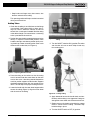
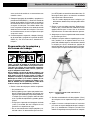
4. Place the machine on a flat, level, stable surface or a
1206 stand. If using a 1206 Stand, set up per its
instructions. Bolt the machine down using the mount-
ing holes located at the rear of the unit. Confirm that
unit is stable and secure.
Clean dirt and debris from the rollers. Rollers must be
kept clean to insure proper machine performance.
3. Inspect the copper cutting and prep machine for the
following items:
• Damage or modification to the cord and plug.
• Proper assembly, maintenance and completeness.
• Damaged, misaligned or binding parts.
• Free movement of adjustable handle, rack and
pinion, cutter wheel and guide rollers
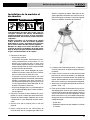
• Presence and readability of the warning label (see
Figure 6).
• Any other condition which may prevent safe and
normal operation.
If any problems are found, do not use the copper
cutting and prep machine until the problems have
been repaired.
Figure 6 – Warning Label
4. Inspect the cutter wheel, reamer, brush(es) and guide
rollers for wear and damage. If necessary, replace prior
to using the machine. Dull, damaged or de formed
tools can lead to uneven cuts or cleaning, excessive
bur formation, and slow the cutting or cleaning process.
5. Inspect and maintain any other equipment being used
per its instructions.
6. Make sure that the ON/OFF switch is set to the OFF
(O) position. With dry hands, plug cord into properly
grounded outlet.
7. Move the ON/OFF switch into the ON (I) position
and note the direction of rotation of the rollers. If the
switch does not control the machine operation, do not
use the machine until the switch has been repaired.
The rollers should rotate counter-clockwise when
viewed from the reamer side of the machine. If the
rotation is not correct, do not use the machine until it
has been repaired.
122/122XL Copper Cutting and Prep Machines

Figure 7 – 122XL on 1206 stand
5. If tube will extend more than 6" beyond the machine,
use one or more stands to support the tube.
6. Restrict access or set-up guards or barricades to
create a minimum of 3 feet (1 m) of clearance around
the machine and tube. This reduces the risk of entan-
glement or tipping from non-operators from contact-
ing the machine or tube.
7. Confirm that the ON/OFF switch is in OFF (O) position.
8. Run the cord along the clear path. With dry hands plug
the copper cutting and prep machine into a properly
grounded outlet. Keep all connections dry. If the power
cord is not long enough, use an extension cord that:
• Is in good condition.
• Has a three-prong plug similar to that supplied on
the machine.
• Is rated for outdoor use and contains a W or W-A in
the cord designation (i.e. SOW), or complies with
H05VV-F, H05RN-F types or IEC type design
(60227 IEC 53, 60245 IEC 57).
• Has sufficient wire size. For extension cords up to
50' (15.2 m) long use 16 AWG (1.5 mm
2
) or heav-
ier. For extension cords 50'-100' (15.2 m – 30.5 m)
long use 14 AWG (2.5 mm
2
) or heavier.
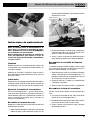
Using Foot Switch (120V only)
For ease of operation, the 122 and 122XL can be used
with Model 301A Foot Switch–120.
1. With dry hands plug the 301A Foot Switch into a
properly grounded outlet or extension cord.
2. Confirm that the 122 or 122XL machine ON/OFF
switch is in OFF (O) position. Plug the 122 or 122XL
machine plug into the foot switch receptor.
3. Turn the ON/OFF switch to ON (I) position.
4. With hands clear of all rotating parts, press the foot
switch and confirm that the foot switch controls the
machine operation. Release the foot switch and let the
machine come to a complete stop. Move the ON/OFF
switch to the OFF (O) position.
Operating Instructions
WARNING
Always wear appropriate eye protection to protect
your eyes against dirt and other foreign objects.
Do not wear gloves or loose clothing. Keep sleeves
and jackets buttoned. Clothing can be caught in
rotating rollers or tools and cause crushing injuries.
Keep fingers and hands away from rotating rollers,
reamer, wire brushes and tube. This reduces the
risk of entanglement and cutting injuries
Properly support long lengths of tubing. This re -
duces the risk of tipping or falling tube.
Do not cut visibly bent tubing or tubing with fit-
tings attached. Reduces the risk of excessive vibra-
tion and loss of control of the tubing.
Follow operating instructions to reduce the risk of
injury from electrical shock, entanglement, crushing
and other causes and prevent machine damage.
1. Confirm that the copper cutting and prep machine and
work area are properly set up and the work area is
free of bystanders and other distractions.
2. Assume a proper operating position to help main-
tain control the machine and process:
• Be sure you have convenient access to the ON/ -
OFF switch or can control the ON/OFF action of the
foot switch if used.
• Be sure that you have good balance, do not have to
overreach, and cannot fall on the machine or other
hazards.
999-998-069.10_REV. C
8
122/122XL Copper Cutting and Prep Machines

Figure 9 – Cutter Wheel Support Rollers Contacting
Tubing
5. Turn the ON/OFF switch to ON (I) position.The rollers
and the tube will start to rotate. Keep hands way
from rotating parts.
Figure 10 – Cutting Tubing
6. Apply downward force to the handle slowly and con-
tinuously until the tubing is cut. Aggressive cutting can
damage the cutter wheel and cause excessive burrs.
7. Reduce force on the handle maintaining the support
rollers in contact with the tubing. The rollers help
hold the tubing in place.
8. Turn the ON/OFF switch to OFF (O) position.
• Keep hands and fingers away from reamer, wire
brushes and ends of the tubing.
This operating position will help to maintain control of
tubing and the machine.
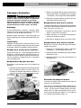
Cutting Tubes
1. Check that the tubing is not visibly bent and no fittings
are attached. Cutting bent tubes or tubes with fit-
tings can result in excessive vibration and loss of
control. Use a hand cutter if needed. Mark the tubing
at the desired length. For convenience, a measuring
scale is provided on the machine.
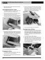
2. Position the cutter handle to provide clearance for the
tubing. To adjust the cutter wheel position, move
handle to the right and relocate position pin by mov-
ing handle up or down according to the arrow marks
shown on the handle label (see Figure 8).
Figure 8 – Adjusting Handle Position
3. Place the tubing on the rollers so that the cutting
mark is located under the cutter wheel, on the zero
mark of the scale. If the tubing extends beyond the
machine, position supports under the tube. Supports
should be adjusted so the tube sits squarely on the
rollers. This will help insure proper tracking of the cut.
4. Lower the handle until the cutter wheel support rollers
contact the tubing (Figure 9). Align the cutter wheel
with the mark on the tubing.
999-998-069.10_REV. C
9
122/122XL Copper Cutting and Prep Machines

3. Place the tubing over the reamer cone and gently
apply pressure (Figure 13). Do not force the tube
into the reamer. This will remove burrs from inside of
the tubing. The maximum reaming capacity is 2" (54
mm) tubing. Do not try to deburr larger tubes.
Figure 13 – Reaming I.D. of Tube
4. Turn the ON/OFF switch to OFF (O) position.
Cleaning Inside of Fittings
1. Check that the installed brush is the correct size for the
fitting diameter. New brushes (up to 3" size) are sim-
ilar in size to the tube O.D. If needed, install correct
size fitting brush on the quick-change collet as
described in “Fitting Brushes and Holder” section of
Tool Assembly.
2. Turn ON/OFF switch to ON (I) position.
3. Keep fingers away from brush. Push fitting over the
rotating brush (Figure 14). Hold the fitting securely to
prevent rotation and press O.D. of the fitting against the
O.D. of the brush. Continue until fitting I.D. is clean,
then pull fitting off of brush.
4. Turn the ON/OFF switch to OFF (O) position.
Figure 14 – Cleaning Inside of Fittings
999-998-069.10_REV. C
10
122/122XL Copper Cutting and Prep Machines
9. When tubing stops rotating, remove from the machine.
Raise the cutter handle.
Cleaning/Deburring O.D. of Tube
1. Turn ON/OFF switch to ON (I) position. Keep hands
away from the tube ends and rotating parts.
2. Place the end of tube on the rest plate. Properly
support the tube to help maintain control.
3. For cleaning: Gently press the tube against the brush
and rotate slowly until the surface is bright (Figure 11).
Figure 11 – Cleaning Tube O.D.
4. For deburring: Gently press the tube end against the
deburring disk to remove external burrs. Rotate the tube
against deburring disk (Figure 12). This also bev els the
end of the tube for easier insertion into fitting.
Figure 12 – Deburring O.D. Of Tube
5. Turn the ON/OFF switch to OFF (O) position.
Reaming I.D. of Tube
1. Turn ON/OFF switch to ON (I) position. Keep hands
away from tube ends and rotating parts.
2. Securely grasp the tube. Properly support the tube to
help maintain control.

2. Remove cutter wheel screw and replace the cutter
wheel (Figure 15). See Accessories section for avail-
able cutter wheels.
3. Reinstall the roller and slide assembly and securely
tighten the shoulder bolt.
O.D. Brush Replacement
The O.D. Brush should be replaced when its bristles
become uneven or too short to effectively clean the tubing.
See Figure 5.
1. Hold the O.D. brush shaft stationary by gripping the flat
located near the surface of the housing with a
9
/
16
"
wrench.
2. Remove the
1
/
2
" nut and washer from the shaft and
replace the brush.
3. Reinstall washer and nut and securely tighten.
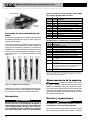
Reamer Blade Replacement
Replace reamer blade if it is damaged or dull.
1. Remove reamer from its shaft by loosening set screw
with a
5
/
32
" hex key.
2. Unscrew two cap screws that hold the blade to the
reamer cone. Replace the blade
3. Reinstall reamer onto the shaft and secure with
5
/
16
" set
screw.
Figure 16 – Reamer
999-998-069.10_REV. C
11
122/122XL Copper Cutting and Prep Machines
Maintenance Instructions
WARNING
Make sure that the ON/OFF switch is in the OFF
position and the machine is unplugged before per-
forming any maintenance or making any adjust-
ments.
Maintain tool according to these procedures to
reduce the risk of injury from electrical shock,
entanglement and other causes.
Cleaning
Gently clean the machine after each use with a clean dry
cloth. Keep the rollers clean and free from dirt and debris.
Keep the reamer, brush, cutter wheel and deburring disk
clean and free from chips for maximum efficiency.
Lubrication
Keep a light coat of lubricating oil on the rack and pinion,
the cutter wheel shaft, and the guide roller shafts. Wipe up
any excess oil.
Adusting Rack Tension
Use a
5
/
32
" hex key to tighten or loosen rack tension set
screw (Figure 15) as desired. Typically it is set just tight
enough to prevent rack movement under it’s own weight.
Cutter Wheel Replacement
Replace the cutter wheel when the cutting edge becomes
chipped or flat.
1. Loosen the shoulder bolt and remove the roller and
slide assembly (Figure 15). Do not remove the shoul-
der bolt, this keeps the tension spring in place.
Figure 15 – Remove Cutter Wheel Screw
Shoulder
Screw
Cutter
Wheel
Roller Slide
Assembly
Rack Tension
Set Screw
Set Screw
Reamer
Blade

999-998-069.10_REV. C
12
122/122XL Copper Cutting and Prep Machines
Motor Thermal Overload
The motor is equipped with a thermal overload that turns
off the motor if it gets too hot.
To reset the thermal overload, unplug machine and turn
ON/OFF switch to the OFF (O) position and allow the
motor to cool for 15 minutes. Use a thin, non-conductive
probe to reach through the vent (Figures 1 and 2) to
press the reset button (Figure 17).
Figure 17 – Motor Reset Button
If motor does not start or the thermal overload continual-
ly trips during normal operation, the machine should be
taken to RIDGID Authorized Service Center.
Accessories
WARNING
To reduce the risk of serious injury, only use acces-
sories specifically designed and recommended for
use with the 122 and 122XL Copper Cutting and
Prep Machines such as those listed below. Other
Accessories suitable for use with other tools may be
hazardous when used with the 122 and 122XL
Copper Cutting and Prep Machines.
Further information on accessories specific to this tool can be found in
the RIDGID Catalog and online at RIDGID.com or RIDGID.eu
Machine Storage
The 122 and 122XL Copper Cutting and
Prep Machines must be kept indoors or well covered in
rainy weather. Store the machine in a locked area that is
out of reach of children and people unfamiliar with the
machines. These machines can cause serious injury in the
hands of untrained users.
Service and Repair
WARNING
Improper service or repair can make machine
unsafe to operate.
The “Maintenance Instructions” will take care of most of
the service needs of this machine. Any problems not
addressed by this section should only be handled by an
authorized RIDGID service technician.
Tool should be taken to a RIDGID Independent Service
Center or returned to the factory.
For information on your nearest RIDGID Independent
Service Center or any service or repair questions:
• Contact your local RIDGID distributor.
• Visit RIDGID.com to find your local RIDGID contact
point.
• Contact Ridge Tool Technical Service Department at
rtctechservices@emerson.com or in the U.S. and
Canada call (800) 519-3456
Catalog Model
No. No. Description
33175 2191 Cutter Wheel for Copper
34360 — Wheel Screw for 2191 Cutter Wheel
33551 122SS Cutter Wheel for Copper and Stainless Steel
10343 — Wheel Pin for 33551 Cutter Wheel
46105 — O.D. Deburring Disk
94682 — O.D. Cleaning Brush
94687 — 2" Reamer Cone Assembly
36662 301A Model 301A Foot Switch – 120V Only
42360 1206 1206 Stand
94692 — Reamer Blade
WARNING
Catalog
No. Description
93747 Quick-Change Collet
93717
1
/
2
" Fitting Brush (3 Per Pack)
93722
3
/
4
" Fitting Brush (3 Per Pack)
93727 1" Fitting Brush (3 Per Pack)
93732 1
1
/
4
" Fitting Brush (3 Per Pack)
93737 1
1
/
2
" Fitting Brush (3 Per Pack)
93742 2" Fitting Brush (3 Per Pack)
12638 2
1
/
2
" Fitting Brush (3 Per Pack) – 122XL Only
12643 3" - 4" Fitting Brush (3 Per Pack) – 122XL Only
93707 Fitting Brush Storage Kit Includes Mountable Storage Rack,
Quick-Change Collet, Spare Cutter Wheel and Brushes
(
1
/
2
",
3
/
4
", 1", 1
1
/
4
", 1
1
/
2
, 2")
93712 Fitting Brush Holder
Fitting Brush and Holder
Red Reset
Button

999-998-069.10_REV. C
13
122/122XL Copper Cutting and Prep Machines
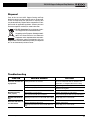
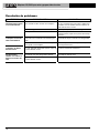
SYMPTOM POSSIBLE REASONS SOLUTION
Excessive vibration dur-
ing operation.
Machine not cutting
tubes properly.
Machine stalls while cut-
ting.
Excessive tube burrs or
end deformation.
Troubleshooting
Cutting bent tubes on machine.
Long tubes not properly supported.
Machine not properly mounted.
Worn blades or cutter wheel.
Use on incorrect tube size or material.
Applying excessive force on the handle while cutting.
Worn or damaged cutter wheel.
Applying excessive force on the handle while cut-
ting.
Do not cut visibly bent tubes on machine. Use
hand cutter, or straighten tubes before cutting.
Support longer tubes with pipe stands.
Properly mount the machine on flat surface, bolt
with the mounting bolts.
Replace worn blades or cutter wheel.
Use on correct type of tubes (see Specifications).
Gently apply force on the handle.
Replace cutter wheel.
Gently apply force on the handle.
Disposal
Parts of the 122 and 122XL Copper Cutting and Prep
Machines contain valuable materials and can be recycled.
There are companies that specialize in recycling that
may be found locally. Dispose of the com ponents in com-
pliance with all applicable regulations. Contact your local
waste management authority for more information.
For EC Countries: Do not dispose of elec-
trical equipment with household waste!
According to the European Guideline 2002/ -
96/ EC for Waste Electrical and Electronic
Equipment and its implemen tation into nation-
al legislation, electrical equipment that is no
longer usable must be collected separately and disposed
of in an environmentally correct manner.

999-998-069.10_REV. C
14
122/122XL Copper Cutting and Prep Machines

Machines de coupe et de préparation du cuivre
Notez ci-dessous le numéro de série indiqué sur la plaque signalétique de l’appareil pour future
référence.
N° de
série
Machines de coupe et de
préparation du cuivre
122/122XL : Mode d’emploi
122
122XL
AVERTISSEMENT
Familiarisez-vous avec ce mode
d’emploi avant d’utiliser l’appareil.
Tout manque de compréhension
ou de respect des consignes ci-
après augmenterait les risques de
choc électrique, d’incendie et/ou
de graves lésions corporelles.

999-998-069.10_REV. C
16
Machines de coupe et de préparation du cuivre
Table des matières
Fiche d’enregistrement du numéro de série de la machine....................................................................................15
Symboles de sécurité ................................................................................................................................................17
Consignes de sécurité générales applicables aux appareils électriques
Sécurité des lieux......................................................................................................................................................17
Sécurité électrique ....................................................................................................................................................17
Sécurité individuelle ..................................................................................................................................................18
Utilisation et entretien des appareils électriques ......................................................................................................18
Service après-vente ..................................................................................................................................................19
Consignes de sécurité spécifiques
Sécurité des machines de coupe et de préparation du cuivre ..................................................................................19
Description, caractéristiques techniques et équipements de base
Description ................................................................................................................................................................19
Equipements de base ..............................................................................................................................................20
Caractéristiques techniques......................................................................................................................................20
Icones ......................................................................................................................................................................21
Assemblage de l’appareil
Montage des brosses et du porte-brosses................................................................................................................21
Disque d’ébarbage externe ......................................................................................................................................21
Inspection préalable....................................................................................................................................................22
Préparation de la machine et des lieux ....................................................................................................................23
Utilisation de la pédale de commande (modèle 120V uniquement)..........................................................................24
Consignes d’utilisation
Coupe des tubes et tuyaux ......................................................................................................................................24
Nettoyage et ébarbage externe des tubes................................................................................................................25
Alésage des tubes ....................................................................................................................................................26
Nettoyage interne des raccords ................................................................................................................................26
Consignes d’entretien
Nettoyage..................................................................................................................................................................27
Lubrification ..............................................................................................................................................................27
Réglage de la crémaillère ........................................................................................................................................27
Remplacement du galet de coupe ............................................................................................................................26
Remplacement de la brosse externe ........................................................................................................................27
Remplacement de la lame d’alésoir..........................................................................................................................27
Protection thermique du moteur................................................................................................................................27
Accessoires ................................................................................................................................................................28
Stockage ......................................................................................................................................................................28
Révisions et réparations ............................................................................................................................................28
Recyclage ....................................................................................................................................................................29
Dépannage ..................................................................................................................................................................29
Déclaration de conformité CE ..............................................................................................recto de la page de garde
Garantie à vie ..........................................................................................................................................page de garde
*Traduction de la notice originale

999-998-069.10_REV. C
17
Consignes générales de
sécurité applicables aux
appareils électriques*
AVERTISSEMENT
Familiarisez-vous avec l’ensemble des consignes
de sécurité, instructions, illustrations et carac-
téristiques techniques fournies avec cet appareil
électrique. Le non-respect des consignes ci-dessous
augmenterait les risques de choc électrique, d’in -
cendie et/ou de grave blessure corporelle.
Conservez l’ensemble des consignes de sécu-
rité et d’utilisation pour future référence !
Le terme « appareil électrique » utilisée dans les con-
signes de sécurité s’applique à la fois aux appareils élec-
trique sur secteur et à piles.
Sécurité des lieux
• Assurez-vous de la propreté et du bon éclairage
des lieux. Les chantiers encombrés ou mal éclairés
sont une invitation aux accidents.
• N’utilisez pas d’appareils électriques en présence
de substances volatiles telles que liquides, gaz ou
poussières combustibles. Ce type de matériel risque
de produire des étincelles susceptibles d’enflammer les
poussières et émanations combustibles.
• Eloignez les enfants et les curieux durant l’utili -
sation des appareils électriques. Les distractions
risquent de vous faire perdre le contrôle de l’appareil.
Sécurité électrique
• La fiche du cordon d’alimentation de l’appareil doit
être adaptée à la prise de courant utilisée. Ne jamais
utiliser d’adaptateur sur un appareil électrique avec
terre. L’emploi de fiches non modifiées et de prises
appropriées limitera les risques de choc électrique.
• Evitez tout contact avec des objets reliés à la terre
Symboles de sécurité
Les symboles et mots clés utilisés à la fois dans ce mode d’emploi et sur l’appareil lui-même servent à signaler
d’importants risques de sécurité. Ce qui suit permettra de mieux comprendre la signification de ces mots clés et symboles.
DANGER
Ce symbole sert à vous avertir de risques d’accident potentiels. Le respect des consignes qui le suivent vous permettra d’éviter
les risques d’accident grave ou potentiellement mortel.
Le terme DANGER signifie une situation dangereuse qui, faute d’être évitée, provoquerait la mort ou de graves
blessures corporelles.
AVERTISSEMENT
Le terme AVERTISSEMENT signifie une situation dangereuse potentielle qui, faute d’être évitée, serait sus-
ceptible d’entraîner la mort ou de graves blessures corporelles.
ATTENTION
Le terme ATTENTION signifie une situation dangereuse potentielle qui, faute d’être évitée, serait susceptible
d’entraîner des blessures corporelles légères ou modérées.
Le terme AVIS IMPORTANT indique des informations concernant la protection des biens.
Ce symbole indique la nécessité de bien se familiariser avec la notice d’emploi avant d’utiliser ce matériel. La notice
d’emploi renferme d’importantes consignes de sécurité et d’utilisation du matériel.
Ce symbole impose le port systématique de lunettes de sécurité à ?illères lors de la manipulation ou utilisation de ce matériel
afin de limiter les risques de lésion oculaire.
Ce symbole signale un risque d’entraînement des doigts, jambes, vêtements ou autres objets portés dans le mécanisme.
Ce symbole signale un risque de coupure des mains des doigts ou autres parties du corps en cas de contact avec un alésoir,
une brosse rotative ou autre mécanisme.
AVIS IMPORTANT
Ce symbole signale un risque de blessure en cas de renversement de l’appareil.
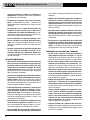
Ce symbole interdit le port de gants lors de l’utilisation de la machine afin de limiter les risques d’enchevêtrement.
Ce symbole signale un risque de choc électrique.
Machines de coupe et de préparation du cuivre
* Imposé d’office, le texte utilisé dans la section intitulée « Consignes générales de sécurité applicables aux appareils électriques » de ce manuel est extrait verbatim
de la norme EN 62841-1. Cette section couvre des mesures de sécurité générales applicables à de nombreux types d’appareils électriques divers. Les consignes
affichées ne sont pas nécessairement applicables à l’ensemble des appareils, et certaines d’entre-elles ne sont pas applicables à cet appareil.

18
tels que canalisations, radiateurs, cuisinières et
réfrigérateurs. Tout contact avec la terre augmenterait
les risques de choc électrique.
• N’exposez pas l’appareil à la pluie ou aux intem-
péries. Toute pénétration d’eau à l’intérieur d’un
appareil électrique augmenterait les risques de choc
électrique.
• Ne maltraitez pas le cordon d’alimentation de
l’appareil. Ne jamais porter, tirer ou débrancher
l’appareil par son cordon d’alimentation. Les cor-
dons d’alimentation endommagés ou entortillés aug-
mentent les risques de choc électrique.
• Lors de l’utilisation d’un appareil électrique à l’ex -
térieur, prévoyez une rallonge électrique appro-
priée. Les rallonges électriques prévues pour une
utilisation à l’extérieur limitent les risques de choc
électrique.
• Lorsque l’utilisation d’un appareil électrique dans
un lieu humide est inévitable, prévoyez une ali-
mentation équipée d’un disjoncteur différentiel.
L’utilisation d’un disjoncteur différentiel limite les risques
de choc électrique.
Sécurité individuelle
• Soyez attentif, restez concentré et faites preuve de
bon sens lors de l’utilisation de ce type d’appareil.
Ne jamais utiliser ce matériel lorsque vous êtes
fatigué ou sous l’influence de drogues, de l’alcool
ou de médicaments. Lors de l’utilisation d’un appareil
électrique, un instant d’inattention risque d’entraîner
de graves lésions corporelles.
• Prévoyez les équipements de protection individu-
elle appropriés. Portez systématiquement une pro-
tection oculaire. Selon le cas, le port d’un masque à
poussière, de chaussures de sécurité antidérapantes,
du casque ou d’une protection auriculaire peut aider à
limiter les risques de lésion corporelle.
• Evitez les démarrages accidentels. Assurez-vous
que l’interrupteur se trouve en position « arrêt »
avant de brancher l’appareil, d’y introduire un bloc-
piles ou de le porter. Le fait de porter un appareil élec-
trique avec son doigt sur la gâchette ou de l’alimenter
lorsque son interrupteur est en position « marche » est
une invitation aux accidents.
• Retirez toute clé ou dispositif de réglage éventuel
avant de mettre l’appareil en marche. Une clé ou
tout autre dispositif de réglage engagé sur un élé-
ment mécanique pourrait provoquer un accident.
• Ne vous mettez pas en porte-à-faux. Maintenez une
bonne assiette et un bon équilibre à tout moment.
Cela assurera un meilleur contrôle de l’appareil en cas
d’imprévu.
• Habillez-vous de manière appropriée. Ne portez ni
accessoires, ni bijoux. Eloignez vos cheveux, vos
vêtements et vos gants des mécanismes lorsque
l’appareil fonctionne. Les foulards, les bijoux et les
cheveux longs risquent d’être entraînés par les mécan-
ismes en rotation.
• En présence d’un système d’extraction et de récu -
pération de poussière, assurez-vous que celui-ci
est correctement raccordé et utilisé. La récupération
de poussière peut limiter les risques d’incidents liés à
la poussière.
• Ne laissez pas la familiarité issue d’une utilisation
fréquente de l’appareil vous rendre complaisant
au point d’ignorer les principes de sécurité appli-
cables. Le moindre faux-pas peut occasionner de
graves blessures dans une fraction de seconde.
Utilisation et entretien de l’appareil
• Ne pas forcer l’appareil. Prévoyez l’appareil le
mieux adapté aux travaux envisagés. Un appareil
adapté produira de meilleurs résultats et un meilleur
niveau de sécurité lorsqu’il fonctionne au régime prévu.
• Ne pas utiliser d’appareil dont l’interrupteur mar -
che/arrêt ne fonctionne pas correctement. Tout
appareil qui ne peut pas être contrôlé par son inter-
rupteur est considéré dangereux et doit être réparé.
• Débranchez l’appareil et/ou retirez son bloc-piles
amovible avant tout réglage, changement d’acces-
soires ou stockage de l’appareil. De telles mesures
de sécurité préventives limiteront les risques de démar-
rage accidentel de l’appareil.
• Ranger tout appareil non utilisé hors de la portée
des enfants. L’utilisation de cet appareil doit être
exclusivement réservé à du personnel compétent.
Ce type d’appareil peut devenir dangereux entre les
mains d’un novice.
• Assurer l’entretien approprié de l’appareil. S’assur-
er de l’absence d’éléments grippés ou endom-
magés, voire toute autre anomalie susceptible de
nuire au bon fonctionnement et à la sécurité de
l’appareil. Ne pas utiliser d’appareil en dommage
avant sa réparation. De nombreux accidents sont le
résultat d’ap pareils mal entretenus.
• Assurez l’entretien de l’appareil et de ses acces-
soires. Des outils de coupe correctement entretenus
et affutés sont moins susceptibles de se gripper et sont
plus faciles à contrôler.
Machines de coupe et de préparation du cuivre
La page est en cours de chargement...
La page est en cours de chargement...
La page est en cours de chargement...
La page est en cours de chargement...
La page est en cours de chargement...
La page est en cours de chargement...
La page est en cours de chargement...
La page est en cours de chargement...
La page est en cours de chargement...
La page est en cours de chargement...
La page est en cours de chargement...
La page est en cours de chargement...
La page est en cours de chargement...
La page est en cours de chargement...
La page est en cours de chargement...
La page est en cours de chargement...
La page est en cours de chargement...
La page est en cours de chargement...
La page est en cours de chargement...
La page est en cours de chargement...
La page est en cours de chargement...
La page est en cours de chargement...
La page est en cours de chargement...
La page est en cours de chargement...
La page est en cours de chargement...
La page est en cours de chargement...
La page est en cours de chargement...
La page est en cours de chargement...
La page est en cours de chargement...
La page est en cours de chargement...
La page est en cours de chargement...
La page est en cours de chargement...
-
 1
1
-
 2
2
-
 3
3
-
 4
4
-
 5
5
-
 6
6
-
 7
7
-
 8
8
-
 9
9
-
 10
10
-
 11
11
-
 12
12
-
 13
13
-
 14
14
-
 15
15
-
 16
16
-
 17
17
-
 18
18
-
 19
19
-
 20
20
-
 21
21
-
 22
22
-
 23
23
-
 24
24
-
 25
25
-
 26
26
-
 27
27
-
 28
28
-
 29
29
-
 30
30
-
 31
31
-
 32
32
-
 33
33
-
 34
34
-
 35
35
-
 36
36
-
 37
37
-
 38
38
-
 39
39
-
 40
40
-
 41
41
-
 42
42
-
 43
43
-
 44
44
-
 45
45
-
 46
46
-
 47
47
-
 48
48
-
 49
49
-
 50
50
-
 51
51
-
 52
52


RIDGID 10973 Manuel utilisateur
- Catégorie
- Outils électroportatifs
- Taper
- Manuel utilisateur
dans d''autres langues
- English: RIDGID 10973 User manual
- español: RIDGID 10973 Manual de usuario
Documents connexes
-
RIDGID 122XL Manuel utilisateur
-
RIDGID 975 Manuel utilisateur
-
RIDGID เครื่องมือตัดท่อสำหรับงานหนัก Manuel utilisateur
-
RIDGID 300 Compact Manuel utilisateur
-
-
-
-
RIDGID 37835 Manuel utilisateur
-
-
