Minebea Intec YSB02 Digital Input/Output Module for RS-485 Interface Guide d'installation
- Taper
- Guide d'installation

Installation Instructions | Betriebsanleitung | Notice d’installation
Instrucciones de instalación | Istruzioni per l’installazione
Minebea Intec YSB02
Digital Input/Output Module for RS-485 Interface
Digitales Ein-/Ausgabemodul für RS485 Anschluss
Module d’entrée/sortie numérique pour interface RS485
Módulo E/S digital para conexión de interfaz RS485
Modulo di ingresso/uscita digitale per interfaccia RS485
98647-003-45
98647-003-45

2 Installation Instructions | Installationsanleitung Installation Instructions | Installationsanleitung 3
English - page 3
Deutsch - Seite 8
Français – page 13
Español – página 18
Italiano - pagina 23

2 Installation Instructions | Installationsanleitung Installation Instructions | Installationsanleitung 3
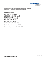
Note:
Before installing and using the digital
input/output module, make sure to
read the manufacturer’s instruction
manual provided with the module.
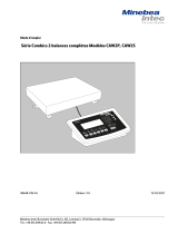
PLC
7 inputs 8 outputs
YSB02
Power supply
provided by
customer
(+10 V to
+30 V DC)
RS-485
English
Intended Use
The digital input/output module con-
verts serial control signals into parallel
control signals.
This module is designed for connection
to the RS-485 interface port on the
Combics 3 indicator. With this digital
I/O module, activation of servo-compo-
nents and process control tasks can be
carried out via a PLC, for example, that
sets or loads parallel signals.
The YSB02 module has been prepared
at the factory for installation on a top-
hat rail.
The digital input/output module is
connected to the RS-485 interface on
the Combics 3 indicator using either
customer equipment or a connecting
cable available from Minebea Intec :
– YCC02-RELAIS01 for connection to
Combics 3, Option H4 (Filling with
Extras)
– YCC02-RELAIS02 for connection to
Combics 3, Option H4 (Filling with
Extras)

4 Installation Instructions | Installationsanleitung Installation Instructions | Installationsanleitung 5
English
Pin Assignments
Pin Designation Description Function (assigned in
Minebea Intec operating
menu)
1 DO 7 Digital output 7 Digital output 8
2 DO 6 Digital output 6 Digital output 7
3 DO 5 Digital output 5 Digital output 6
4 DO 4 Digital output 4 Digital output 5
5 DO 3 Digital output 3 Digital output 4
6 DEFAULT* Default
7 (Y)DATA+ RS-485 signal, positive
8 (G)DATA- RS-485 signal, negative
9 (R)+VS Supply voltage
10 (B)GND Ground
11 DO 2 Digital output 2 Digital output 3
12 DO 1 Digital output 1 Digital output 2
13 DO 0 Digital output 0 Digital output 1
14 DI 0 Digital input 0 Digital input 1
15 DI 1 Digital input 1 Digital input 2
16 DI 2 Digital input 2 Digital input 3
17 DI 3 Digital input 3 Digital input 4
18 DI 4 Digital input 4 Digital input 5
19 DI 5 Digital input 5 Digital input 6
20 DI 6 Digital input 6 Digital input 7

4 Installation Instructions | Installationsanleitung Installation Instructions | Installationsanleitung 5
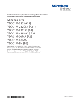
Cabling Diagram for Optional Cable: YCC02-RELAIS01
YSB02 YCC02-RELAIS01
Designation Pin Cable Label 25-pin D-Sub male
ends connector
(Y) DATA+ 7 RS-485+ RS-485+ (TxD-RxD+) (2)
GND GND (7)
(G)DATA- 8 RS-485- RS-485- (TxD-RxD-) (20)
MINOR < (16)
PARES = (17)
MAJOR > (18)
SET SET (19)
UNI_IN UNI_IN (15)
COM COM (21)
LINE LINE (24)
(1)
Connection between YSB02, VF3033 and COM2 from Combics3:
YSB02/VF3033
Connection between YSB02, VF3033 and UniCom from Combics3:
YSB02/VF3033
Isolate unused cable ends in accordance with industry standards.
5
Cabling Diagram for Optional Cable: YCC02-RELAIS01
YSB02 YCC02-RELAIS01
Designation Pin Cable Label 25-pin D-Sub male
ends connector
(Y) DATA+ 7 RS-485+ RS-485+ (TxD-RxD+) (2)
GND GND (7)
(G)DATA- 8 RS-485- RS-485- (TxD-RxD-) (20)
MINOR < (16)
PARES = (17)
MAJOR > (18)
SET SET (19)
UNI_IN UNI_IN (15)
COM COM (21)
LINE LINE (24)
(1)
Connection between YSB02, VF3033 and COM2 from Combics3 (CISL3):
YSB02/VF3033
(Y) Data + (7) RS485+ RS485+ (3)
(G) Data - (8) RS485- RS485- (5)
(1)
Connection between YSB02, VF3033 and UniCom from Combics3 (CISL3):
YSB02/VF3033
(Y) Data + (7) RS485+ URS485+ (16)
(G) Data - (8) RS485- URS485- (9)
(1)
Isolate unused cable ends in accordance with industry standards.

6 Installation Instructions | Installationsanleitung Installation Instructions | Installationsanleitung 7
English
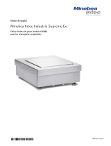
Cabling Diagram for Optional Cable: YCC02-RELAIS02
YSB02 YCC02-RELAIS02
Designation Pin Cable Label Label
ends
(Y) DATA+ 7 RS-485+ RS-485+
GND GND
(G)DATA- 8 RS-485- RS-485-
MINOR MINOR
PARES PARES
MAJOR MAJOR
SET SET
UNI_IN UNI_IN
GND 10 COM COM
(R)+VS 9 LINE LINE
Connect the cable in accordance with the pin assignments specified for the Combics
indicator. Unused cable ends can be isolated and encased in shrink-down tubing.

6 Installation Instructions | Installationsanleitung Installation Instructions | Installationsanleitung 7
Specifications
Interface:
– Interface: RS-485 –
Baud rate: 9600
– Data bytes: 8
– Stop bits: 1
– Parity: None
– Module address: 0 through 9 available
Digital inputs:
– Number: 7
– Low level: 0 to +0.7 V
– High level: +3.5 to +30 V
– Internal pull-up resistor: 10 kOhms
– Max. power consumption: 0.5 mA
– Inputs switched through application of corresponding voltage or through switching
the input against GND
Digital outputs:
– Number: 8
– Maximum current flow per channel: 50 mA
– Maximum power consumption
for all channels: 300 mW
– Each output is formed by an open-collector transistor
Supply voltage: +10 V DC to +30 V DC
Current consumption: 30 mA
Power consumption: 400 mW
Allowable storage temperature: -25°C to +80°C (-13°F to +176°F)
Operating temperature range: -10°C to +70°C (+14°F to +158°F)

8 Installation Instructions | Installationsanleitung Installation Instructions | Installationsanleitung 9
Deutsch
Hinweis
Für die Verwendung und Inbetriebnah-
me des digitalen Ein-/Ausgabemoduls
ist auch die dem Modul beiliegende
Betriebsanleitung des Herstellers zu
beachten.
SPS
7 Eingänge 8 Ausgänge
YSB02
Spannungs-
versorgung
kundenseitig
(+10 V bis
+30 V DC)
RS485
Verwendungszweck
Das digitale Ein-/Ausgabemodul dient
der Umwandlung serieller Steuerkom-
mandos in parallele Steuersignale.
Es wird an die RS485 Schnittstelle eines
Combics 3 Auswertegerätes angeschlos-
sen. Die Ansteuerung der Stellglieder
und die weitere Prozesssteuerung
erfolgt z.B. über eine SPS, die die paral-
lelen Steuersignale setzt oder einliest.
Das Modul YSB02 ist für die Hutschie-
nenmontage vorbereitet.
Die Verbindung zwischen dem digitalen
Ein-/ Ausgabemodul und der RS485
Schnittstelle des Combics 3 Auswerte-
gerätes erfolgt kundenseitig oder über
die von Minebea Intec lieferbaren
Anschlusskabel:
– YCC02-RELAIS01 zum Anschluss an
Combics 3, Option H4 (Dosieren Plus)
– YCC02-RELAIS02 zum Anschluss an
Combics 3, Option H4 (Dosieren Plus)

8 Installation Instructions | Installationsanleitung Installation Instructions | Installationsanleitung 9
PIN-Belegung
PIN Bezeichnung Beschreibung Funktion (Zuweisung erfolgt
im Gerätemenü)
1 DO 7 Digital output 7 digitaler Ausgang 8
2 DO 6 Digital output 6 digitaler Ausgang 7
3 DO 5 Digital output 5 digitaler Ausgang 6
4 DO 4 Digital output 4 digitaler Ausgang 5
5 DO 3 Digital output 3 digitaler Ausgang 4
6 DEFAULT* DEFAULT
7 (Y)DATA+ RS485 Signal, positiv
8 (G)DATA- RS485 Signal, negativ
9 (R)+VS Versorgungsspannung
10 (B)GND Ground
11 DO 2 Digital output 2 digitaler Ausgang 3
12 DO 1 Digital output 1 digitaler Ausgang 2
13 DO 0 Digital output 0 digitaler Ausgang 1
14 DI 0 Digital input 0 digitaler Eingang 1
15 DI 1 Digital input 1 digitaler Eingang 2
16 DI 2 Digital input 2 digitaler Eingang 3
17 DI 3 Digital input 3 digitaler Eingang 4
18 DI 4 Digital input 4 digitaler Eingang 5
19 DI 5 Digital input 5 digitaler Eingang 6
20 DI 6 Digital input 6 digitaler Eingang 7

10 Installation Instructions | Installationsanleitung Installation Instructions | Installationsanleitung 11
Deutsch
Verbindungsplan für Zubehörkabel YCC02-RELAIS01
YSB02 YCC02-RELAIS01
Bezeichnung PIN Kabel Label 25-pol. D-Sub-Stecker
enden
(Y) DATA+ 7 RS485+ RS485+ (TxD-RxD+) (2)
GND GND (7)
(G)DATA- 8 RS485- RS485- (TxD-RxD-) (20)
MINOR < (16)
PARES = (17)
MAJOR > (18)
SET SET (19)
UNI_IN UNI_IN (15)
COM COM (21)
LINE LINE (24)
(1)
Nicht belegte Kabelenden sind fachgerecht zu isolieren.

10 Installation Instructions | Installationsanleitung Installation Instructions | Installationsanleitung 11
Verbindungsplan für Zubehörkabel YCC02-RELAIS02
YSB02 YCC02-RELAIS02
Bezeichnung PIN Kabel Label Label
enden
(Y) DATA+ 7 RS485+ RS485+
GND GND
(G)DATA- 8 RS485- RS485-
MINOR MINOR
PARES PARES
MAJOR MAJOR
SET SET
UNI_IN UNI_IN
COM COM
LINE LINE
Verbindung zwischen YSB02, VF3033 und COM2 Schnittstelle von Combics 3 :
YSB02/VF3033
Verbindung zwischen YSB02, VF3033 und UniCom Schnittstelle von Combics 3 :
YSB02/VF3033
Die Kabel sind entsprechend der Belegungspläne des Auswertegerätes
aufzulegen. Nicht belegte Kabelenden sind fachgerecht zu isolieren.
YSB02/VF3033
(Y) Data + (7) RS485+ RS485+ (3)
(G) Data - (8) RS485- RS485- (5)
(1)
(Y) Data + (7) RS485+ URS485+ (16)
(G) Data - (8) RS485- URS485- (9)
(1)

12 Installation Instructions | Installationsanleitung Installation Instructions | Installationsanleitung 13
Deutsch
Technische Daten
Schnittstelle:
– Schnittstelle: RS485
– Baudrate: 9600
– Datenbytes: 8
– Stopbits: 1
– Parity: keine
– Moduladresse: 0-9 möglich
Digitale Eingänge:
– Anzahl: 7
– Low-Pegel: 0 V bis +0,7 V
– High-Pegel: +3,5 V bis +30V
– interner Pull-up Widerstand: 10 kOhm
– Max Stromaufnahme: 0,5 mA
– Schalten der Eingänge durch Anlegen der entsprechenden Spannung oder durch
Schalten des Eingangs gegen GND
Digitale Ausgänge:
– Anzahl: 8
– Maximaler Stromfluss je Kanal: 50 mA
– Maximale Leistungsaufnahme
für alle Kanäle: 300 mW
– Jeder Ausgang wird durch einen Open-Collector-Transistor gebildet
Versorgungsspannung: +10 V DC bis +30 V DC
Stromaufnahme: 30 mA
Leistungsaufnahme: 400 mW
Lagertemperatur: -25° C bis +80° C
Einsatztemperatur: -10° C bis +70° C

12 Installation Instructions | Installationsanleitung Installation Instructions | Installationsanleitung 13
Français
Remarque
Pour utiliser et mettre en service le
module d’entrée/sortie numérique, il
faut également se reporter au mode
d’emploi du fabricant joint au module.
PLC
7 entrées 8 sorties
YSB02
Alimentation
en courant
du client
(+10 V à
+30 V DC)
RS485
Description générale
Le module d’entrée/sortie numérique
sert à convertir des ordres de com-
mande série en signaux de commande
parallèles.
Il se connecte à l’interface RS485 d’un
indicateur Combics 3. La commande
des éléments de réglage et le contrôle
ultérieur du processus s’effectue par
exemple via un PLC qui enregistre ou lit
les signaux de commande parallèles.
Le module YSB02 est prêt pour un
montage sur profilé chapeau.
La liaison entre le module d’entrée/
sortie numérique et l’interface RS485
de l’indicateur Combics 3 peut être
effectuée par le client ou à l’aide des
câbles de raccordement pouvant être
fournis par Minebea Intec :
– YCC02-RELAIS01 pour le raccordement
à Combics 3, option H4 (Dosage Extra)
– YCC02-RELAIS02 pour le raccordement
à Combics 3, option H4 (Dosage Extra)

14 Installation Instructions | Installationsanleitung Installation Instructions | Installationsanleitung 15
Français
Affectation des broches
Broche Désignation Description Fonction (l’affectation a lieu
dans le menu de l’appareil
Minebea Intec )
1 DO 7 Digital output 7 Sortie numérique 8
2 DO 6 Digital output 6 Sortie numérique 7
3 DO 5 Digital output 5 Sortie numérique 6
4 DO 4 Digital output 4 Sortie numérique 5
5 DO 3 Digital output 3 Sortie numérique 4
6 DEFAULT* DEFAULT
7 (Y)DATA+ Signal RS485, positif
8 (G)DATA- Signal RS485, négatif
9 (R)+VS Alimentation en courant
10 (B)GND Masse
11 DO 2 Digital output 2 Sortie numérique 3
12 DO 1 Digital output 1 Sortie numérique 2
13 DO 0 Digital output 0 Sortie numérique 1
14 DI 0 Digital input 0 Entrée numérique
15 DI 1 Digital input 1 Entrée numérique 2
16 DI 2 Digital input 2 Entrée numérique 3
17 DI 3 Digital input 3 Entrée numérique 4
18 DI 4 Digital input 4 Entrée numérique 5
19 DI 5 Digital input 5 Entrée numérique 6
20 DI 6 Digital input 6 Entrée numérique 7

14 Installation Instructions | Installationsanleitung Installation Instructions | Installationsanleitung 15
Schéma de câblage pour le câble accessoire YCC02-RELAIS01
YSB02 YCC02-RELAIS01
Désignation Broche Extrémités Label Connecteur mâle
de câble D-Sub à 25 pôles
(Y) DATA+ 7 RS485+ RS485+ (TxD-RxD+) (2)
GND GND (7)
(G)DATA- 8 RS485- RS485- (TxD-RxD-) (20)
MINOR < (16)
PARES = (17)
MAJOR > (18)
SET SET (19)
UNI_IN UNI_IN (15)
COM COM (21)
LINE LINE (24)
(1)
Isoler les extrémités de câble non occupées de manière appropriée.

16 Installation Instructions | Installationsanleitung Installation Instructions | Installationsanleitung 17
Français
Schéma de câblage pour le câble accessoire YCC02-RELAIS02
YSB02 YCC02-RELAIS02
Désignation Broche Extrémités Label Label
de câble
(Y) DATA+ 7 RS485+ RS485+
GND GND
(G)DATA- 8 RS485- RS485-
MINOR MINOR
PARES PARES
MAJOR MAJOR
SET SET
UNI_IN UNI_IN
COM COM
LINE LINE
Raccordement entre YSB02, VF3033 et l´interface COM2 de Combics 3:
YSB02/VF3033
Raccordement entre YSB02, VF3033 et l´interface UniCom de Combics 3:
YSB02/VF3033
Les câbles doivent être connectés conformément aux schémas de câblage del’indicateur
Combics. Isoler les extrémités de câble non occupées de manière appropriée.
(Y) Data + (7) RS485+ RS485+ (3)
(G) Data - (8) RS485- RS485- (5)
(1)
d l´ f d b
(Y) Data + (7) RS485+ URS485+ (16)
(G) Data - (8) RS485- URS485- (9)
(1)

16 Installation Instructions | Installationsanleitung Installation Instructions | Installationsanleitung 17
Caractéristiques techniques
Interface :
– Interface : RS485
– Vitesse de transmission : 9600 bauds
– Bytes de données : 8
– Bits d’arrêt : 1
– Parité : Aucune
– Adresse du module : 0-9 possible
Entrées numériques :
– Nombre : 7
– Niveau bas : 0 V à +0,7 V
– Niveau élevé : +3,5 V à +30V
– Résistance pull-up interne : 10 kOhm
– Intensité absorbée max. : 0,5 mA
– Activation des entrées en appliquant la tension correspondante ou en
activant l’entrée contre GND
Sorties numérique:
– Nombre : 8
– Conduction de courant
maximale par canal : 50 mA
– Consommation maximale
pour tous les canaux : 300 mW
– Chaque sortie est formée par un transistor à collecteur ouvert
Tension d’alimentation : +10 V DC à +30 V DC
Intensité absorbée : 30 mA
Consommation : 400 mW
Température de stockage : -25° C à +80° C
Conditions réglementaires d’utilisation : -10° C à +70° C

18 Installation Instructions | Installationsanleitung Installation Instructions | Installationsanleitung 19
Advertencia
Para el uso y la puesta en marcha del
módulo E/S digital, han de tenerse en
cuenta también las instrucciones de
funcionamiento adjuntas al módulo
que provee el fabricante.
Uso previsto
El módulo E/S digital se utiliza para
convertir comandos de control seriales
en señales de control paralelas.
Se conecta a la interfaz RS485 de un
visor Combics 3. El comando de los
componentes de regulación y el control
siguiente de proceso se realiza, por
ejemplo, a través de un PLC, que ajusta
o lee las señales de control paralelas.
El módulo YSB02 está preparado para
el montaje en riel de perfil de sombrero.
La unión entre el módulo E/S digital y
la interfaz RS485 del visor Combics 3
corre por cuenta del cliente, o bien a
través de cable conector Minebea Intec
suministrable:
– YCC02-RELAIS01 para conectar a Com-
bics 3, opción H4 (dosificación extra)
– YCC02-RELAIS02 para conectar a Com-
bics 3, opción H4 (dosificación extra)
Español
PLC
7 entradas 8 salidas
YSB02
Alimentación
de tensión
cliente
(+10 V hasta
+30 V cd)
RS485

18 Installation Instructions | Installationsanleitung Installation Instructions | Installationsanleitung 19
Asignación PINES
PIN Designación Descripción Función (asignación en el
menú de aparato)
1 DO 7 Digital output 7 salida digital 8
2 DO 6 Digital output 6 salida digital 7
3 DO 5 Digital output 5 salida digital 6
4 DO 4 Digital output 4 salida digital 5
5 DO 3 Digital output 3 salida digital 4
6 DEFAULT* DEFAULT
7 (Y)DATA+ Señal RS485, positiva
8 (G)DATA- Señal RS485, negativa
9 (R)+VS tensión alimentación
10 (B)GND tierra
11 DO 2 Digital output 2 salida digital 3
12 DO 1 Digital output 1 salida digital 2
13 DO 0 Digital output 0 salida digital 1
14 DI 0 Digital input 0 entrada digital 1
15 DI 1 Digital input 1 entrada digital 2
16 DI 2 Digital input 2 entrada digital 3
17 DI 3 Digital input 3 entrada digital 4
18 DI 4 Digital input 4 entrada digital 5
19 DI 5 Digital input 5 entrada digital 6
20 DI 6 Digital input 6 entrada digital 7

20 Installation Instructions | Installationsanleitung Installation Instructions | Installationsanleitung 21
Diagrama de conexión para el cable accesorio YCC02-RELÉ01
YSB02 YCC02-RELÉ01
Designación PIN Extremos Label Conector D-Sub 25
de cable contactos
(Y) DATA+ 7 RS485+ RS485+ (TxD-RxD+) (2)
GND GND (7)
(G)DATA- 8 RS485- RS485- (TxD-RxD-) (20)
MINOR < (16)
PARES = (17)
MAJOR > (18)
SET SET (19)
UNI_IN UNI_IN (15)
COM COM (21)
LINE LINE (24)
(1)
Aislar correctamente extremos de cable no asignados.
Español
La page est en cours de chargement...
La page est en cours de chargement...
La page est en cours de chargement...
La page est en cours de chargement...
La page est en cours de chargement...
La page est en cours de chargement...
La page est en cours de chargement...
La page est en cours de chargement...
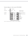
-
 1
1
-
 2
2
-
 3
3
-
 4
4
-
 5
5
-
 6
6
-
 7
7
-
 8
8
-
 9
9
-
 10
10
-
 11
11
-
 12
12
-
 13
13
-
 14
14
-
 15
15
-
 16
16
-
 17
17
-
 18
18
-
 19
19
-
 20
20
-
 21
21
-
 22
22
-
 23
23
-
 24
24
-
 25
25
-
 26
26
-
 27
27
-
 28
28


Minebea Intec YSB02 Digital Input/Output Module for RS-485 Interface Guide d'installation
- Taper
- Guide d'installation
Documents connexes
-
 Minebea Intec Combics CAIXS2 antidéflagrant pour l’utilisation dans des atmosphères explosibles Le manuel du propriétaire
-
 Minebea Intec YDO07-X Datenausgang für Combics-Ex Le manuel du propriétaire
-
 Minebea Intec Combics 3 Dosage Basic (option H3) et dosage Extra (option H4) Modèles CAISL3 | CAIS3 | CAW3P | CAW3S Dosage automatique d’un composant Le manuel du propriétaire
-
 Minebea Intec Combics CAISL1, CAISL2, CAIS1, CAIS2 Indicateurs Le manuel du propriétaire
-
 Minebea Intec Combics 3 CAISL3 | CAIS3 Indicateurs Le manuel du propriétaire
-
 Minebea Intec Relaisbox YSB01 Le manuel du propriétaire
-
 Minebea Intec Combics Balances complètes, CAW2P | CAW2S Le manuel du propriétaire
-
 Minebea Intec YDO01M-232 (A11), YDO01M-232CLK (A31), YDO01M-232CO (A1), YDO01M-485 (A2 | A3), YDA01M-20MA (A9), YDO01M-IO (A5), YDO01M-EN (B9) Data Output Port for Midrics® COM1 and UniCOM Interfaces Le manuel du propriétaire
-
 Minebea Intec Plates-formes de pesée modèle ISXBBS pour les atmosphères explosibles Le manuel du propriétaire
-
 Minebea Intec Data Output Port for Combics UniCOM Interface YDO01, YDA01 Le manuel du propriétaire


