SportsArt DF200 Le manuel du propriétaire
- Catégorie
- Fitness, gymnastique
- Taper
- Le manuel du propriétaire

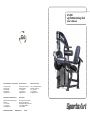
DF-200
Leg Extension/Leg Curl
Owner’s Manual
ISO 9001/14001 Certied GoSportsArt.com 2016.06
Sports Art Industrial Co., Ltd. (Headquarter)
#11, Gong Huan Road,
Tainan City, Taiwan
T: 886 6 3840888
F: 886 6 3840999
Sports Art America Inc.
19510 144th Ave. N.E., Suite A-1,
Woodinville, WA 98072
T: +1 425 4819479
F: +1 425 4888155
Sports Art Fitness UK Ltd.
Unit 2, 3 Charnwood Business Park,
North Road, Loughborough,
LE11 1LE, England
T: +44 1509 274440
Sports Art Europe, Middle East & Africa
Strada Cantonale 42, Ch-6534 San Vittore,
Switzerland
T: +41 91 8273908
F: +41 91 8273910
Sports Art China
Room 2202, BLDG. A, Huapu Garden,
Dongzhimen South Street, No. 9,
Dongcheng District Beijing, 100007 China
T: +86 10 84094122/84094123
F: +86 10 84094121

DF-200 OWNER’S MANUAL CONTENTS
1. INTRODUCTION ................................................................................ 2
2. SAFETY PRECAUTIONS .................................................................. 3
3. LIST OF PARTS ................................................................................. 4
4. ASSEMBLE THE PRODUCT ............................................................. 10
STEP 1 Cover Support Plate and the Connector Installation ................ 10
STEP 2 Weight Stack Installation .......................................................... 14
STEP 3 Apply the Weight Stack Sticker ................................................ 18
STEP 4 CAM Installation ....................................................................... 19
STEP 5 Cable Installation ..................................................................... 22
STEP 6 Floating Pulley Installation ....................................................... 26
STEP 7 Finger Guard Installation ......................................................... 27
STEP 8 Cylindrical Cushion Arm Installation ........................................ 28
STEP 9 Upper Cable Adjustment ......................................................... 29
STEP 10 Lower Cable Adjustment ....................................................... 30
STEP 11 Upper Cushion Arm Installation ............................................. 31
STEP 12 Seat Bottom and Seat Back Installation ................................ 32
STEP 13 Covers Installation ................................................................. 34
STEP 14 Storage Tray Installation ........................................................ 39
STEP 15 Secure the Product ................................................................ 40
STEP 16 Stack Fork Inspections .......................................................... 41
5. OPERATION INSTRUCTION ........................................................... 42
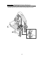
OPERATION Operating the Product .................................................... 42
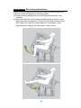
OPERATION Exercising Instructions ................................................... 46
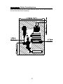
OPERATION Safety Operating Area ................................................... 47
6. MAINTENANCE ................................................................................ 48
MAINTENANCE Safety Precautions .................................................... 48
MAINTENANCE Guide Rod Cleaning and Lubricating ........................ 49
MAINTENANCE Schedule .................................................................... 50
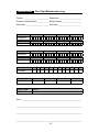
MAINTENANCE Task List .................................................................... 51
MAINTENANCE One-Year Maintenance Log ....................................... 52
7. CONSIGNES DE SÉCURITÉ IMPORTANTES ................................. 53

2
1. INTRODUCTION
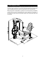
Congratulations on the purchase of a high quality SportsArt product, the DF-200 Leg
Extension / Leg Curl machine. Constructed of high quality materials and designed for
years of reliable performance, this product was made for full commercial use.
Before this product is assembled or operated, we recommend that you familiarize
yourself with this manual. Understanding the correct assembly and operation of
this product will help ensure that exercisers obtain their tness goals safely and
successfully.

3
2. SAFETY PRECAUTIONS
This product was designed and built for optimum safety. However certain precau-
tions apply during the use of this product. Please note the following safety precau-
tions:
• Please read the entire manual before assembly and operation. Make sure the
product is installed and operated as instructed in this manual.
• Assemble and operate the product on a solid, level surface. Do not use outdoors
or near water, including pools and saunas.
• Check the product before every use. Make sure all parts are assembled, and all
fasteners are tightened. Do not use the product if it is disassembled in any way.
• Wear proper workout clothing. Do not wear loose clothing. Do not wear shoes
with leather soles or high heels. Tie all long hair back. Do not go barefoot on this
product.
• Keep away from moving parts. Moving parts may or may not stop immediately if
an object becomes caught or impedes normal motion.
• Use this product only for its intended purpose as described in this manual.
• Be careful when mounting and dismounting the unit.
• Never operate this product if it has been damaged in any way. If it is not work-
ing properly, or has been dropped or damaged, contact a service technician for
repairs.
• Do not use accessories or parts that are not specifically recommended by the
manufacturer (SportsArt). Such parts might cause injuries or cause the unit to
fail and void the warranty. We will not be responsible for any safety issue that
arises due to the misuse of accessories or parts. At the same time, we will termi-
nate the warranty terms of this equipment.
• This product is not intended for use by persons (including children 12 or younger)
with reduced physical, sensory, or mental capabilities, or by people who are
otherwise deficient in product knowledge or experience. If such people use this
product, they should be given training and be supervised at all times by some-
one responsible for their safety.
• Children 12 or younger should be supervised to ensure that they do not play on
or near the product.
• The user weight limit for this product is 227 kg, 500 lb.
• Maintenance and repair must be performed by trained service personnel
only.
CAUTION: If you feel any pain or any abnormal sensations, STOP YOUR WORK-
OUT and consult your physician immediately. Work within your recommended ex-
ercise level. DO NOT work to exhaustion. Before beginning any exercise program,
you should consult with your doctor. It is recommended that you undergo a complete
physical examination.
*NOTE: Each machine provides a different resistance ratio of weight stack.

4
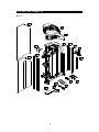
3. LIST OF PARTS
Box A

5
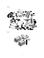
Box B
Box C

6
Box A - Main Frame Components
No. Name Qty. No. Name Qty.
A1
Weight stack top right
cover
1 A10 Bracket 4
A2
Weight stack top left
cover
1 A11 Cover 1
A3 Main frame 1 A12 Rear cover 1
A4 Cover support plate B-2 1 A13 Front cover 1
A5 Cover support plate B-1 1 A14 Cover support plate A 2
A6 Stack fork 1 A15 Floor xing bracket 1
A7 Weight stack rod 1 A16 U bracket 1
A8 Cover bracket 4 A17 Owner’s manual 1
A9 Bracket 2
Box B - User Frame Components
No. Name Qty. No. Name Qty.
A20 CAM 1 A30 Floating pulley 1
A21 Finger guard 1 A31 Connector A 1
A22 Stopper A 1 A32 Connector B 1
A23 Cylindrical cushion 1 A33 Connector C 1
A24 Upper cushion arm 1 A34 Ø50 Connecting board A 1
A25 Seat back 1 A35 Ø50 Connecting board 5
A26 Seat frame 1 A36 Hardware kit 1
A27 Storage tray 1 A37 Pulley 1
A28 Seat bottom 1 A38 Finger guard A 1
A29 Cylindrical cushion arm 1
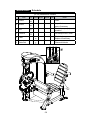
Box C - Weight Plates Components
No. Name Qty. No. Name Qty.
A40 5kg/11lb weight plate 19 A41 Weight plate sticker 1

7
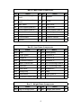
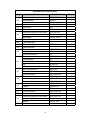
Components on the Product
No. Name Specication Notes
32 Upper stack carriage set
33
Hex head screw M8*P1.25*L65
Washer D17*d8.3*t2
PU tube ØD12*d8*L51
Nylon hex lock nut M8
34
Hex head screw M8*P1.25*L65
Washer D17*d8.3*t2
PU tube ØD12*d8*L82
Nylon hex lock nut M8
35 Guide rod
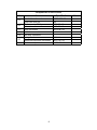
Components in the Hardware Kit
No. Name Qty. Specication Notes
15 Mushroom top inner hex screw 12 M6*P1.0*L12
16 Mushroom top Phillips screw 8 M5*L15
17 Screw socket 8 SGN-07
18 Mushroom top Phillips screw 10 M5*0.8*L8
19 Round sticker 1
20 Soft cap 1
21
Inner hex screw 2 M6*P1.0*L12
Bushing 2 D19*7.8
22 Front cover bracket 1
23 Phillips screw 6 M6*P1.0*L12
24
Flat washer 2 D27*d6.3*t3.0
Mushroom top inner hex screw 2 M5*L20
25
Hex head screw 12 M10*P1.5*L130
Spring washer 12 M10
Washer 24 D16*d10.2*t1.0
Nylon hex lock nut 12 M10
L-shaped Allen wrench 1 M4*L60mm
L-shaped Allen wrench 1 M5*L114mm*W24
L-shaped Allen wrench 1 M6*L120mm*W28
T-shaped Allen wrench 1 M4*L100
Double open end wrench 1 8mm*10mm
Screwdriver shank 1 Phillips and at
Double open end wrench 2 13*17

8
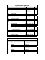
Components on the Product
No. Name Specication Notes
36
Inner hex screw M8*P1.25*L18
Spring washer M8*t2.0
Washer D17*d8*t1.5
37 Inner hex screw M8*P1.25*L20
38 Axle cover Ø65
39 Mushroom top inner hex screw M6*P1.0*L20
40
Mushroom top inner hex screw M6*P1.0*L12
Spring washer M6
Flat washer D20*d6.3*t1.5
41 Pulley bracket
42 CAM stop plate
43 Mushroom top inner hex screw M6*P1.0*L10
44 Cable set block
45
Mushroom top inner hex screw M6*P1.0*L20
Spring washer M6
Nylon hex lock nut M6
46
Mushroom top inner hex screw M6*P1.0*L12
Spring washer M6
Flat washer D20*d6.3*t1.5
Axle ØD15*L24
Pulley ØD126*20
47
Nylon hex lock nut M8*P1.25
Flat washer D20*d8*t2.0
Inner hex screw M8*P1.25*L25
48
Nylon hex lock nut M6*P1.0*6
Flat washer D16*d6.3*t2
Mushroom top inner hex screw M6*P1.0*L20
49
Inner hex screw M8*P1.25*L15
Washer D28*d8.5*t2
50 Axle cover Ø50
51 Inner hex screw M8*P1.25*L30
52 Inner hex screw M8*P1.25*L20
53
Mushroom top inner hex screw M8*P1.25*L25
Spring washer M8
Washer D22*d8.2*t2
54 Seat back plate

9
Components on the Product
No. Name Specication Notes
55
Beveled head inner hex screw M8*P1.25*L20
Nylon hex lock nut M8
56
Mushroom top Phillips screw M5*0.8*L15
Flat washer D13*d6*t1.0
57 Inner hex screw M5*P0.8*L10
58 Set fork
59 Bolt assy. crossover
60
Spring washer M6*t1.5
Mushroom top inner hex screw M6*P1.0*L10
61 Mushroom top inner hex screw M6*P1.0*L12

10
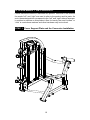
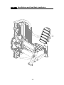
4. ASSEMBLE THE PRODUCT
Follow instructions below to assemble this product. Note that in this manual
the words “left” and “right” are used to refer to the product and its parts. As
such, these designations correspond to the “left” and “right” sides of a person
in position to exercise on this product. Also, for brevity, the word “screws” or
“nuts” is used where washers and other hardware may be involved.
STEP 1 Cover Support Plate and the Connector Installation

11
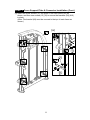
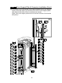
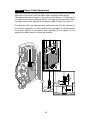
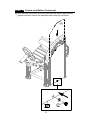
STEP 1 Cover Support Plate & Connector Installation (Cont.)
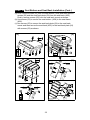
(a) Insert the screw sockets (17) into place in the main frame (A3) as
shown, and then use screws (15) (16) to secure the brackets (A9) (A10)
in place.
(Note: The bracket (A9) must be secured to the top of main frame as
shown.)
(a)

12
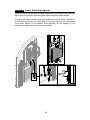
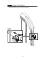
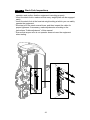
STEP 1 Cover Support Plate & Connector Installation (Cont.)
(b) Use screws (18) to secure the cover support plates (A14) to the straight
frame of the main frame (A3) and then secure the cover support plates
(A4) (A5) on both sides of the curved frame as shown.
(Note: The cover support plates must be secured outside of the bracket
(A9) (A10).)
(b)

13
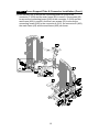
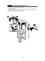
STEP 1 Cover Support Plate & Connector Installation (Cont.)
(c) Use screws (25) to secure the connecting board A (A34) to the
connector C (A33) and the main frame (A3) in area A. Use screws (25)
to secure the connecting board (A35) to the connector C (A33) and the
seat frame (A26) in area B. And then use screws (25) to secure the
connecting board (A35) to the connector A (A31), the connector B (A32),
the main frame (A3) and the seat frame (A26) as shown.
A
B

14
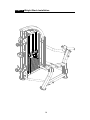
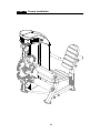
STEP 2 Weight Stack Installation

15
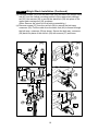
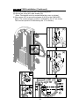
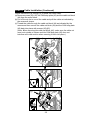
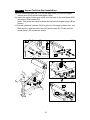
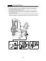
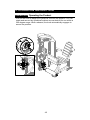
STEP 2 Weight Stack Installation (Continued)
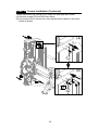
Follow instructions (a) through (g) to install the weight stack.
(a) Hold the upper stack carriage set (32), and then cut the zip tie. Gently
lower the upper stack carriage set (32) into place as shown.
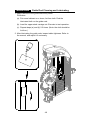
(b) Remove screws (33) (34). Set the guide rod (35) downward into place
as shown.
(c) Tilt the guide rod (35) backward and then lift the upper stack carriage
set (32) off the guide rods as shown. Carefully set the upper stack
carriage set (32) aside.
(a)
(b)
(c)

16
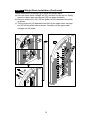
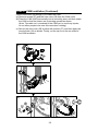
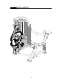
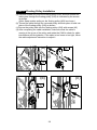
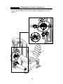
STEP 2 Weight Stack Installation (Continued)
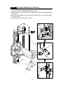
(d) Remove screws (36) from the stack fork (A6) and insert the weight stack
rod (A7) into the central mounting position of the upper stack carriage
set (32). Use screws (36) to secure the stack fork (A6) into place of the
upper stack carriage set (32) as shown.
(Note: Remove the stack fork first before assembling.)
(e) Remove screws (57) from the set fork (58) to remove the bolt assy.
crossover (59). Pull the cable from the stack fork (A6) to thread through
the bolt assy. crossover (59) as shown. Secure the bolt assy. crossover
(59) back into place of the set fork (58) with screws (57) as shown.
(d)
(e)

17
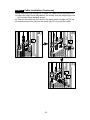
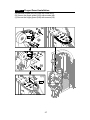
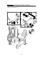
STEP 2 Weight Stack Installation (Continued)
(f) Insert and lower the (5 kg/11lb) weight plate (A40) into place on the
guide rods (35) one at a time. Once complete, slide down the upper
stack carriage set (32) on top of the weight stack.
(Note: The convex side of weight plate should face up and the stack fork
(A6) points toward the front.)
*If there is an optional (7.5kg/16.5lb) weight plate installed, insert the
optional weight plates before the (5 kg/11lb) weight plates (A40).
(g) Tilt the guide rods (35) back into place and then lift them up to their
mounting position, and then secure the assembly with screws (33) (34).
(g)
(f)

18
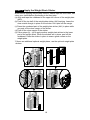
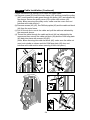
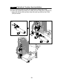
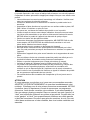
STEP 3 Apply the Weight Stack Sticker
Note: Before applying weight plate stickers, please wipe the area clean, and
clean your hands before proceeding to the next step.
(a) Align and tape the cardboard to the upper left corner of the weight plate
(A40).
(b) Peel off the top half of the weight plate sticker (A41) backing. Leave the
clear outside margin in place on the sticker. Don’t peel off the margin.
(c) Press the numbered part of the weight plate sticker (A41) in place while
you peel off the clear margin of the sticker.
(d) Peel off the clear margin of the sticker.
(e) Follow steps (b) ~ (d) to apply another weight plate sticker to the lower
part of the weight stack. When the stickers are in place, peel off the
cardboard. Press the sticker in place to ensure good contact on the
weight plate.
*If there are additional optional weight plates, use the optional weight plate
stickers.
(b)
(a)
(c)
(d)
(e)

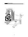
19
STEP 4 CAM Installation
La page est en cours de chargement...
La page est en cours de chargement...
La page est en cours de chargement...
La page est en cours de chargement...
La page est en cours de chargement...
La page est en cours de chargement...
La page est en cours de chargement...
La page est en cours de chargement...
La page est en cours de chargement...
La page est en cours de chargement...
La page est en cours de chargement...
La page est en cours de chargement...
La page est en cours de chargement...
La page est en cours de chargement...
La page est en cours de chargement...
La page est en cours de chargement...
La page est en cours de chargement...
La page est en cours de chargement...
La page est en cours de chargement...
La page est en cours de chargement...
La page est en cours de chargement...
La page est en cours de chargement...
La page est en cours de chargement...
La page est en cours de chargement...
La page est en cours de chargement...
La page est en cours de chargement...
La page est en cours de chargement...
La page est en cours de chargement...
La page est en cours de chargement...
La page est en cours de chargement...
La page est en cours de chargement...
La page est en cours de chargement...
La page est en cours de chargement...
La page est en cours de chargement...
La page est en cours de chargement...
La page est en cours de chargement...
-
 1
1
-
 2
2
-
 3
3
-
 4
4
-
 5
5
-
 6
6
-
 7
7
-
 8
8
-
 9
9
-
 10
10
-
 11
11
-
 12
12
-
 13
13
-
 14
14
-
 15
15
-
 16
16
-
 17
17
-
 18
18
-
 19
19
-
 20
20
-
 21
21
-
 22
22
-
 23
23
-
 24
24
-
 25
25
-
 26
26
-
 27
27
-
 28
28
-
 29
29
-
 30
30
-
 31
31
-
 32
32
-
 33
33
-
 34
34
-
 35
35
-
 36
36
-
 37
37
-
 38
38
-
 39
39
-
 40
40
-
 41
41
-
 42
42
-
 43
43
-
 44
44
-
 45
45
-
 46
46
-
 47
47
-
 48
48
-
 49
49
-
 50
50
-
 51
51
-
 52
52
-
 53
53
-
 54
54
-
 55
55
-
 56
56


SportsArt DF200 Le manuel du propriétaire
- Catégorie
- Fitness, gymnastique
- Taper
- Le manuel du propriétaire
dans d''autres langues
- English: SportsArt DF200 Owner's manual
Documents connexes
-
SportsArt DF205 Le manuel du propriétaire
-
SportsArt DF204 Le manuel du propriétaire
-
-
-
SportsArt DF201 Le manuel du propriétaire
-
-
-
-
-