Baxtran ARX Manuel utilisateur
- Catégorie
- Balances personnelles
- Taper
- Manuel utilisateur
Ce manuel convient également à

V.2.7
21/07/2023
EN - ES - FR - PT - IT - DE
PALLET TRUCK WITH SCALE
TRANSPALETA PESADORA
TRANSPALETTE PESEUR
PALETES DE PESAGEM
PESA PER TRANSPALLET
WIEGEHUBWAAGEN
ARX
USER’S MANUAL | MANUAL DE USUARIO | MANUEL D’UTILISATION |
MANUAL DE USUARIO | MANUALE D’USO | BENUTZERHANDBUCH
El fabricante se reserva el derecho de modificar sin previo aviso las características de sus productos para introducir mejoras técnicas o cumplir con nuevas regulaciones oficiales./Le
constructeur se réserve le droit de modifier les caractéristiques de ses produits en vue d’y apporter des améliorations techniques ou de respecter de nouvelles réglamentations./The
manufacturer reserves the right to modify the specifications of its products in order to make technical improvements or comply with new regulations./ Il produttore si riserva il diritto di modificare
le caratteristiche dei prodotti senza preavviso per introdurre miglioramenti tecnici o per conformarsi a nuove normative ufficiali.
trade mark propiety of | marca propiedad de | est une marque de | marca de propriedade de |
marchio di proprietà di:
Pol. Empordà Internacional C/ Molló, 3
17469 VILAMALLA - (Girona) SPAIN
T. (34) 972 527 212

ARX
2
FR - CONTENU
0. Information préalable 34
1. Introduction 37
2. Fiche technque 38
3. Fonction principale 38
4. Dimension boundry 38
5. Introduction au panel 39
6. Paramétrage 41
RÉGLAGE ENTRÉE 41
F1 RÉGLAGE DES PARAMÉTERS DE LA BALANCE 41
F2 APPLIQUER LES PARAMÈTRES DE FONCTION 42
F3 RÉGLAGE DU PARAMÈTRE POUR ÉCONOMIE D’ÉNERGIE 44
F4 RÉGLAGE SERIAL-PORT 44
F5 MAINTENANCE ET SERVICE 44
7. Description des fonctions 45
8. Prompt Message of instrument 47
EN - CONTENTS
0. Previous information 5
1. Introduction 8
2. Technical indicators 9
3. Main function 9
4. Boundary dimension 9
5. Introduction to panel 10
6. Parameter setting 12
SETTING ENTRY 12
F1 PARAMETER SETTING OF SCALE 12
F2 APPLICATION FUNCTION SETTING 13
F3 ENERGY-SAVING PARAMETER SETTING 14
F4 PRINTER CONFIGURATION (NON MODIFY) 15
F5 MAINTENANCE AND SERVICE 15
7. Function description 15
8. Prompt Message of instrument 17
ES - ÍNDICE
0. Información previa 19
1. Introducción 22
2. Indicadores técnicos 23
3. Función principal 23
4. Dimensión de frontera 23
5. Introducción al panel 24
6. Configuración de parámetros 26
CONFIGURACIÓN ENTRADA 26
F1 CONFIGURACIÓN PARÁMETROS DE LA BÁSCULA 26
F2 APLICAR FUNCIÓN CONFIGURACIÓN 27
F3 CONFIGURACIÓN DE PARÁMETROS DE AHORRO DE ENERGÍA 28
F4 CONFIGURACIÓN IMPRESORA (NO MODIFICAR) 29
F5 MANTENIMIENTO Y SERVICIO 29
7. Descripción de Funciones 30
8. Impulsar Mensaje de Instrumento 32

ARX
3
PT - ÍNDICE
0. Informação prévia 49
1. Introduçao 52
2. Indicadores técnicos 53
3. Funções principais 53
4. Dimension boundry 53
5. Introdução no painel 54
6. Definindo parâmetros 56
ENTRAR CONFIGURAÇÃO 56
F1 PARÂMETRO CONFIGURAÇAO DA BALANÇA 56
F2 APLICAR FUNÇÃO CONFIGURAÇÃO 57
F3 CONFIGURAÇAO DE PARÂMETROS DE POUPANÇA DE ENERGIA 59
F4 CONFIGURAÇAO IMPRESSORA (NÂO MODIFICAR) 59
F5 MANUTENÇÃO E SERVIÇO 59
7. Função de descrição 60
8. Solicitar mensagem de dispositivo 62
IT - ÍNDICE
0. Informazioni preliminari 64
1. Introduzione 67
2. Indicatori tecnici 68
3. Funzione principale 68
4. Dimensione della macchina 68
5. Introduzione al pannello 69
6. Configurazione parametri 71
CONFIGURAZIONE ENTRATA 71
F1 CONFIGURAZIONE DEI PARAMETRI DELLA BILANCIA 71
F2 APPLICARE FUNZIONE DI CONFIGURAZIONE 72
F3 CONFIGURAZIONE DEI PARAMETRI DI RISPARMIO ENERGETICO 73
F4 CONFIGURAZIONE DELLA STAMPANTE (NON MODIFICARE) 74
F5 MANUTENZIONE E SERVIZIO 74
7. Descrizione delle funzioni 74
8. Messaggio dello strumento di alimentazione 76
DE - INDEX
0. Vorab-informationen 78
1. Einführung 81
2. Technische Daten 81
3. Funktionen 82
4. Abmessungen 82
5. Display und Tasten 83
6. Einstellungen 85
MENÜ AUFRUFEN 85
F1 EINSTELLUNGEN DER WAAGE 85
F2 EINSTELLUNGEN DER FUNKTIONEN 86
F3 EEINSTELLUNGEN ZUM STROMSPARMODUS 87
F4 DRUCKER EINSTELLUNGEN 88
F5 WARTUNG UND SERVICE 88
7. Funktionsbeschreibung 88
8. Fehlermeldungen 90

ENENUSER’S MANUAL ARX
4
!
!
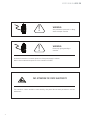
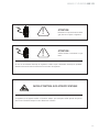
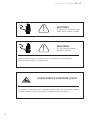
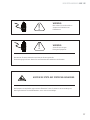
WARNING:
Ask professional personnel to debug,
detect and repair controller.
WARNING:
Please keep good grounding of
controller.
PAY ATTENTION TO STATIC ELECTRICITY
In electrical connection of controller, please cut off the power supply in advance.
Wait for 30 seconds between power-on of the controller for 2 times.
The controller is a device sensitive to static electricity, thus please take anti-static precautions in use and
maintenance.

5
ENENUSER’S MANUAL ARX
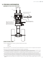
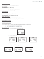
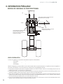
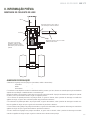
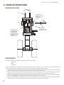
0. PREVIOUS INFORMATION
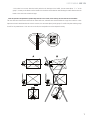
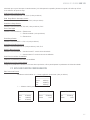
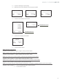
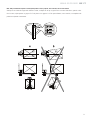
ASSEMBLY OF THE SET OF THE HELM
With the Axis and chain
installed, it can be used after
pressing the bar down and
pulling out the thrust plunger
After the axis pierces, the
chain pass through this hole
After the axis pierces, knock
05 mm pin into pinhole
bar
chain
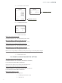
LEVER OF REGULATION
The lever of regulation has three positions (ascending, medium and descending)
ascending --
media --
descending --
When the hand pallet is not, the helm must be placed in medium position. The position of the lever of regulation has been adjusted
in factory, if it is necessary to change it, the customer must follow the following steps:
1. If you push the lever downwards in medium position, the forklifts will go upwards, then the user must turn around the unload
screw following the movement of the hands of the clock, the forklifts will not rise when you press the lever.
2. If you push the lever downwards in medium position, the forklifts will go downwards, and then the user must turn the unloading
screw following the movement of the hands of the clock until the forklifts do not go downwards when you press the lever.
3. If the user has the lever of regulation in a descending position, the forklifts do not go downwards, then the user must turn the un-
loading screw following the movement of the hands of the clock until the forklifts go downwards when the user presses the lever.
4. If the user has the lever of regulation in an ascending position, the forklifts will not go upwards. The user must turn the unloading
screw following a direction opposite to the movement of hands of the clock until the forklifts go upwards with the lever in this
position.

ENENUSER’S MANUAL ARX
6
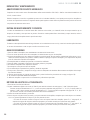
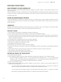
REPARATION AND MAINTENANCE
HYDRAULIC OIL SUPPLY
Check the oil every six months. We recommend you to use the hydraulic oil: ISO VG32, a 400C its kinematics viscosity is of 32
cSt, the total 0.3 liters.
Due to transport or reversal, it is possible that some air gets into the hydraulic bomb, and this fact can cause a problem in the
forklifts. Perhaps they are not going to rise when they are in an ascending position.
The following method can help the user to avoid the problem: The user must move the lever from the ascending position to the
ascending position more than once, repeating the process.
ROUTINES OF MAINTENANCE AND REPARATION
The routine of maintenance is essential. The user must center this revision in the wheels and the mandrel, retire all the strange
bodies and objects which are placed on the wheels, and also avoid that the wheels get poked.
When the wheels are free of dirtiness and strange objects, the user must retire the load and place the forklifts downwards until they
reach their lowest position.
LUBRICANT
When the lever of regulation is in factory, we apply different long life lubricants both to the bearings and the axis, the user only need
to apply the lubricant once a month or every time that the user proceeds to do an in-depth revision.
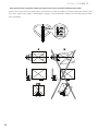
SECURITY GUIDE
1. Before proceeding to use the hand pallet, the user must read the following guide of instructions carefully.
2. The user must bear in mind that before pulling of the hand pallet , it is necessary to rise the forklifts a little.
3. When the user pulls of the hand pallet, it is important to keep the lever in a medium position. In such way, it will be easier to move
the hand pallet and the bounces of the piston of the lever will be reduced. Moreover, it will also protect the seal of the liquid and
the components of the piston. All this is important because it helps the life and usefulness of the hand pallet.
4. The hand pallet must be used and handled by people who have the appropriate qualification on how to use it.
5. Before proceeding to use the hand pallet, the user must revise the wheels, the levers and the forklifts.
6. Don’t use the hand pallet on oblique surfaces.
7. Don’t put a person on the forklift.
8. It is recommended that the operator wears gloves and security footwear.
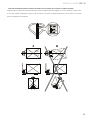
9. In the process of elevation and transport of load, all the workers which are near the hand pallet must keep themselves far from
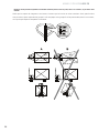
the forklifts, at least at a distance of 600 mm.
10. The user must pay a lot of attention in the way of charging the pallet and avoid the slope or deviation of the load. (see figure 2 B)
11. The user must not exceed the maximum capacity of the hand pallet.
12. The user must use the hand pallet with care in special circumstances and placements.
WAY OF ADJUSTING THE HAND PALLET
1. Disconnect the socket of the indicator.
2. Adjust the digital multimeter in the scale of “200 Ω” to measure the resistance of each group of “10 Ω”. Ways of adjustment:
Connect an end to the multimeter of d “E+” and then with the other end to check each group of “E +” A, B, C and D. Adjust
all the groups to “10 Ω”. Now connect an end of the multimeter to “E-“ and with the other end check every group of the “E-“
A, B, C and D. You must at least realize 8 measures and finally disconnect the multimeter.
3. Insert the socket to the indicator and connect it.
4. Place the weight in the frontal part, in the middle and in the back part of the forklifts, check that the value of the weight is the
same, if it is not so, you must adjust a little the groups C and D in the plate of the circuit:
- If the value is not correct when the load is placed in the frontal part of the forklift, the user must adjust “D +” of the
group D, following the direction of the hands of the clock if the variations are small and against the direction of the hands
of the clock if the variations are bigger.

7
ENENUSER’S MANUAL ARX
- If the value is not correct when the load is palced on the back part of the forklift, the user must adjust “C +” of the
group C, contrary to the direction of the hands of the clock dor small variations and following the same direction than the
hands of the clock if the variation is larger.
Note: this procedure of adjustment is possible only when the error is small, on the contrary, the user must not use this method.
The user must also check that the load cells are intact and loose, and make sure that the forklifts do not get into contact. It is also
important to bear in mind that when the value is not exact, the user must adjust just the groups C and D of the plate and the groups
A and B of the potentiometer . If the user do not do this, the hand pallet can not be adjusted correctly.

ENENUSER’S MANUAL ARX
8
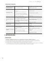
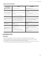
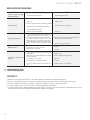
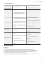
SOLVING PROBLEMS
MALFUNCTION CAUSE APPROACH
The fork cannot be raised to
its maximum height. The hydraulic oil used is not the correct one. Supply of oil.
The forklift does not raise.
Hydraulic oil needed.
Dirty oil.
Keep the bolts too near or the screws too tightened,
so that the valve remains open.
There is aire in the hydraulic bomb.
Supply of oil.
Change the oil.
Adjust the bolts and the screws.
Extract the aire.
The forklift can not go down-
wards.
The placement of the goods on an only side or the
overload, causes a damage on the pistons or the
body of the hydraulic bomb.
The forklifts has been raised during a period of time
too long, and this has caused that the oxidation of
the blocks of movement of the pistons.
The bolt and the screw are not placed in the correct
position.
Replace the pistons for a bigger ones.
Lower the forklift to a minimum position when it is
used and lubricate the rib.
Adjust the bolt or screw.
Spillage of oil. Ageing or flaws in the seals.
Some pieces are broken.
Update.
Update.
The valve of unload does not
work.
Due to the dirty oil the valve cannot be closed her-
metically.
A piece of the hydraulic system is damaged or
broken.
Air has mixed with oil.
Seal aged or damaged pieces.
The bolt or screws is not placed in its correct po-
sition.
Change the oil.
Revise and change the wasted pieces.
Extract the air.
Update.
Adjust the bolt or screw.
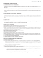
1. INTRODUCTION
CONDITIONS
1. Please keep the scale in a cool dry place. Do not store it at high temperature.
2. Do not allow any liquids to come into contact with the scale. If necessary wipe the scale with a dry soft cloth.
3. Avoid objects impacting with the scale. Do not drop loads onto the scale or subject the weighing pan to any strong shock loads.
4. The load placed on the weigh pan must not exceed the maximum weighing capacity of the scale.
5. If the scale is not going to be used for some time, please clean it and store it in a plastic bag in dry conditions. A desiccant sachet
may be included to prevent any moisture building up.

9
ENENUSER’S MANUAL ARX
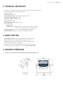
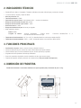
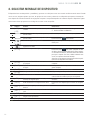
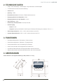
2. TECHNICAL INDICATORS
▪6-digit 1.2-inch LED display, 7 state indicator lamps. Long service life and shock resistance
▪7 function keys. Operation is simple and convenient
▪Protection level: IP5x
▪Excitation voltage: +5VDC
▪Load capacity of sensor: at most 4 350Ω simulation sensors
▪Input signal range of null point: 0-5mV
▪Input signal range of full scale: 1-10 mV
▪Inner resolution: 1 million
▪Weight upgrading rate: 40 times per second
▪Power supply mode
Battery: 6V4Ah
Battery Charger: voltage 100-240VAC Current 0.26A Frequency 50-60Hz.
// 7VAc 1A - + With LED indicator of the state of charge
▪Operating temperature: -10ºC to +40ºC, relative humidity is below 85 %
▪Storage temperature: -20ºC to +60ºC, relative humidity is below 85 %
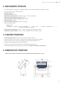
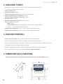
3. MAIN FUNCTION
▪Basic weighing function: resetting, removing the peel and clearing the peel
▪Weight detection function, counting function, animal scale function
▪Weight keeping function, weight accumulation function, percentage display
▪Set redundant backup function of parameters
▪Automatic screen protection and automatic shutdown energy-saving function
▪Rich printing formats and communication protocol. (Only for printer models)
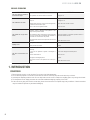
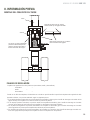
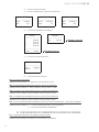
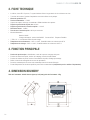
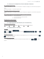
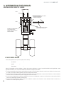
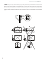
4. BOUNDRY DIMENSION
Instrument size: detailed in the following figure (mm); instrument weight: 1.5kg

ENENUSER’S MANUAL ARX
10
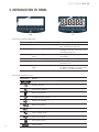
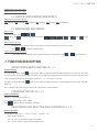
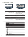
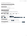
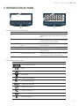
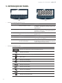
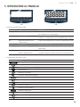
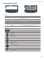
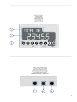
5. INTRODUCTION TO PANEL
LED LCD
• Introduction to indicator lamps (LED)
Identification Analysis Remark
~ Dynamic and static indication The lamp is on when scale is in dynamic
state, otherwise, the lamp is off.
→0← center indication The lamp is on when the absolute value
of weight on the scale is less than ±0.2d,
otherwise the lamp is off.
Net Identification of gorses weight and net
weight The lamp is on in net weight and off in
gross weight
kg Weight unit For indicating current unit
Hold Weight maintenance The lamp is on when the weight is locked,
otherwise it is off.
Ac Voltage indication of battery and power
supply The green lamp is on when the voltage of
the adapter and battery is normal, and the
red lamp is on in undervoltage state.
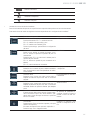
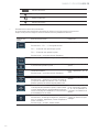
• Introduction to indications (LCD)
Identification Analysis
Sorting and weight check status indicator
Extension indicator
Counting scale indicator
Animal scale indicator
Accumulating scale indicator
Weighing info available
Weight hold indicator
Net weight indicator
Scale in dynamic status
Scale at zero indicator
Key pressed indicator
Battery indicator

11
ENENUSER’S MANUAL ARX
Weight unit
Counting scale unit
Weight % indicator
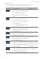
• Introduction to operation keys
Operationwithout special specification refers to short press on keys.
Each key takes the following functions according to the F mesure settings.
Key symbol Normal weighing state Set state
Weight maintenance key
Short press → F2.1 = 1, keep/cancel.
F2.1 = 2, switch between percentage and weight.
F2.1 = 5, switch between quantity and weight.
Long key → enter setting menu.
Return to the last menu.
Accumulation key
Short key → F2.1 = 4, include display weight in accu-
mulation value.
Long key → F2.1 = 3, select scale to sample target
weight.
F2.1 = 4, accumulate weight of scale display.
F2.1 = 5, count sampling of scale.
No definition.
Unit conversion key
Short key → in weighing state, switch weight unit. The
corresponding unit indication lamp is on.
Flicker bit is on the left.
Gross key
Short key → net weight turns to gross weight; induction
lamp of net weight “Net” is off.
Flicker bit is on the right.
Tare key
Short key → gross weight turns to net weight. Indication
lamp of net weight “Net” is on. Conduct skin removal
operation for multiple times.
Digit flicker position reduces.
Clearing key
Gross weight state resets weight. When the scale is in
net weight, dynamic state, saving state and out of reset-
ting range, clearing operation is invalid
In setting, digit of flicker posi-
tion increases. In adjustment
of display, accumulation is
cleared.
ON/OFF key
Short key → start up or print. (only for printer models)
Printing format refers to Appendix1.
Long key → shut down. Turn on/off
Confirm operation, to save
setting data.

ENENUSER’S MANUAL ARX
12
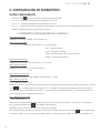
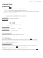
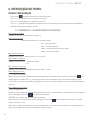
6. INTRODUCTION TO PANEL
SETTING ENTRY:
Press the button on the operating panel in the state of normal weighing.
If F1.14 = 0, you can set all the parameters within F1~F5.
If F1.14 = 1, you can only set all parameters within F2~F5.
If F1.14 = 1 and you need to set the parameters within F1 menu, you can press the calibration switch button until the F1 menu is
entered.
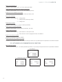
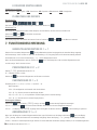
F1 PARAMETER SETTING OF SCALE
F1.1 Measuring Range
Selectable parameters: 3~200000 (default value: 6)
F1.2 Decimal Places
Selectable parameters: 0 ---- no decimal point
0.0 ---- 1 decimal place
0.00 ---- 2 decimal places
0.000 ---- 3 decimal places (default value)
0.0000 ---- 4 decimal places
F1.3 Number of Divisions
Selectable parameters: 1 (default value), 2, 5, 10, 20, 50
F1.4 Calibration Unit
Selectable parameters: 0 ---- kg (default value)
1 ---- lb
F1.5 Gravitational Acceleration
Selectable parameters: 9.70000~9.99999. Default value = 9.79455.
F1.6 Null-point Calibration
[E-SCL] Keeping empty the scale
Remove the weights on the weighing platform to guarantee the scale is in the empty state. Press the key and the meter will dis-
play [0 cal]. The displayed digits will reduce slowly until the meter displays [00 cal ]. In the end it will display [End] for one second,
which indicates the end of null-point calibration.
F1.7 Load-point Calibration
[LOAd] Loading weights
Load weights on the weighing platform to ensure that 10% of full-scale value ≤ weight of weights ≤ full-scale value, and then press
the key to start the next step.
[000000] Entering the same weight value as that of the loaded weights.
Entering the same weight value as that of the loaded weights, please press the key after the scale becomes stable, and the
meter will display [ ]. After that, the displayed digits will reduce slowly until the meter displays [ ]. In the end it will display [ ] for one
second, which indicates the end of null-point calibration.
F1.8 Automatic Null Tracking
Selectable parameters: OFF, 1 d, 2 d, 3 d (default value)
F1.9 Automatic Reset Range at Startup
Selectable parameters: OFF, 2 %, 10 %, 20 % (default value)

13
ENENUSER’S MANUAL ARX
F1.10 Button Reset Range
Selectable parameters: OFF, 2 %, 10 % (default value), 20 %
F1.11 Digital Filter
Selectable parameters: 0 ---- Mild Filtering
1 ---- Moderate Filtering (default value)
2 ---- Severe Filtering
F1.12 Steady Range
Selectable parameters: 1 d, 2 d, 3 d (default value)
F1.13 Overload Display Range
Selectable Parameters: 9d, 5% (default value), 10%, 20%
F1.14 F1 Menu Protection
Selectable Parameters: 0 ---- Enter F1 menu by keyboard operation
1 ---- Enter F1 menu by pressing the calibration button
F1.15 Steady-state filer choice
Set the parameters for the steady-filter.
F1.16 Restoring Factory Default
Set the parameters within F1~F4 as the defaults, which can’t impact the parameters of standard scale.
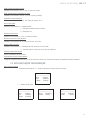
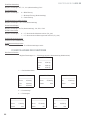
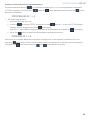
F2 APPLICATION FUNCTION SETTING
F2.1 Function Selection
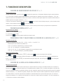
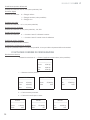
Selectable Parameters: 0 ---- Close the application functions (default value)
REPORT
---------------------------
Gross 0.200 Kg
Tare 0.000 Kg
Net 0.200 Kg
1 ---- Weight keeping function
REPORT
---------------------------
Gross 0.200 Kg
Tare 0.000 Kg
Net 0.200 Kg
REPORT
---------------------------
Gross 25.000 Kg
Status Hold
REPORT
---------------------------
Net 25.000 Kg
Status Hold
2 ---- Percentage display function
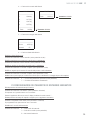
3 ---- Weight checking and sorting function
REPORT
---------------------------
Gross 1.980 Kg
State Less
REPORT
---------------------------
Gross 25.000 Kg
State OK
REPORT
---------------------------
Net 25.000 Kg
State Over

ENENUSER’S MANUAL ARX
14
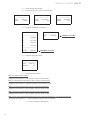
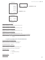
4 ---- Accumulative scale function
REPORT
---------------------------
1 0.200 kg
2 0.175 kg
3 0.347 kg
4 0.375 kg
---------------------------
Total: 1097Kg
REPORT
---------------------------
Total 1.097 Kg
5 ---- Counting scale function
REPORT
---------------------------
Gross 0.547 Kg
Amount 55
6 ---- Animal scale function
F2.2 Empty-scale threshold value
Selectable Parameters: 0~ full range (default value: 0.001)
F2.3 Target Weight for Weight Checking and Sorting
Selectable Parameters: 0~ full range (default value: 2.000)
F2.4 Positive Error for Weight Checking and Sorting
Selectable Parameters: 0~ full range (default value: 0.100)
F2.5 Negative Error for Weight Checking and Sorting
Selectable Parameters: 0~ full range (default value: 0.100)
F2.6 Access to Target Weight for Weight Checking and Sorting, and Counting Sample Weight
Selectable Parameters: 0 ---- Access to Platform Weighing (default value)
1 ---- Manual Input Access
F3 ENERGY-SAVING PARAMETER SETTING
F3.1 Time-out Screensaver Time Setting
Selectable Parameters: 0~ 99 minutes, (default value: 30 minutes)
If set to be 0, this function shall not be allowed.
During the screen protection, the display will randomly show “ ”.
F3.2 Energy-saving Time Setting for Auto Power-off
Settable Parameters: 0~250 minutes. (default value: 150 minutes)
If set to be 0, this function shall not be allowed.
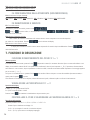
F3.3 Display Brightness Control
Selectable Parameters: 0---- low light level
1 ---- middle light level (default value)
2 ---- high light level
Parameter 4.2.3 in 1
Parameter 4.2.3 in 0

15
ENENUSER’S MANUAL ARX
F3.4 Real-time clock, date setting
F3.5 Real-time clock, time setting
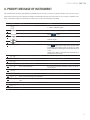
F4 PRINTER CONFIGURATION (NON MODIFY)
F4.2.4 Printing languages selection
CHI: CHINESE \ ENG: ENGLISH \ FRA: FRENCH \ ESP: SPANISH \ ITA: ITALIAN \ POR: PORTUGUESE
F5 MAINTENANCE AND SERVICE
F5.1 Key test
Instrument display¡, press , , ,
, [lb/kg] and in order, and the instrument displays , , , , and , press to quit
key test.
F5.2 Display screen test
All strokes of meter display will have self-inspection, to observe whether there is lacks of strokes.
Press or to quit test of display screen.
F5.3 Display current internal code
The display will show internal code of current instrument after smoothing. Press or to quit the interface.
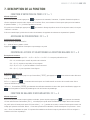
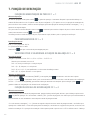
7. FUNCTION DESCRIPTION
WEIGHT MAINTENANCE FUNCTION F2.1 = 1
Operation method
In normal weighing state, press on the operation panel, the will instrument lock display weight of the current scale, and “Hold”
indication lamp is on. Only when weight setting value≥F2.2 is displayed, weight maintenance operation is effective. Otherwise, it will
return to weighing state after invalid operation information [--no--] is shown for a second.
If weight is in locked state, press again to cancel locking of weight and return to normal weighing state, and “Hold” indication
lamp is off.
If it is in weight locking state, refuse to remove skin, clear skin and setting operation.
PERCENTAGE DISPLAY F2.1 = 2
Display specification
Display [Pr 20.5], representing 20.5 %.
Pr = current actual weight / range ×100%.
Press to display switch in percentage and weight.
CHECK WEIGHT AND SELECTION SCALE FUNCTION F2.1 = 3
Function description
Set parameters such as F2.2 = A, F2.3 = B, F2.4 = C and F2.5 = D.
When display weight is X.
If X ≤ A, do not conduct check weight and selection.
If X < (B – D), it lacks of weight, and the display flickers.

ENENUSER’S MANUAL ARX
16
If (B – D) ≤ X ≤ (B – C), it is qualified and the display has normal display
If X > (B – C), it is overweight and the display flickers.
Acquisition of target value
Press long until the display shows [TARGET], and then press to show current target value and flicker.
If F2.6 = 0, press , the instrument will take the weight on current scale as the new target value and quit the setting interface.
If F2.6 = 1, the display shows [000000], to request manual change of target value. After change, press to save setting data
and quit setting interface.
FUNCTION OF ACCUMULATION SCALE F2.1 = 4
Operation method
In normal weighing state, when the scale is in , add weight to the scale and press on operation panel, if the display shows
[Add--] progress bar, it indicates that the current display weight is included accumulated value, and then it returns to normal weighing
state. If the display shows [--no--] for a second, and returns to the normal weighing state, it indicates operation is invalid. Reason:
1. Between two accumulation operations, the scale must have back-to- process, otherwise, accumulation is refused. 2. Accumulation
operation is effective only when display weight≥F2.2 is set. 3. The scale is in dynamic state.
Adjustment, clearing and printing of accumulated value
In normal weighing state, press on operation panel for more than 2 seconds, the display will show [Zero] for a second, and
then the display shows current total accumulated value [A 9.500] and flickers. To clear accumulated value, press [Pr 20.5], to make
flicker weight be 0. Press to print accumulated data. Press to quit the interface.
Attention: set whether to be over detailed data or accumulated data in F4.6.
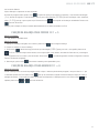
FUNCTION OF COUNTING SCALE F2.1 = 5
Instrument display
[c 128], showing current quantity.
Sampling method
1. Check whether the scale is in , if not, press for setting.
2. Place materials counted on the scale.
3. Press long until the display shows [SAMPLE], and then press . If F2.6 = 0, the display shows [PC5 00]. Input the
quantity counted just now, and press for confirmation. The instrument saves sampling data and quits the sampling interface.
If F2.6 = 1 (if this function is activated, you will have to indicate the unit weight, it would be easier without activating it), the display
shows [000000], input sample weight. Press , the instrument saves setting data and quits sampling setting interface.
4. In this function, press to display switch between quantity and weight.
FUNCTION OF ANIMAL SCALE F2.1 = 6
Operation method
In normal weighing state, place the animal on the weighing platform and its weight must be ≥threshold value set in F2.2. Press ,
instrument will collect data sampling. After sampling, the average value of sampling data will be locked, showing A X.XXX. Press
to print; press or to quit the interface.

17
ENENUSER’S MANUAL ARX
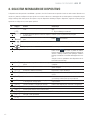
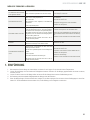
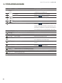
8. PROMPT MESSAGE OF INSTRUMENT
The instrument has extremely high stability and reliability, thus is not easy to have error in general situation. Once an error occurs,
please make clear the error first and observe whether the instrument still has error after power-on. Do not hurry to repair the scale
body or instrument. Repair the instrument according to error code of the instrument as possible.
Nº Symbol Analysis Remark
1[-EEE]
[ EEE]
Unable to reset after startup 1. Determine it is no-load state in startup;
2. Make calibration again.
2[]The weighed object is over full range for 9 days Reduce weight on weighing platform
3[]The weighed object is below 0 for 5 DAYS Press to reset
4[]
[ ]
Out of clearing range Check whether the weighing platform has weight.
Remove weight.
5Invalid operation
6[Err 03]EEPROM checksum and error Press reprint factory value. Start up again. If the
information occurs again, return to factory for repair.
Please calibrate the scale again if the situation does not
occur;
Attention: this place is provided with all parameters of
instruments of the factory.
7[Err 05]The calibration input weight is too small Input≥10 % weight of full range
8[Err 06]The weight in calibration is too light Load≥10% weight of full range
9[Err 07]The scale is dynamic in scale Inspect the scale body
10 [Err 08]Setting error of date and time Set according to specification of date and time
11 [Err 09]Error of AD initialization If the error occurs after restarting, return it to the fac-
tory for repair
12 [LOAd]In loading scale, it indicates to loading weight; Load weight according to requirements
13 [SEtUP]It has enters menu setting Pres [print] to continue setting.
14 [End ]End of point and loading point calibration
15 [Add-- ]Including current display weight in accumulated
value
16 [-OUER-]Accumulated weight overflows Clear accumulated weight in time.
17 [Ld--- ]Loading default value
18 [Print]Printing

ESESMANUAL DE USUARIO ARX
18
!
!
ADVERTENCIA:
Pedir ayuda a personal especializado
para depurar, detectar o reparar el re-
gulador.
ADVERTENCIA:
Por favor, proporcione una buena base
al controlador.
PRESTE ATENCIÓN A LA ELECTRICIDAD ESTÁTICA.
Cuando conecte eléctricamente el controlador, por favor corte primero la fuente de alimentación.
Espere durante 30 segundos cuando se encienda el controlador, 2 veces.
El controlador es un dispositivo sensitivo a la electricidad estática, por tanto, por favor, tome precauciones
antiestáticas cuando lo utilice y también durante su mantenimiento.

19
ESESMANUAL DE USUARIO ARX
0. INFORMACIÓN PREVIA
MONTAJE DEL CONJUNTO DEL TIMON
Con el eje y la cadena instalados,
puede ser utilizado después de
presionar la barra hacia abajo y
tirando del émbolo de empuje
Después de perforar el eje, la cadena
pasa a través de este agujero
Después de perforar el eje, golpear
05mm el alfiler por el agujero del alfiler
barra
cadena
PALANCA DE REGULACIÓN
La palanca de regulación tiene tres posiciones (ascendente, media y descendiente)
ascendente --
media --
descendiente --
Cuando no se utilice la transpaleta, el timón debe ser colocado en posición media. La posición de la palanca de regulación ha sido
ajustada en fábrica, si se precisa cambiarla, seguir los siguientes pasos:
1. Si se empuja la palanca hacía abajo en posición media, las horquillas se elevan, girar el tornillo de descarga en el sentido de las
agujas del reloj, las horquillas no se elevarán cuando se presione la palanca.
2. Si se empuja la palanca hacía abajo en posición media, las horquillas descenderán, girar el tornillo de descarga en el sentido
contrario de las agujas del reloj hasta que las horquillas no desciendan al presionar la palanca.
3. Con la palanca de regulación en posición descendente, las horquillas no descienden, girar el tornillo de descarga en el sentido
de las agujas del reloj hasta que las horquillas desciendan al presionar la palanca.
4. Con la palanca de regulación en posición ascendiente, las horquillas no se elevarán, girar el tornillo de descarga en sentido con-
trario a las agujas del reloj hasta que las horquillas se eleven con la palanca en esta posición.

ESESMANUAL DE USUARIO ARX
20
REPARACIÓN Y MANTENIMIENTO
ABASTECIMIENTO DE ACEITE HIDRÁULICO
Comprobar el aceite cada 6 meses. Recomendamos utilizar aceite hidráulico: ISO VG32, a 400C su viscosidad cinemática es de
32 cSt, el total 0.3 litros.
Debido al transporte o inversión, es probable que entre aire en la bomba hidráulica, lo cual puede provocar que las horquillas no
se eleven en la posición de ascenso. El siguiente método puede ayudar a evitarlo: Mover la palanca desde la posición de ascenso
a la posición de descenso varias veces.
RUTINA DE MANTENIMIENTO Y REVISIÓN
La rutina de mantenimiento es esencial. Usted debe centrarse en las ruedas y en el mandril, retirar los cuerpos extraños que se
ubiquen en las ruedas y evitar que éstas se pinchen. Cuando las ruedas queden libres de suciedad y cuerpos extraños, retirar la
carga y descender las horquillas hasta la posición más baja.
LUBRICANTES
En fábrica se han aplicado lubricantes de larga vida tanto en los rodamientos como en el eje, usted solo necesita aplicar lubricante
en un mes de intermitente o cada vez que se realice una revisión a fondo.
GUIA DE SEGURIDAD
1. Antes de utilizar la transpaleta, leer detenidamente este manual de instrucciones.
2. Tener en cuenta que antes de tirar de la transpaleta, se deberá levantar un poco las horquillas.
3. Al tirar de la transpaleta, por favor, mantener la palanca en posición media. De esta manera, resultará más fácil de mover y se re-
ducirán los rebotes del pistón de la palanca. Además, también se protegerá el precinto del líquido y los componentes del pistón,
todo ello, extiende la vida útil de la transpaleta.
4. El transpalet debe ser utilizado por personal con formación cualificada.
5. Antes de utilizar el transpalet, inspeccionar las ruedas, palancas y horquillas.
6. No utilizar la transpaleta sobre superficies oblicuas.
7. No transportar a una persona sobre la horquilla.
8. Se recomienda que el operador lleve guantes y calzado de seguridad.
9. En el proceso de elevación y transporte de carga, todos los trabajadores de alrededor deben mantenerse alejados de las horqui-
llas al menos 600 mm.
10. Prestar mucha atención en el modo de cargar el palet y evitar la inclinación y desviación de la carga (ver figura 2 B).
11. No exceder la capacidad maxima del transpalet.
12. Utilizar el transpalet con precaución en circunstancias y ubicaciones especiales.
MÉTODO DE AJUSTE DE LA TRANSPALETA
1. Desconectar el enchufe del indicador.
2. Ajustar el multímetro digital en la escala de “200 Ω” para medir la resistencia de cada grupo a “10 Ω”. Método de ajuste:
Conectar una punta del multímetro a “E+” y con la otra punta comprobar cada grupo del “E +” A, B, C y D ajustar todos los
grupos a “10 Ω”. Ahora conectar una punta del multímetro a “E-“ y con la otra punta comprobar cada grupo del “E-“ A, B, C
y D. Al menos efectuar ocho medidas y finalmente desconectar el multímetro.
3. Insertar el enchufe del indicador y conectarlo.
4. Colocar el peso en la parte frontal, en medio y en la parte trasera de las horquillas, comprobar que el valor del peso es el mismo,
si no lo es, ajustar ligeramente los Grupos C y D de la placa de circuito:
- Si el valor es incorrecto cuando la carga se coloca en la parte frontal de la horquilla, ajustar “D +” del grupo D, en
sentido a las agujas del reloj para variaciones pequeñas y en sentido contrario para variaciones más grandes.
- Si el valor es incorrecto cuando la carga se coloca en la parte trasera de la horquilla, ajustar “C +” del grupo C, en
sentido a las agujas del reloj para variaciones pequeñas y en sentido contrario para variaciones más grandes.
La page est en cours de chargement...
La page est en cours de chargement...
La page est en cours de chargement...
La page est en cours de chargement...
La page est en cours de chargement...
La page est en cours de chargement...
La page est en cours de chargement...
La page est en cours de chargement...
La page est en cours de chargement...
La page est en cours de chargement...
La page est en cours de chargement...
La page est en cours de chargement...
La page est en cours de chargement...
La page est en cours de chargement...
La page est en cours de chargement...
La page est en cours de chargement...
La page est en cours de chargement...
La page est en cours de chargement...
La page est en cours de chargement...
La page est en cours de chargement...
La page est en cours de chargement...
La page est en cours de chargement...
La page est en cours de chargement...
La page est en cours de chargement...
La page est en cours de chargement...
La page est en cours de chargement...
La page est en cours de chargement...
La page est en cours de chargement...
La page est en cours de chargement...
La page est en cours de chargement...
La page est en cours de chargement...
La page est en cours de chargement...
La page est en cours de chargement...
La page est en cours de chargement...
La page est en cours de chargement...
La page est en cours de chargement...
La page est en cours de chargement...
La page est en cours de chargement...
La page est en cours de chargement...
La page est en cours de chargement...
La page est en cours de chargement...
La page est en cours de chargement...
La page est en cours de chargement...
La page est en cours de chargement...
La page est en cours de chargement...
La page est en cours de chargement...
La page est en cours de chargement...
La page est en cours de chargement...
La page est en cours de chargement...
La page est en cours de chargement...
La page est en cours de chargement...
La page est en cours de chargement...
La page est en cours de chargement...
La page est en cours de chargement...
La page est en cours de chargement...
La page est en cours de chargement...
La page est en cours de chargement...
La page est en cours de chargement...
La page est en cours de chargement...
La page est en cours de chargement...
La page est en cours de chargement...
La page est en cours de chargement...
La page est en cours de chargement...
La page est en cours de chargement...
La page est en cours de chargement...
La page est en cours de chargement...
La page est en cours de chargement...
La page est en cours de chargement...
La page est en cours de chargement...
La page est en cours de chargement...
La page est en cours de chargement...
La page est en cours de chargement...
-
 1
1
-
 2
2
-
 3
3
-
 4
4
-
 5
5
-
 6
6
-
 7
7
-
 8
8
-
 9
9
-
 10
10
-
 11
11
-
 12
12
-
 13
13
-
 14
14
-
 15
15
-
 16
16
-
 17
17
-
 18
18
-
 19
19
-
 20
20
-
 21
21
-
 22
22
-
 23
23
-
 24
24
-
 25
25
-
 26
26
-
 27
27
-
 28
28
-
 29
29
-
 30
30
-
 31
31
-
 32
32
-
 33
33
-
 34
34
-
 35
35
-
 36
36
-
 37
37
-
 38
38
-
 39
39
-
 40
40
-
 41
41
-
 42
42
-
 43
43
-
 44
44
-
 45
45
-
 46
46
-
 47
47
-
 48
48
-
 49
49
-
 50
50
-
 51
51
-
 52
52
-
 53
53
-
 54
54
-
 55
55
-
 56
56
-
 57
57
-
 58
58
-
 59
59
-
 60
60
-
 61
61
-
 62
62
-
 63
63
-
 64
64
-
 65
65
-
 66
66
-
 67
67
-
 68
68
-
 69
69
-
 70
70
-
 71
71
-
 72
72
-
 73
73
-
 74
74
-
 75
75
-
 76
76
-
 77
77
-
 78
78
-
 79
79
-
 80
80
-
 81
81
-
 82
82
-
 83
83
-
 84
84
-
 85
85
-
 86
86
-
 87
87
-
 88
88
-
 89
89
-
 90
90
-
 91
91
-
 92
92


Baxtran ARX Manuel utilisateur
- Catégorie
- Balances personnelles
- Taper
- Manuel utilisateur
- Ce manuel convient également à
dans d''autres langues
- italiano: Baxtran ARX Manuale utente
- español: Baxtran ARX Manual de usuario
- Deutsch: Baxtran ARX Benutzerhandbuch
- português: Baxtran ARX Manual do usuário
Documents connexes
Autres documents
-
HAEGER KS-DIG.008A Manuel utilisateur
-
 PRONAR DIGIDEVICE Le manuel du propriétaire
-
Mettler Toledo IND221 / IN226 Manuel utilisateur
-
Marantec CS 320 Le manuel du propriétaire
-
-
-
Hobart HT Scale Guide de démarrage rapide
-
Adam Equipment EBL Manuel utilisateur
-
-
Yamaha CLP-50 Le manuel du propriétaire
