Simer 2806E-01 Le manuel du propriétaire
- Catégorie
- Pompes à eau
- Taper
- Le manuel du propriétaire
Ce manuel convient également à

©2005 1000000171 (Rev. 7/26/06)
OWNER’S MANUAL
Convertible Deep Well Jet Pumps
and Tank System
NOTICE D’UTILISATION
Pompes à éjecteur
transformables pour puits
profond et système de réservoir
sous pression
MANUAL DEL USUARIO
Bombas de chorro
convertibles para pozos
profundos y Sistema de Tanque
Installation/Operation/Parts
For further operating, installation, or
maintenance assistance:
Call 1-800-365-6832
English . . . . . . . . . . . . . . Pages 2-14
Installation/Fonctionnement/Pièces
Pour plus de renseignements
concernant l’utilisation,
l’installation ou l’entretien,
Composer le
1 (800) 365-6832
Français . . . . . . . . . . . Pages 15-27
Instalación/Operación/Piezas
Para mayor información sobre el
funcionamiento, instalación o
mantenimiento de la bomba:
Llame al 1-800-365-6832
Español . . . . . . . . . . .Paginas 28-40
4025 0801
Mod. Nos. 2805E-01, 2806E-01,
2810E-01, 2815E-01
293 Wright St., Delavan, WI 53115
Phone:
1-800-468-7867
1-800-546-7867
Fax:
1-800-390-5351
Web Site:
http://www.simerpump.com

Safety 2
For parts or assistance, call Simer Customer Service at 1-800-468-7867 / 1-800-546-7867
READ AND FOLLOW
SAFETY INSTRUCTIONS!
This is the safety alert symbol. When you see this
symbol on your pump or in this manual, look for
one of the following signal words and be alert to the
potential for personal injury:
warns about hazards that will cause serious
personal injury, death or major property damage if
ignored.
warns about hazards that can cause serious
personal injury, death or major property damage if
ignored.
warns about hazards that will or can cause
minor personal injury or property damage if ignored.
The label NOTICE indicates special instructions which
are important but not related to hazards.
Carefully read and follow all safety instructions in this
manual and on pump.
Keep safety labels in good condition.
Replace missing or damaged safety labels.
ELECTRICAL SAFETY
Hazardous voltage. Can shock, burn or
kill. Capacitor voltage may be hazardous. To discharge
the motor capacitor, hold the insulated handle screw-
driver BY THE HANDLE and short the capacitor termi-
nals together. Do not touch the metal screwdriver blade
or capacitor terminals. If in doubt, consult a qualified
electrician.
GENERAL SAFETY
Burn hazard. Do not touch an operating
motor. Modern motors are designed to operate at high
temperatures. To avoid burns when servicing pump,
allow it to cool for 20 minutes after shut-down before
handling.
Do not allow the pump or any system component to
freeze. To do so will void the warranty.
Pump water only with this pump.
Periodically inspect the pump and system components.
Wear safety glasses at all times when working on pumps.
Keep the work area clean, uncluttered and properly light-
ed; store properly all unused tools and equipment.
Keep visitors at a safe distance from the work areas.
Hazardouse pressure. Risk of explosion.
Pump body may explode if used as a booster pump
unless a relief valve capable of passing the full pump
flow at 75 psi is installed.
WARNING
Hazardous pressure!
Install pressure relief
valve in discharge pipe.
Release all pressure on
system before working on
any component.
WARNING
Hazardous voltage.
Can shock, burn, or
cause death.
Ground pump before
connecting to power
supply. Disconnect power
before working on pump,
motor or tank.
Wire motor for correct
voltage. See “Electrical”
section of this manual and
motor nameplate.
Ground motor before
connecting to power
supply.
Meet National Electri-
cal Code, Canadian
Electrical Code, and local
codes for all wiring.
Follow wiring instruc-
tions in this manual
when connecting motor to
power lines.

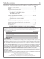
Table of Contents 3
Thank you for purchasing a top quality, factory tested pump.
Page
General Safety .....................................................................................................2
Warranty..............................................................................................................3
Replacing an Existing Pump.................................................................................4
New Shallow Well Installation..........................................................................5,6
• Well Point (Driven Point)
• Cased Well, 2" or larger casing
• Installation for Surface Water
New Deep Well Installation..............................................................................6,7
• 4" or Larger Well
• 2" Well
• Pre-charged Tank Connection
• Standard Tank Connection
Electrical...........................................................................................................8,9
Preparing To Start The Pump – Deep Well .........................................................10
Preparing To Start The Pump – Shallow Well .....................................................11
Troubleshooting..................................................................................................12
Repair Parts ..................................................................................................13,14
ATTACH ORIGINAL RECEIPT HERE FOR WARRANTY CONSIDERATION.
SIMER warrants to the original consumer purchaser (“Purchaser”) of its products that they are free from defects in material or workmanship.
If within twelve (12) months from the date of the original consumer purchase any such product shall prove to be defective, it shall be repaired or
replaced at SIMER’s option, subject to the terms and conditions set forth below. Your original receipt of purchase is required to determine warranty
eligibility.
Exceptions to the Twelve (12) Month Warranty
Product/Model No. Warranty Period
M40P, M80,BW85P, CM10, CMK 90 days
2330, 2300, 2955, 2957, A5500 2 Years
4" Submersible Well Pumps, 3984, 3983, 2975PC, 2958, 3075SS 3 Years
Pre-Charge Water System Tank, 3986, 3985, 2956, 2960 5 Years
3988, 3995, 3997, 3963 Lifetime
General Terms and Conditions
Purchaser must pay all labor and shipping charges necessary to replace product covered by this warranty. This warranty shall not apply to
acts of God, nor shall it apply to products which, in the sole judgement of SIMER, have been subject to negligence, abuse, accident, misap-
plication, tampering, alteration; nor due to improper installation, operation, maintenance or storage; nor to other than normal application, use
or service, including but not limited to, operational failures caused by corrosion, rust or other foreign materials in the system, or operation at
pressures in excess of recommended maximums.
Requests for service under this warranty shall be made by returning the defective product to the Retail outlet or to SIMER as soon as possi-
ble after the discovery of any alleged defect. SIMER will subsequently take corrective action as promptly as reasonably possible.No
requests for service under this warranty will be accepted if received more than 30 days after the term of the warranty.
This warranty sets forth SIMER’s sole obligation and purchaser’s exclusive remedy for defective products.
SIMER SHALL NOT BE LIABLE FOR ANY CONSEQUENTIAL, INCIDENTAL, OR CONTINGENT DAMAGES WHATSOEVER.
THE FOREGOING WARRANTIES ARE EXCLUSIVE AND IN LIEU OF ALL OTHER EXPRESS WARRANTIES. IMPLIED WARRANTIES,
INCLUDING BUT NOT LIMITED TO THE IMPLIED WARRANTIES OF MERCHANTABILITY AND FITNESS FOR A PARTICULAR PUR-
POSE, SHALL NOT EXTEND BEYOND THE DURATION OF THE APPLICABLE EXPRESS WARRANTIES PROVIDED HEREIN.
Some states do not allow the exclusion or limitation of incidental or consequential damages or limitations on how long an implied warranty
lasts, so the above limitations or exclusions may not apply to you. This warranty gives you specific legal rights and you may also have other
rights which vary from state to state.
SIMER • 293 Wright Street • Delavan, WI U.S.A. 53115
Phone: 1-800-468-7867/1-800-546-7867 • Fax: 1-800-390-5351
E-Mail: inf[email protected] • Web Site: http://www.simerpumps.com

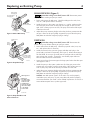
Replacing an Existing Pump 4
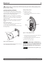
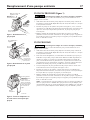
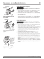
SHALLOW WELL (Figure 1)
Hazardous voltage. Can shock, burn or kill. Disconnect power
to pump before working on pump or motor.
1. Drain and remove the old pump. Check the old pipes for scale, lime,
rust, etc., and replace them if necessary.
2. Install the pump in the system (see Figures 4, 5, and 6). Make sure that
all of the pipe joints in the suction pipe are air-tight as well as water
tight. If the suction pipe can suck air, the pump will not be able to pull
water from the well.
3. Adjust the pump mounting height so that the plumbing connections do
not put a strain on the pump body. Support the pipe so that the pump
body does not take the weight of piping or fittings.
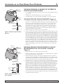
DEEP WELL
Hazardous voltage. Can shock, burn or kill. Disconnect the
power to the pump before working on pump or motor.
1. Drain and remove the old pump. Check the pipes for scale, lime, rust,
etc., and replace them if necessary.
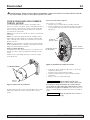
2. Install the control valve, pressure gauge, and deep well plug in the
pump body (purchase kit separately; see Figure 2). When connecting to
the well head, be sure you go small port to small port (drive) and large
port to large port (suction). If necessary, use flexible pipes and twist
them to make the correct connections.
3. Simer pumps have the suction pipe (the larger port) below the drive port
(see Figures 2 and 3).
4. Install the pump in the system. Make sure all of the pipe joints in the
suction pipe are air-tight as well as water tight. If the suction pipe can
suck air, the pump will not be able to pull water from the well.
5. Adjust the pump mounting height so that the plumbing connections do
not put a strain on the pump body. Support the pipe so that the pump
body does not take the weight of piping or fittings.
NOTICE: Your old injector system (in the well) may not be properly
matched to your new pump. If your pump does not perform properly,
we recommend that you install a Simer MDWE Injector Kit (4" well) or a
Simer MDWA Injector Kit (2" packer-type well).
For parts or assistance, call Simer Customer Service at 1-800-468-7867 / 1-800-546-7867
Control Valve
Port plugged
Pressure Gauge
Port plugged
Drive Pipe
Port plugged
Shallow Well
Injector Installed
4026 0801
To Household
From Well
The Drive Pipe
sends the water
down the well
and
drives
the
water up through
the Suction Pipe
to the Pump
Suction Port.
1799 0497 SIM
Discharge Port
Drive Port
Suction Port
4032 0801
Install Control
Valve
Install
Pressure
Gauge
Drive Pipe
To Well
Installed
Remove Shallow Well
Injector and Install
Deep Well Plug
To Household
From Well
Figure1: Shallow Well Setup
Figure 3: Deep Well Drive and
Suction Functions
Figure 2: Deep Well Setup

New Shallow Well Installation 5
SHALLOW WELL JET PUMP INSTALLATIONS
• Have a vertical depth between the pump and the water being pumped
of 25’ or less.
• Have one pipe from the well to the pump case.
• Can be installed in a bored or drilled well, or in a driven well.
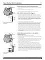
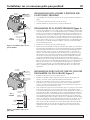
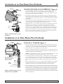
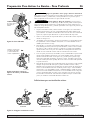
WELL POINT INSTALLATION (Figure 4)
1. Drive the well, using “drive couplings” and a “drive cap”. “Drive fit-
tings” are threaded all the way through and allow the pipe ends to butt
against each other so that the driving force of the maul is carried by the
pipe and not by the threads. The ordinary fittings found in hardware
stores are not threaded all the way through the fitting and can collapse
under impact. “Drive fittings” are also smoother than standard plumbing
fittings, making ground penetration easier.
2. Mount the pump as close to the well as possible.
3. Use the fewest possible fittings (especially elbows) when connecting the
pipe from the well point to the pump suction port. The suction pipe
should be at least as large as the suction port on the pump (include a
check valve). Support the pipe so that there are no dips or sags in the
pipe, so it doesn’t strain the pump body, and so that it slopes slightly
upward from the well to the pump (high spots can cause air pockets
which can air lock the pump). Seal the suction pipe joints with teflon
tape. Joints must be air- and water-tight. If the suction pipe can suck air,
the pump cannot pull water from the well. If one well point does not
supply enough water, consider connecting two or three well points to
one suction pipe.
CASED WELL INSTALLATION, 2" OR LARGER
CASING (Figure 5)
1. Mount the pump as close to the well as possible.
2. Assemble the foot valve, strainer, and well pipe. Make sure that the foot
valve works freely.
3. Lower the pipe into the well until the strainer is five feet above the bot-
tom of the well. It should also be at least 10 feet below the well’s water
level while the pump is running in order to prevent the pump from
sucking air. Install a sanitary well seal.
4. Install a priming tee, priming plug, and suction pipe to the pump.
Connect the pipe from the well to the pump suction port, using the
fewest possible fittings (especially elbows) as fittings increase friction in
the pipe. The suction pipe should be at least as large as the suction port
on the pump. Use teflon tape on threaded pipe joints. Joints must be air-
and water-tight. If the suction pipe can suck air, the pump cannot pull
water from the well. Support the pipe so that there are no dips or sags in
the pipe, so it doesn’t strain the pump body, and so that it slopes slightly
upward from the well to the pump (high spots can cause air pockets
which can air lock the pump).
For parts or assistance, call Simer Customer Service at 1-800-468-7867 / 1-800-546-7867
To Household
Water System
Not
to
Scale
Check
Valve
Relief
Valve
2097 0497 SIM
Drive
Coupling
Drive
Point
Drive point below
water level
Priming
Tee and
Plug
To Ho usehold
Water System
Not
to
Scal
e
Check
Valve
Relief
Valve
4033 0801
Suction Pipe
From Well
Priming
Tee and
Plug
Well
Casing
Foot
Valve
Sanitary
Well Seal
Strainer
5-10'
At least
10'
Figure 5:Typical Cased Well
Installation
Figure 4:Typical Well-Point
Installation

New Shallow Well Installation 6
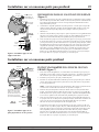
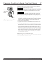
INSTALLATION FOR SURFACE WATER (Figure 6)
1. The pump should be installed as close to the water as possible, with the
fewest possible fittings (especially elbows) in the suction pipe. The suc-
tion pipe should be at least as large as the suction port on the pump.
2. Assemble a foot valve and suction pipe. Make sure that the foot valve
works freely. Use Teflon tape
TM
. Protect the foot valve assembly from
fish, trash, etc, by installing a screen around it.
3. Lower the pipe into the water until the strainer is five feet above the bot-
tom. It should also be at least 10 feet below the water level in order to
prevent the pump from sucking air.
4. Install a priming tee, priming plug, and suction pipe to the pump.
Support the pipe so that there are no dips or sags in the pipe, so it does-
n’t strain the pump body, and so that it slopes slightly upward from the
well to the pump (high spots can cause air pockets which can air lock
the pump). Seal the suction pipe joints with teflon tape. Joints must be
air and water tight. If the suction pipe can suck air, the pump cannot
pull water from the well.
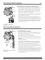
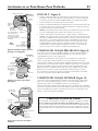
4" OR LARGER WELL (Figure 7)
1. Install the control valve, the pressure gauge and the deep well injector
plug in the pump body. See Figure 2. Purchase Model MDWC Deep
Well Conversion Kit to obtain these parts.
2. Mount the pump as close to the well as possible.
3. Install a flexible pipe between the well head and the pump so the con-
nection will be correct. Connect small port to small port and large port
to large port.
NOTICE: Simer jet pumps have the suction port (the larger port) below
the drive port. See Figure 3.
4. Connect both the suction and drive pipes to the ejector piping and
lower the ejector into the well until it is five feet from the bottom. It
should also be at least 10 feet below the well’s water level while the
pump is running in order to prevent the pump from sucking air.
5. Install a sanitary well seal and connect the ejector piping to the pump.
Use steel nipples through the well seal with flexible poly pipe to avoid
crushing the plastic pipe when tightening the seal.
6. Support the pipe so that there are no dips or sags in the pipe, so it does-
n’t strain the pump body, and so that it slopes slightly upward from the
well to the pump (high spots can cause air pockets which can air lock
the pump). Seal the suction pipe joints with teflon tape. Joints must be
air- and water-tight. If the suction pipe can suck air, the pump cannot
pull water from the well.
For parts or assistance, call Simer Customer Service at 1-800-468-7867 / 1-800-546-7867
To Household
Water System
Not
to
Scale
Check
Valve
Relief
Valve
4034 0801
Suction Pipe
From Well
Priming
Tee and
Plug
Foot
Valve
Screen
10'
Min.
5–10'
To Household
Water System
Not
to
Scale
Relief
Valve
4035 0801
Suction Pipe
From Well
If well head and pump
ports don't match, twist
reinforced flexible pipe
to make connections.
Well
Head
Venturi
Nozzle
Ejector
Foot Valve
Strainer
Drive Pipe
To Well
Figure 7:Typical 2” and 4” Deep Well
Installation
Figure 6:Typical Open Water
Installation
New Deep Well Installation

New Deep Well Installation 7
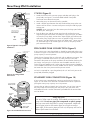
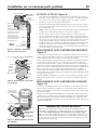
2" WELL (Figure 8)
1. Install the control valve, pressure gauge, and deep well plug in the
pump body. See Figure 2. Purchase Model MDWC Deep Well
Conversion Kit to obtain these parts.
2. Mount the pump as close to the well as possible.
3. Install a flexible pipe between the well head and the pump so the con-
nection will be correct. Connect small port to small port and large port
to large port.
NOTICE: Simer jet pumps have the suction port (the larger port) below
the drive port. See Figure 3.
4. Run the drive pipe and the suction pipe from the well to the pump.
Support the pipe so that there are no dips or sags in the pipe, so it does-
n’t strain the pump body, and so that it slopes slightly upward from the
well to the pump (high spots can cause air pockets which can air lock
the pump). Seal the suction pipe joints with Teflon tape
TM
. Joints must be
air- and water-tight. If the suction pipe can suck air, the pump cannot
pull water from the well.
PRE-CHARGE TANK CONNECTION (Figure 9)
If your system uses a pre-charged tank, it should be connected to the pump
as shown in Figure 9. The relief valve must be capable of passing the entire
pump capacity at 100 PSI pressure.
Check the pre-charge of the air in the tank with an ordinary tire gauge. The
pre-charge is measured
when there is no water pressure in the tank.
Disconnect the power to the pump and drain the tank before checking the
pre-charge. Your pump has a 20/40 PSI switch (Models 2805/6/10E) or a
30/50 PSI switch (Model 2815E), so the tank pre-charge pressure should be
18 PSI (Models 2805/6/10E) or 28 PSI (Model 2815E). That is, it should be 2
PSI lower than the cut-in pressure of the pressure switch.
NO AVC is required for a pre-charged tank; the 1/4” NPT AVC port on the
pump body should be plugged.
STANDARD TANK CONNECTION (Figure 10)
If your system uses a standard tank, connect it to the pump as shown in
Figure 10. The relief valve used with a standard tank must be capable of
passing the entire pump capacity at 75 PSI pressure.
Connect the Air Volume Control (AVC) tube to the 1/4" NPT AVC port on
the pump body. Run the tubing from the pump’s AVC port to the AVC
mounted on the tank. See the instructions provided with the tank and the
AVC for details.
For parts or assistance, call Simer Customer Service at 1-800-468-7867 / 1-800-546-7867
To the Household
Water System
Relief Valve
To
Waste
Pressure
Switch
2110 0497 SIM
Suction Pipe
From
the Well
Plugged
AVC
Port
Drive Pipe
To
the Well
To Household
Water System
Pressure
Switch
Suction Pipe
From Well
Air Volume
Control
Air Volume
Control Tube
Relief
Valve
Drive Pipe To Well
2
Figure 9: Pre-charged Tank
Connections
To Household
Water System
Not
to
Scale
Relief Valve
4035 0801
Suction Pipe
From Well
If well head and pump
ports don't match, twist
reinforced flexible pipe
to make connections.
Drive Pipe
To Well
Well Head
41
JET NO.
J32P-
24
Well Casing
serves as
Drive Pipe
Suction Pipe
Venturi
Nozzle
Ejector
Leather
Cup Seals
4036 0801
Figure 8:Typical 2” Deep Well
Installation
Figure 10: Standard Tank Connections
Sealing Pipe Joints
Use only Teflon tape for making all threaded connections to the
pump itself. Do not use pipe joint compounds on plastic pumps:
they can react with the plastic in pump components. Make sure
that all pipe joints in the suction pipe are air tight as well as
water tight.
If the suction pipe can suck air, the pump will not be
able to pull water from the well.

Electrical 8
MOTOR SWITCH SETTINGS
Dual-voltage motors (motors that can operate at either
115 or 230 volts), are set at the factory to 230 volts. Do
not change motor voltage setting if line voltage is 230
volts, or if you have a single voltage motor.
NOTE: Never wire a 115 volt motor to a 230 volt line.
NOTE: Wire TEFC motors according to wiring diagram in
junction box on motor. Be sure motor is connected for
correct line voltage.
NOTE: Wire 3-Phase motors according to wiring diagram
on motor. Be sure motor is connected for correct line
voltage.
Remove Motor End Cover
If you have a dual-voltage motor, and will connect it to
115 volts, follow the procedure below.
You will need to remove the motor end cover to change
the voltage setting.
Your motor terminal board (located under the motor end
cover) should look like the one below.
Dial Type Voltage Selector
To change to 115 volts:
1. Make sure power is off.
2. Turn the dial counter-clockwise until 115 shows in
the dial window.
3. Attach the power lead wires to the power lead termi-
nals. Make sure the wires are secure.
4. Attach the ground wire to the green ground screw
5. Reinstall the Motor end cover
Go to Wiring Connections below.
Hazardous voltage. Can shock, burn, or
kill. Connect ground wire before connecting power sup-
ply wires. Use the wire size (including the ground wire)
specified in the wiring chart. Connect the pump to its
own dedicated branch circuit with no other appliances
on it.
Explosion hazard. Do not ground to a gas
supply line.
For parts or assistance, call Simer Customer Service at 1-800-468-7867 / 1-800-546-7867
Figure 11: Removing End Cover
Motor
End Cover
End Cover Screws
Figure 12: Voltage Adjustment Dial
Voltage
Change Dial
Ground
Screw
Power Lead
Terminals
Hazardous voltage. Can shock, burn or kill. Disconnect the power before working on pump, motor,
pressure switch, or wiring.

Electrical 9
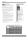
WIRING CONNECTIONS
Fire hazard. Incorrect voltage can cause a
fire or seriously damage the motor and voids the warran-
ty. The supply voltage must be within ±10% of the motor
nameplate voltage.
NOTICE: Dual-voltage motors are factory wired for 230
volts. If necessary, reconnect the motor for 115 volts, as
shown. Do not alter the wiring in single voltage motors.
Install, ground, wire, and maintain your pump in compli-
ance with the National Electrical Code (NEC) or the
Canadian Electrical Code (CEC), as applicable, and with
all local codes and ordinances that apply. Consult your
local building inspector for code information.
Connection Procedure:
1. Connect the ground wire first as shown in Figure 13.
The ground wire must be a solid copper wire at least
as large as the power supply wires.
2. There must be a solid metal connection between the
pressure switch and the motor for motor grounding
protection. If the pressure switch is not connected to
the motor, connect the green ground screw in the
switch to the green ground screw under the motor
end cover. Use a solid copper wire at least as large as
the power supply wires.
3. Connect the ground wire to a grounded lead in a ser-
vice panel, to a metal underground water pipe, to a
metal well casing at least ten feet (3M) long, or to a
ground electrode provided by the power company or
the hydro authority.
4. Connect the power supply wires to the pressure
switch as shown in Figure 13.
For parts or assistance, call Simer Customer Service at 1-800-468-7867 / 1-800-546-7867
Figure 13: Pressure Switch
Clamp the power cable
to prevent strain
on the terminal screws.
Connect the green
(or bare copper)
ground wire to the
green ground screw.
Motor wires connect here.
3187 0704
Power supply wires connect here.
230 Volt: Connect 2 hot wires
(black and red) here and cap
the white (neutral) wire. It
does not matter which wire
goes to which screw.
115 Volt: Connect one hot wire
(black or red) to one of these
screws (it doesn't matter which
one). Connect the white
(neutral) wire to the other screw.
Cap any remaining black or
red wires.
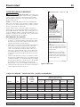
Wiring Chart – Recommended Wire and Fuse Sizes
Branch Distance in Feet (Meters);
Max Fuse Wire Size AWG (mm
2
)
Load Rating 0-100 101-200 201-300 301-400 401-500
Model HP Amps Amps (0-30) (31-61) (62-91) (92-122) (123-152)
115 Volts:
2805E-01 1/2 9.9 15 14(2) 12(3) 10(5.5) 8(8.4) 8(8.4)
2806E-01 1/2 9.9 20 12(3) 10(5.5) 8(8.4) 6(14) 6(14)
2810E-01 3/4 12.4 20 12(3) 10(5.5) 8(8.4) 6(14) 6(14)
2815E-01 1 14.8 20 12(3) 8(8.4) 6(14) 6(14) 4(21)
230 Volts:
2806E-01 1/2 4.95 15 14(2) 14(2) 14(2) 12(3) 12(3)
2810E-01 3/4 6.2 15 14(2) 14(2) 14(2) 12(3) 12(3)
2815E-01 1 7.4 15 14(2) 14(2) 14(2) 12(3) 10(5.5)

2117 0497 SIM
Remove the
control valve.
Fill the pump
and piping.
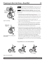
Preparing to Start the Pump – Deep Well 10
Burn hazard. Never the run pump dry. Running the pump with-
out water may cause pump to overheat, damaging seal and possibly caus-
ing burns to persons handling pump. Fill pump with water before starting.
Hazardous pressure. Risk of explosion. Never run the pump
against a closed discharge. To do so can boil water inside pump, causing
hazardous pressure in unit, risk of explosion and possibly scalding persons
handling pump.
1. Remove the control valve and fill the pump (see Figure 14). Fill all pip-
ing between the pump and the well, and make sure that all
piping in the well is full. If you have also installed a priming tee in the
suction piping, remove the plug from the tee and fill the suction piping.
2. Replace the fill plugs and the control valve completely (see Figure 15).
3. Power on! Start the pump and watch the pressure gauge. The
pressure should build rapidly to 40 PSI (Models (2805/6/10E) or 50 PSI
(Model 2815E), as the pump primes.
4. After 2 or 3 minutes, the gauge should show pressure. If not, stop the
pump, remove the fill plugs, reopen the control valve, and refill the
pump and piping. You may have to repeat this two or three times in
order to get all the trapped air out of the piping. Don’t forget to close
the control valve each time before you start the pump.
5. When the pressure has built up and stabilized at about 40 PSI (Models
(2805/6/10E) or 50 PSI (Model 2815E), slowly open the control valve
(see Figure 14) and let the pressure drop until the pressure gauge needle
starts to flutter. When the needle flutters, close the valve just enough to
stop the flutter. Your pump is now operating at its most efficient point.
6. After the pump has built up pressure in the system and shut off, check
the pressure switch operation by opening a faucet or two and running
enough water out to bleed off the pressure until the pump starts. The
pump should start when the pressure drops to 20 PSI (Models
(2805/6/10E) or 30 PSI (Model 2815E) and stop when the pressure
reaches 40 PSI (Models (2805/6/10E) or 50 PSI (Model 2815E). Run the
pump through one or two complete cycles to verify the correct opera-
tion. This will also help clean the system of dirt and scale dislodged dur-
ing installation.
Congratulations on a successful installation.
For parts or assistance, call Simer Customer Service at 1-800-468-7867 / 1-800-546-7867
Figure 15: Replace the Fill Plugs and
Control Valve
Figure 16: Set Control Valve
C-Close Control Valve until
Pressure Stabilizes
2146 0497 SIM
A-Open Control Valve
B-Watch for Pressure
Gauge to Flutter
Figure 14: Fill Pump
Replace all of the
fill plugs and close
the Control Valve
completely.
2120 0497 SIM

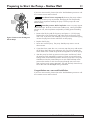
Preparing to Start the Pump – Shallow Well 11
If you were unsuccessful, please refer to the Troubleshooting section or call
our customer service technical staff.
Burn hazard. Never run pump dry. Running the pump without
water may cause the pump to overheat, damaging the seal and possibly
causing burns to persons handling the pump. Fill the pump with water
before starting.
Hazardous pressure. Risk of explosion. Never run pump against
closed discharge. To do so can boil water inside pump, causing hazardous
pressure in unit, risk of explosion and possibly scalding persons handling
pump.
1. Remove the fill plug and fill the pump (see Figure 17). Fill all piping
between the pump and the well, and make sure that all piping in the
well is full. If you have also installed a priming tee in the suction piping,
remove the plug from the tee and fill the suction piping.
2. Replace the fill plug.
3. Power on! Start the pump. The pump should pump water in two or
three minutes.
4. If you don’t have water after 2 or 3 minutes, stop the pump and remove
the fill plugs. Refill the pump and piping. You may have to repeat this
two or three times in order to get all of the trapped air out of the piping.
5. After the pump has built up pressure in the system and shut off, check
the pressure switch operation by opening a faucet or two and running
enough water out to bleed off pressure until the pump starts. The pump
should start when the pressure drops to 30 PSI and should stop when
pressure the reaches 50 PSI. Run the pump through one or two com-
plete cycles to verify correct operation. This will also help clean the sys-
tem of dirt and scale dislodged during installation.
Congratulations on a successful installation.
If you were unsuccessful, please refer to the Troubleshooting section or call
our customer service technical staff.
For parts or assistance, call Simer Customer Service at 1-800-468-7867 / 1-800-546-7867
2117 0497 SIM SW
Remove the
fill plug and
fill the pump
and piping.
Figure 17: Remove the Fill Plug and
Fill the Pump

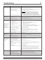
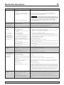
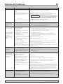
SYMPTOM POSSIBLE CAUSE(S) CORRECTIVE ACTION
Motor will not run Disconnect switch is off Be sure switch is on
Fuse is blown or circuit breaker tripped Replace fuse or reset circuit breaker
Starting switch is defective DISCONNECT POWER; Replace starting switch
Wires at motor are loose, Refer to instructions on wiring (Pages 8 and 9). DISCONNECT POWER;
disconnected, or wired incorrectly check and tighten all wiring.
Capacitor voltage may be hazardous. To discharge
capacitor, hold insulated handle screwdriver BY THE HANDLE and
short capacitor terminals together. Do not touch metal screwdriver
blade or capacitor terminals. If in doubt, consult a qualified electrician.
Pressure switch contacts are dirty DISCONNECT POWER and file contacts with emery board or nail file.
Motor runs hot and Motor is wired incorrectly Refer to instructions on wiring
overload kicks off
Voltage is too low Check with power company. Install heavier wiring if wire size is too small
(See Electrical / Wiring Chart).
Pump cycles too frequently See section below on too frequent cycling
Motor runs but no Pump in new installation did In new installation:
water is delivered* not pick up prime through:
1. Improper priming 1. Re-prime according to instructions
2. Air leaks 2. Check all connections on suction line, AVC and ejector
3. Leaking foot valve or check valve 3. Replace foot valve or check valve
Pump has lost prime through: In installation already in use:
1. Air leaks 1. Check all connections on suction line and shaft seal
2. Water level below suction pipe inlet 2. Lower suction line into water and re-prime. If receding water level
in well exceeds suction lift, a deep well pump is needed.
Foot valve or strainer is plugged Clean foot valve or strainer
Ejector or impeller is plugged Clean ejector or impeller
Check valve or foot valve is stuck shut Replace check valve or foot valve
Pipes are frozen Thaw pipes. Bury pipes below frost line. Heat pit or pump house.
Foot valve and/or strainer are Raise foot valve and/or strainer above bottom of water source.
buried in sand or mud Clean foot valve and strainer.
Water level is too low for shallow well A deep well jet package may be needed (over 25 ft. to water) to
setup to deliver water deliver water
Pump does not Water level in deep well is lower than Replace nozzle and venturi with correct combination for the well; lower
deliver water to full estimated the ejector to correct level in the well
capacity
Steel piping (if used) is corroded or Replace with plastic pipe where possible, otherwise with new steel pipe
limed, causing excess friction
Piping is too small in size Use larger piping
Pump delivers water but
Pressure switch is out of adjustment or DISCONNECT POWER; adjust or replace pressure switch
does not shut off or contacts are welded together
pump cycles too
Faucets have been left open Close faucets
frequently
Venturi, nozzle or impeller is clogged Clean venturi, nozzle or impeller
Water level in deep well is lower than
estimated Replace nozzle and venturi with correct combination for the well
Standard pressure tank is waterlogged Drain tank to air volume control port. Check AVC for defects. Check for
and has no air cushion air leaks at any connection.
Pipes leak Check connections
Foot valves leak Replace foot valve
Air charge too low in pre-charged tank DISCONNECT POWER and open faucets until all pressure is relieved
Using tire pressure gauge, check air pressure in tank at valve stem
located on the tank. If less than pressure switch cut-in setting (30-50
PSI), pump air into tank from outside source until air pressure is 2 PSI
less than cut-in setting of switch. Check air valve for leaks (use soapy
solution) and replace core if necessary.
Air spurts from faucets Pump is picking up prime When pump picks up prime, all air will be ejected
Leak in suction side of pump Suction pipe is sucking air. Check joints for leaks.
Well is gaseous Consult factory about installing a sleeve in the well
Intermittent over-pumping of well. Lower foot valve if possible, otherwise restrict pump discharge
(Water drawn down below foot valve.)
Troubleshooting 12
For parts or assistance, call Simer Customer Service at 1-800-468-7867 / 1-800-546-7867
* (Note:
Stop pump;
then check prime
before looking for
other causes.
Unscrew
priming
plug and see if water
is in priming hole).

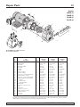
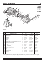
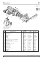
Repair Parts 13
For parts or assistance, call Simer Customer Service at 1-800-468-7867 / 1-800-546-7867
1
2
3
4
5
6
7
7A
8
10
9
11
12
12A
12B
12C
13
14
14
14
17
19
20
16
16
15
15A
9
18
4024 0801
4037 0801
Models
2805E-01
2806E-01
2810E-01
2815E-01
2805E-01
Key Part 2806E-01 2810E-01 2815E-01
No. Description Qty. 1/2 HP 3/4 HP 1 HP
1 Motor 1 J218-577PKG J218-590PKG J218-596PKG
2 Water Slinger 1 17351-0009 17351-0009 17351-0009
3 Seal Plate 1 L3-28 L3-28 L3-28A
4 Seal Plate Gasket 1 345-038 345-038 345-038
5 Shaft Seal 1 U109-6A U109-6A U109-6A
6 Impeller 1 C105-258P C105-258PA C105-258PB
7 Diffuser 1 595-110 595-110 595-109
7A Screws, Diffuser 3 670-698 670-698 670-698
8 Diffuser O-Ring 1 546-032 546-032 546-032
9 Pipe Plug, 3/4" NPT, Hex Head 3 U78-941ZPV U78-941ZPV U78-941ZPVP
10 Quick Connect – Elbow 1 U111-212T U111-212T U111-212T
11 Pipe Plug, 1" NPT Square Head 2 U78-61GPS U78-61GPS U78-61GPS
12 Shallow Well Injector Assembly 1 992-872 992-873 992-874
12A Nozzle 1 541-010 541-008 541-009
12B Venturi Tube 1 830-057 830-055 830-056
12C Deep Well Cap 1 143-093 143-093 143-093
13 Pump Body 1 404-144 404-144 404-144
14 Capscrews, 3/8-16x1-3/4" 4 U30-75ZP U30-75ZP U30-75ZP
15 Base 1 J104-9 J104-9 J104-9
15A Motor Pad 1 C35-5 C35-5 C35-5
16 Capscrew, 3/8-16x1" 2 U30-74ZP U30-74ZP U30-74ZP
17 Tubing, Pressure Switch 1 U37-673ZP U37-673ZP U37-673ZP
18 Pressure Switch 1 U217-1218 U217-1218 U217-1202
19 Lock Nut 1 U36-112ZP U36-112ZP U36-112ZP
20 Connector 1 L43-5C L43-5C L43-5C
Model MDWC Deep Well Conversion
Kit - Purchase Separately.
Purchase Deep Well Conversion Kit, Model MDWC, separately. Kit includes Deep Well Plug (replaces Shallow
Well Injector), Control Valve (replaces Fill Plug), and Pressure Gauge.

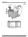
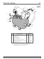
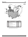
Repair Parts 14
For parts or assistance, call Simer Customer Service at 1-800-468-7867 / 1-800-546-7867
3
5
4024 0801 w/ Tank
1
2
3
4
6
7
8
9
Model
2806E-01
Key Part 2806E-01
No. Description Qty. 1/2 HP
1 Pump 1 †
2 Fitting, PVC 1 322-006
3 Clamp, Hose 2 U19-55SS
4 Hose, Clear 1 403-005
5 Fitting, 90 Deg. 1 322-004
6 Tank, HT7, 15 Gal. Horiz. 1 HT7-02
7 Carriage Bolt, 5/16 -18 X 1-1/4" 2 U30-231ZP
8 Washer, 3/8" Reg. 1-7/16" 2 U43-62ZP
9 Nut, 5/16 -18 2 U36-37ZP
** Pump/Tank Assembly 1 992-871
† For pump parts see the Previous Page.
** Includes Key Numbers 2, 3, 5, 7, 8, and 9,
plus No. 992-872 Shallow Well Injector Assembly.

Sécurité 15
Pour obtenir des pièces ou de l’aide, appeler le Service à la clientèle Simer en composant le 1 800 468-7867/1 800 546-7867
LIRE TOUTES CES INSTRUCTIONS
ET LES SUIVRE!
Ce symbole indique qu'il faut être prudent.
Lorsque ce symbole apparaît sur la pompe ou dans
cette Notice, rechercher une des mises en garde qui
suivent, car elles indiquent un potentiel possible de
blessures corporelles :
avertit d'un danger qui causera des
blessures corporelles, la mort ou des dommages
matériels importants si on l'ignore.
avertit d'un danger qui risque de causer
des blessures corporelles, la mort ou des dommages
matériels importants si on l'ignore.
avertit d'un danger qui causera ou qui
risquera de causer des blessures corporelles, la mort ou
des dommages matériels importants si on l'ignore.
Le mot NOTA indique des instructions spéciales et
importantes n'ayant aucun rapport avec les dangers.
Lire attentivement toutes les consignes de sécurité
contenues dans cette Notice ou collées sur la pompe.
Garder les autocollants de sécurité en bon état; les
remplacer s'ils manquent ou s'ils ont été endommagés.
SÉCURITÉ CONCERNANT
L'ÉLECTRICITÉ
Tension dangereuse. Risque de secouss-
es électriques, de brûlures, voire de mort. La tension du
condensateur peut être dangereuse. Pour décharger le
condensateur du moteur, tenir un tournevis à manche
isolé PAR LE MANCHE et mettre en court-circuit les
bornes du condensateur. Ne pas toucher la lame
métallique du tournevis ni les bornes du condensateur.
En cas de doute, consulter un électricien qualifié.
SÉCURITÉ GÉNÉRALE
Risque de brûlures. Ne pas toucher un
moteur qui fonctionne. Les moteurs modernes sont
conçus pour fonctionner par des températures élevées.
Pour ne pas se brûler lorsque l'on interviendra sur la
pompe, la laisser refroidir pendant 20 minutes après
l'avoir arrêtée avant de la toucher.
Ne pas laisser geler la pompe ni aucun autre élément du
système, sinon la garantie sera annulée.
Ne pomper que de l'eau avec cette pompe.
Périodiquement, inspecter la pompe et tous les éléments
du système.
Toujours porter des lunettes de sécurité lorsque l'on
intervient sur une pompe.
Garder la zone de travail propre, non encombrée et bien
éclairée; tous les outils et tout l'équipement non utilisés
doivent être entreposés correctement.
Ne pas laisser les visiteurs s'approcher de la zone de travail.
Pression dangereuse. Risque d’explosion.
Le corps de la pompe peut exploser si la pompe est util-
isée en tant que pompe de surpression, à moins qu'une
soupape de sûreté pouvant laisser passer le débit maxi-
mum de la pompe à 75 lb/po
2
soit posée.
AVERTISSEMENT
Pression dangereuse!
Poser une soupape de sûreté
sur le tuyau de refoulement.
Dissiper toute la pression
du système avant d'intervenir
sur un élément.
AVERTISSEMENT
Tension dangereuse. Risque
de secousses électriques, de
brûlures, voire de mort.
Mettre à la terre la pompe
avant de la brancher sur le
courant électrique. Couper
l'arrivée de courant avant d'in-
tervenir sur la pompe, sur le
moteur ou sur le réservoir.
Câbler le moteur en
fonction de la bonne
tension. Voir la Section
«Électricité» de cette Notice
et la plaque signalétique du
moteur.
Mettre à la terre le
moteur avant de le
brancher sur le courant
électrique.
Conforme au Code
national de l'électric-
ité, au Code canadien de
l'électricité et aux codes
municipaux pour tous les
câblages.
Respecter les instructions de câblage figurant dans
cette Notice lorsque l'on branche le moteur sur
une ligne haute tension.

Table des matières 16
Merci d'avoir acheté une pompe de qualité supérieure mise à l'essai à l'usine.
Page
Consignes de sécurité générales.........................................................................15
Garantie.............................................................................................................16
Remplacement d’une pompe existante ..............................................................17
Installation sur un nouveau puits peu profond ..........................................18 et 19
• Installation de la pointe filtrante
• Installation sur un puits tubé de 2 pouces
de diamètre ou plus grand
• Installation dans le cas d’eaux de surface
Installation sur un nouveau puits profond .................................................19 et 20
• Puits de 4 pouces de diamètre ou plus grand
• Puits de 2 pouces
• Branchement sur un réservoir préchargé
• Branchement sur un réservoir standard
Électricité..................................................................................................21 et 22
Préparations avant le démarrage de la pompe - Puits profond ...........................23
Préparations avant le démarrage de la pompe - Puits peu profond ...................24
Recherche des pannes .......................................................................................25
Pièces de rechange ..................................................................................26 et 27
ATTACHER LE REÇU D'ORIGINE ICI À DES FINS DE GARANTIE
SIMER garantit à l’acheteur-utilisateur initial de ses produits (“Acheteur”) contre tout défaut de fabrication et de matériaux.
Tout produit reconnu défectueux dans les douze (12) mois qui suivent la date d’achat d’origine sera remplacé ou réparé à la discrétion de
SIMER, selon les conditions stipulées ci-dessous. La preuve d’achat est exigée pour déterminer l’admissibilité à la garantie.
Exceptions à la garantie de douze (12) mois
Produits/N
o
de modèle Période de garantie
M40P, M80,BW85P, CM10, CMK 90 jours
2330, 2300, 2955, 2957, A5500 2 ans
4" Submersible Well Pumps, 3984, 3983, 2975PC, 2958, 3075SS 3 ans
Pre-Charge Water System Tank, 3986, 3985, 2956, 2960 5 ans
3988, 3995, 3997, 3963 À vie
Conditions générales
L’Acheteur s’engage à payer tous les frais de main-d’œuvre et d’expédition nécessaires au remplacement du produit couvert par la garan-
tie. Cette garantie ne couvrira pas les cas de force majeure, et ne s’appliquera pas aux produits qui, du seul avis de SIMER, ont fait l’ob-
jet de négligence, d’utilisation abusive ou incorrecte, d’accident, de modification ou d’altération ; ni aux produits qui n’ont pas été installés,
utilisés, entreposés ou entretenus correctement ; ni à ceux qui n’ont pas été utilisés ou entretenus normalement, y compris, mais sans s’y
limiter, aux produits ayant des pannes de fonctionnement causées par la corrosion, la rouille ou autre corps étranger dans le système, ou
à des produits ayant fonctionné à des pressions dépassant la limite maximale recommandée.
Les demandes de service en vertu de la présente garantie seront faites en retournant le produit défectueux au détaillant ou à SIMER dès la dé-
couverte de tout défaut allégué. SIMER prendra alors les mesures correctives aussi rapidement qu’il est raisonnablement possible. Aucune de-
mande de service en vertu de la présente garantie ne sera acceptée si elle est reçue plus de 30 jours après l’expiration de la dite garantie.
La présente garantie énonce la totalité des obligations de SIMER et le seul recours possible de l’Acheteur dans le cas de produits défectueux.
SIMER NE SERA TENU RESPONSABLE D’AUCUN DOMMAGE INDIRECT, ACCIDENTEL OU FORTUIT QUEL QU’IL SOIT.
LES PRÉSENTES GARANTIES SONT EXCLUSIVES ET TIENNENT LIEU DE TOUTE AUTRE GARANTIE EXPRESSE. LES GARANTIES
IMPLICITES, Y COMPRIS, MAIS SANS S’Y LIMITER, LES GARANTIES IMPLICITES AYANT TRAIT À LA COMMERCIABILITÉ ET À
L’ADAPTATION À UN USAGE PARTICULIER, NE DÉPASSERONT PAS LA DURÉE DES GARANTIES EXPRESSES APPLICABLES STIPU-
LÉES DANS LES PRÉSENTES.
Certaines provinces n’autorisent pas d’exclure ou de limiter les dommages fortuits ou indirects ou de limiter la durée d’une garantie impli-
cite ; il se peut donc que les limitations ou exclusions ci-dessus ne s’appliquent pas à votre cas. La présente garantie vous donne des droits
juridiques spécifiques et vous pouvez en avoir d’autres qui varient d’une province à l’autre.
SIMER • 293 Wright Street • Delavan, WI U.S.A. 53115
Téléphone: 1-800-468-7867/1-800-546-7867 • Télécopieur: 1-800-390-5351

Remplacement d'une pompe existante 17
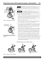
PUITS PEU PROFOND (Figure 1)
Tension dangereuse. Risque de secousses électriques, de brûlures,
voire de mort. Couper le courant alimentant la pompe avant d’intervenir sur la
pompe ou sur le moteur.
1. Vider toute l’eau de l’ancienne pompe; déposer l’ancienne pompe. Vérifier la
tuyauterie à la recherche de dépôts de tartre, de chaux, de rouille, etc.; remplac-
er la tuyauterie au besoin.
2. Brancher la pompe sur le système (Se reporter aux Figures 4, 5 et 6). S’assurer
que tous les raccords du tuyau d’aspiration sont bien étanches, aussi bien à l’air
qu’à l’eau. Si le tuyau d’aspiration aspire de l’air, la pompe ne pompera pas
l’eau du puits.
3. Régler la hauteur de montage de la pompe de façon que les raccords de
plomberie n’exercent aucune contrainte sur le corps de la pompe. Supporter les
tuyaux de façon que le corps de la pompe ne supporte pas le poids de la tuyau-
terie, ni celui des raccords.
PUITS PROFOND
Tension dangereuse. Risque de secousses électriques, de brûlures,
voire de mort. Couper le courant alimentant la pompe avant d’intervenir sur la
pompe ou sur le moteur.
1. Vider toute l’eau de l’ancienne pompe; déposer l’ancienne pompe. Vérifier la
tuyauterie à la recherche de dépôts de tartre, de chaux, de rouille, etc.; remplac-
er la tuyauterie au besoin.
2. Poser une vanne de régulation, un manomètre et un obturateur pour puits pro-
fond dans le corps de la pompe (cette trousse doit être achetée séparément; se
reporter à la Figure 2). Lorsque l’on procède au branchement sur la tête du
puits, s’assurer de brancher un petit orifice sur un petit orifice (eau motrice) et
un grand orifice sur un grand orifice (aspiration). Au besoin, utiliser des tuyaux
flexibles et les tordre pour pouvoir procéder aux bons branchements.
3. Le tuyau d’aspiration (le plus grand orifice) des pompes Simer se trouve sous
l’orifice de l’eau motrice (Se reporter aux Figures 2 et 3).
4. Brancher la pompe sur le système. S’assurer que tous les raccords du tuyau
d’aspiration sont bien étanches, aussi bien à l’air qu’à l’eau. Si le tuyau d’aspira-
tion aspire de l’air, la pompe ne pompera pas l’eau du puits.
5. Régler la hauteur de montage de la pompe de façon que les raccords de
plomberie n’exercent aucune contrainte sur le corps de la pompe. Supporter les
tuyaux de façon que le corps de la pompe ne supporte pas le poids de la tuyau-
terie, ni celui des raccords.
NOTA : L’ancien éjecteur (celui qui est dans le puits) ne s’assortira peut-être pas
bien à la pompe neuve. Si le débit de la pompe neuve n’est pas adéquat, nous
recommandons de poser un nécessaire d’éjecteur Simer MDWE (pour puits de 4
pouces) ou un système d’éjecteur Simer MDWA (pour puits tubé de 2 pouces).
Pour obtenir des pièces ou de l’aide, appeler le Service à la clientèle Simer en composant le 1 800 468-7867/1 800 546-7867
Control Valve
Port plugged
Pressure Gauge
Port plugged
Drive Pipe
Port plugged
Shallow Well
Injector Installed
4026 0801
To Household
From Well
The Drive Pipe
sends the water
down the well
and
drives
the
water up through
the Suction Pipe
to the Pump
Suction Port.
1799 0497 SIM
Discharge Port
Drive Port
Suction Port
4032 0801
Install Control
Valve
Install
Pressure
Gauge
Drive Pipe
To Well
Installed
Remove Shallow Well
Injector and Install
Deep Well Plug
To Household
From Well
Figure 1 : Branchement sur un puits
peu profond
Figure 3 : Fonctions d’aspiration et
de l’eau motrice sur un puits peu
profond
Figure 2 : Branchement sur un puits
peu profond
Orifice de la vanne de
régulation bouché
Vers l’habitation
Orifice du
manomètre bouché
Injecteur pour
puits peu pro-
fond installé
Orifice du tuyau d’eau
motrice bouché
Vers l’habitation
Tuyau d’eau
motrice vers
le puits
installé
En provenance
du puits
Orifice de refoulement
Orifice d’eau motrice
Le tuyau d’eau
motrice envoie l’eau
dans le fond du puits,
puis
renvoie
l’eau par
le tuyau d’aspiration,
vers l’orifice de la
pompe.
Orifice
d’aspiration
Poser la vanne de
régulation
Déposer l’in-
jecteur pour
puits peu pro-
fond, puis poser
l’obturateur pour
puits profond
Poser le
manomètre
En provenance du puits

Installation sur un nouveau puits peu profond 18
INSTALLATIONS DE LA POMPE À ÉJECTEUR SUR
UN PUITS PEU PROFOND
• La profondeur verticale entre la pompe et l’eau pompée ne doit pas dépasser 25
pieds.
• Un seul tuyau entre le puits et le corps de la pompe.
• Peut être installé sur un puits foré ou sur une pointe filtrante.
INSTALLATION DE LA POINTE FILTRANTE (Figure 4)
1. Enfoncer la pointe dans le sol, en utilisant des «raccords d’enfoncement» et des
«chapeaux de battage». Les «raccords d’enfoncement» sont filetés sur toute leur
longueur, ce qui permet aux extrémités des tuyaux de venir en butée l’une con-
tre l’autre de façon que la force d’enfoncement du maillet soit absorbée par le
tuyau et non pas par les filets. Les raccords ordinaires que l’on trouve dans les
quincailleries ne sont pas filetés sur toute leur longueur et ils risquent de s’écras-
er sous l’impact des coups. Les «raccords d’enfoncement» sont également plus
lisses que les raccords de plomberie standard, ce qui leur permet de pénétrer
plus facilement dans le sol.
2. Installer la pompe aussi près que possible du puits.
3. Utiliser le moins possible de raccords (en particulier des coudes) pour brancher la
tuyauterie de la pointe filtrante sur l’orifice d’aspiration de la pompe. Le diamètre
du tuyau d’aspiration doit être au moins aussi grand que le diamètre de l’orifice
d’aspiration de la pompe (y compris le clapet de non retour – Se reporter à la
Figure 5). Supporter le tuyau de façon qu’il ne fléchisse pas et qu’il n’exerce pas
de contraintes sur le corps de la pompe; de plus, il doit être légèrement incliné
vers le haut, du puits jusqu’à la pompe (les points hauts risquent de causer des
poches d’air, lesquelles peuvent causer des bouchons d’air dans la pompe).
Rendre étanches les raccords du tuyau d’aspiration avec du ruban d‘étanchéité en
téflon ou une pâte pour raccords filetés à base de téflon. Les raccords doivent être
étanches à l’air et à l’eau. Si le tuyau d’aspiration aspire de l’air, la pompe ne
pompera pas l’eau du puits. Si une pointe filtrante ne fournit pas suffisamment
d’eau, considérer brancher deux ou trois pointes filtrantes sur un même tuyau
d’aspiration.
INSTALLATION SUR UN PUITS TUBÉ DE 2 POUCES
DE DIAMÈTRE OU PLUS GRAND (Figure 5)
1. Installer la pompe aussi près que possible du puits.
2. Brancher le clapet de pied, la crépine et le tuyau du puits (Se reporter à la
Figure 6). S’assurer que le clapet de pied fonctionne librement.
3. Abaisser le tuyau dans le puits jusqu’à ce que la crépine soit à cinq pieds du
fond du puits. Pour que la pompe n’aspire pas d’air, la crépine doit être au
moins à 10 pieds sous le niveau de l’eau du puits pendant que la pompe fonc-
tionne. Poser un joint sanitaire sur le puits.
4. Poser un té d’amorçage et un bouchon d’amorçage sur la pompe, puis brancher
le tuyau d’aspiration sur la pompe. Brancher le tuyau provenant du puits sur
l’orifice d’aspiration de la pompe en utilisant le moins possible de raccords - en
particulier des coudes - étant donné que les raccords augmentent le frottement
de l’eau dans les tuyaux. Le diamètre du tuyau d’aspiration doit être au moins
aussi grand que le diamètre de l’orifice d’aspiration de la pompe. Utiliser du
ruban d’étanchéité en téflon ou de la pâte pour raccords filetés à base du téflon
sur les raccords filetés. Si le tuyau d’aspiration aspire de l’air, la pompe ne pom-
pera pas l’eau du puits. Supporter le tuyau de façon qu’il ne fléchisse pas et
qu’il n’exerce pas de contraintes sur le corps de la pompe; de plus, il doit être
légèrement incliné vers le haut, du puits jusqu’à la pompe (les points hauts
risquent de causer des poches d’air, lesquelles peuvent causer des bouchons
d’air dans la pompe).
Pour obtenir des pièces ou de l’aide, appeler le Service à la clientèle Simer en composant le 1 800 468-7867/1 800 546-7867
To Household
Water System
Not
to
Scale
Check
Valve
Relief
Valve
2097 0497 SIM
Drive
Coupling
Drive
Point
Drive point below
water level
Priming
Tee and
Plug
To Ho usehold
Water System
Not
to
Scal
e
Check
Valve
Relief
Valve
4033 0801
Suction Pipe
From Well
Priming
Tee and
Plug
Well
Casing
Foot
Valve
Sanitary
Well Seal
Strainer
5-10'
At least
10'
Figure 5 : Installation type sur un
puits tubé
Figure 4 : Installation type sur une
pointe filtrante
Soupape
de sûreté
Vers le système
d’alimentation en
eau de l’habitation
Clapet de
non retour
Pointe filtrante plus
basse que le niveau
de l’eau
Pas à
l’échelle
Pointe
filtrante
Raccord d’enfon-
cement de la
pointe filtrante
Soupape
de sûreté
Clapet de
non retour
Vers le système
d’alimentation en
eau de l’habitation
Tuyau d’aspira-
tion provenant
du puits
Té et bouchon
d’amorçage
Joint sanitaire
du puits
De 5 à 10 pi
Au moins
10 pi
Crépine
Clapet
de pied
Tubage
du puits
Té et
bouchon
d’amorçage
Pas à
l’échelle

Installation sur un nouveau puits peu profond 19
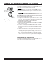
INSTALLATION DANS LE CAS D’EAUX DE SURFACE
(Figure 5)
1. Installer la pompe aussi près que possible du puits en utilisant le moins possible
de raccords (en particulier des coudes) sur le tuyau d’aspiration. Le diamètre du
tuyau d’aspiration doit être au moins aussi grand que le diamètre de l’orifice
d’aspiration de la pompe.
2. Assembler le clapet de pied et le tuyau d’aspiration. S’assurer que le clapet de
pied fonctionne librement. Utiliser du ruban d’étanchéité en téflon. Poser une
crépine autour du clapet de pied pour le protéger contre les poissons, les
déchets, etc.
3. Abaisser le tuyau dans le puits jusqu’à ce que la crépine soit à cinq pieds du fond
du puits. Pour que la pompe n’aspire pas d’air, la crépine doit être au moins à 10
pieds sous le niveau de l’eau du puits pendant que la pompe fonctionne.
4. Poser un té d’amorçage et un bouchon d’amorçage sur la pompe, puis brancher
le tuyau d’aspiration sur la pompe. Supporter le tuyau de façon qu’il ne fléchisse
pas et qu’il n’exerce pas de contraintes sur le corps de la pompe; de plus, il doit
être légèrement incliné vers le haut, du puits jusqu’à la pompe (les points hauts
risquent de causer des poches d’air, lesquelles peuvent causer des bouchons
d’air dans la pompe). Rendre étanches les raccords du tuyau d’aspiration avec
du ruban d‘étanchéité en téflon ou une pâte pour raccords filetés à base de
téflon. Les raccords doivent être étanches à l’air et à l’eau. Si le tuyau d’aspira-
tion aspire de l’air, la pompe ne pompera pas l’eau du puits.
PUITS D’UN DIAMÈTRE DE 4 POUCES OU PLUS
GRAND (Figure 7)
1. Poser une vanne de régulation, un manomètre et un obturateur pour puits pro-
fond dans le corps de la pompe. Se reporter à la Figure 2. Acheter le nécessaire
de conversion pour puits profond, modèle MDWC, pour obtenir ces pièces.
2. Installer la pompe aussi près que possible du puits.
3. Brancher un tuyau flexible entre la tête du puits et la pompe de façon à obtenir
un bon branchement. Brancher le petit orifice sur le petit orifice et le grand ori-
fice sur le grand orifice.
NOTA : L’orifice d’aspiration (le plus grand orifice) des pompes à éjecteur Simer
se trouve sous l’orifice de l’eau motrice. Se reporter à la Figure 3.
4. Brancher le tuyau d’aspiration et le tuyau d’eau motrice sur la tuyauterie de l’é-
jecteur, puis abaisser l’éjecteur dans le puits jusqu’à ce qu’il soit à cinq pieds du
fond du puits. Pour que la pompe n’aspire pas d’air, l’éjecteur doit également être
à au moins 10 pieds sous le niveau de l’eau pendant que la pompe fonctionne.
5. Poser un joint sanitaire sur le puits, puis brancher la tuyauterie de l’éjecteur sur
la pompe. Dans le cas de tuyaux en plastique souples, utiliser des mamelons en
acier là où les tuyaux traversent le joint d’étanchéité du puits pour éviter
d’écraser les tuyaux en plastique lors du serrage du joint.
6. Supporter le tuyau de façon qu’il ne fléchisse pas et qu’il n’exerce pas de con-
traintes sur le corps de la pompe; de plus, il doit être légèrement incliné vers le
haut, du puits jusqu’à la pompe (les points hauts risquent de causer des poches
d’air, lesquelles peuvent causer des bouchons d’air dans la pompe). Rendre
étanches les raccords du tuyau d’aspiration avec du ruban d‘étanchéité en
téflon. Les raccords doivent être étanches à l’air et à l’eau. Si le tuyau d’aspira-
tion aspire de l’air, la pompe ne pompera pas l’eau du puits.
Pour obtenir des pièces ou de l’aide, appeler le Service à la clientèle Simer en composant le 1 800 468-7867/1 800 546-7867
Installation sur un nouveau puits profond
To Household
Water System
Not
to
Scale
Check
Valve
Relief
Valve
4034 0801
Suction Pipe
From Well
Priming
Tee and
Plug
Foot
Valve
Screen
10'
Min.
5–10'
To Household
Water System
Not
to
Scale
Relief
Valve
4035 0801
Suction Pipe
From Well
If well head and pump
ports don't match, twist
reinforced flexible pipe
to make connections.
Well
Head
Venturi
Nozzle
Ejector
Foot Valve
Strainer
Drive Pipe
To Well
Figure 7 : Installation type sur un
puits profond de 2 ou de 4 pouces
Figure 6 : Installation type sur une
nappe d’eau libre
Soupape
de sûreté
Té et bouchon
d’amorçage
Tuyau d’aspira-
tion provenant
du puits
Clapet de
non retour
Vers le système
d’alimentation en
eau de l’habitation
Pas à
l’échell
e
Au moins
10 pi
Clapet
de pied
De 5 à 10 pi
Crépine
Vers le système
d’alimentation en
eau de l’habitation
Tuyau d’eau motrice
vers le puits
Tuyau d’aspiration
provenant du puits
Si le diamètre de la tête du
puits et des orifices de la
pompe ne correspondent
pas, déformer le tuyau sou-
ple renforcé pour pouvoir
procéder aux branchements.
Venturi
Éjecteur
Buse
Clapet de pied
Crépine
Tête du
puits
Soupape
de sûreté
Pas à
l’échelle

Installation sur un nouveau puits profond 20
PUITS DE 2 POUCES (Figure 8)
1. Poser une vanne de régulation, un manomètre et un obturateur pour puits pro-
fond dans le corps de la pompe. Se reporter à la Figure 2. Acheter le nécessaire
de conversion pour puits profond, modèle MDWC, pour obtenir ces pièces.
2. Installer la pompe aussi près que possible du puits.
3. Brancher un tuyau flexible entre la tête du puits et la pompe de façon à obtenir
un bon branchement. Brancher le petit orifice sur le petit orifice et le grand ori-
fice sur le grand orifice.
NOTA : L’orifice d’aspiration (le plus grand orifice) des pompes à éjecteur Simer
se trouve sous l’orifice de l’eau motrice. Se reporter à la Figure 3.
4. Brancher le tuyau d’eau motrice et le tuyau d’aspiration entre le puits et la
pompe. Supporter le tuyau de façon qu’il ne fléchisse pas et qu’il n’exerce pas
de contraintes sur le corps de la pompe; de plus, il doit être légèrement incliné
vers le haut, du puits jusqu’à la pompe (les points hauts risquent de causer des
poches d’air, lesquelles peuvent causer des bouchons d’air dans la pompe).
Rendre étanches les raccords du tuyau d’aspiration avec du ruban d‘étanchéité
en téflon ou une pâte pour raccords filetés à base de téflon. Les raccords
doivent être étanches à l’air et à l’eau. Si le tuyau d’aspiration aspire de l’air, la
pompe ne pompera pas l’eau du puits.
BRANCHEMENT SUR UN RÉSERVOIR PRÉCHARGÉ
(Figure 9)
Si un réservoir préchargé est utilisé sur le système d’eau, il devra être branché sur la
pompe comme il est illustré à la Figure 9. La soupape de sûreté doit pouvoir laisser
passer le débit maximum de la pompe à une pression de 100 lb/po
2
.
Vérifier la précharge de l’air dans le réservoir à l’aide d’un manomètre pour pneus.
La précharge se mesure
lorsqu’il n’y a pas de pression d’eau dans le réservoir.
Couper le courant alimentant la pompe, puis vider le réservoir avant de vérifier sa
précharge. La pompe est équipée d’un pressostat qui fonctionne automatiquement
entre 20 et 40 lb/po
2
(modèles 2805/6/10E) ou entre 30 et 50 lb/po
2
(modèle 2815E)
de façon à toujours avoir une pression de précharge de 18 lb/po
2
(modèles
2805/6/10E) ou de 28 lb/po
2
(modèle 2815E) dans le réservoir. Autrement dit, la
précharge doit être de 2 lb/po
2
inférieure au réglage de la pression de démarrage de
la pompe par le pressostat.
AUCUN régulateur de débit d’air n’est requis sur les réservoirs préchargés; l’orifice
de 1/4 de pouce NPT prévu à cet effet sur le corps de la pompe devra donc être
bouché.
BRANCHEMENT SUR UN RÉSERVOIR STANDARD
(Figure 10)
Si un réservoir standard est utilisé sur le système d’eau, il devra être branché sur la
pompe comme il est illustré à la Figure 10. La soupape de sûreté utilisée avec un
réservoir standard doit pouvoir laisser passer le débit maximum de la pompe à une
pression de 75 lb/po
2
.
Brancher le tube du régulateur de débit d’air sur l’orifice de 1/4 de pouce prévu à
cet effet sur le corps de la pompe. Brancher le tube entre l’orifice du régulateur de
débit d’air de la pompe et l’orifice du régulateur de débit d’air monté sur le réser-
voir. Pour plus de détails, se reporter aux instructions fournies avec le réservoir et le
régulateur de débit d’air.
Étanchéité des raccords des tuyaux
Utiliser du ruban d’étanchéité en téflon ou de la pâte d’étanchéité pour rac-
cords filetés à base de téflon pour rendre étanches les raccords branchés sur la
pompe. Ne pas utiliser de pâte pour raccords filetés sur les pompes en plas-
tique, car ces produits risquent de réagir avec le plastique des composants à la
pompe. S’assurer que tous les raccords du tuyau d’aspiration sont bien étanch-
es, aussi bien à l’air qu’à l’eau.
Si le tuyau d’aspiration aspire de l’air, la pompe
ne pompera pas l’eau du puits.
Pour obtenir des pièces ou de l’aide, appeler le Service à la clientèle Simer en composant le 1 800 468-7867/1 800 546-7867
To the Household
Water System
Relief Valve
To
Waste
Pressure
Switch
2110 0497 SIM
Suction Pipe
From
the Well
Plugged
AVC
Port
Drive Pipe
To
the Well
To Household
Water System
Pressure
Switch
Suction Pipe
From Well
Air Volume
Control
Air Volume
Control Tube
Relief
Valve
Drive Pipe To Well
Figure 9 : Branchements sur un réser-
voir préchargé
To Household
Water System
Not
to
Scale
Relief Valve
4035 0801
Suction Pipe
From Well
If well head and pump
ports don't match, twist
reinforced flexible pipe
to make connections.
Drive Pipe
To Well
Well Head
41
JET NO.
J32P-
24
Well Casing
serves as
Drive Pipe
Suction Pipe
Venturi
Nozzle
Ejector
Leather
Cup Seals
4036 0801
Figure 8 : Installation type sur un
puits profond de 2 pouces
Figure 10 : Branchements sur un réser-
voir standard
Tuyau d’eau
motrice vers
le puits
Soupape de sûreté
Vers le système
d’alimentation
en eau de
l’habitation
Tête du puits
Tuyau d’aspiration
provenant du puits
Venturi
Buse
Éjecteur
Le tubage du
puits sert de
tuyau d’eau
motrice
Si le diamètre de la tête
du puits et des orifices
de la pompe ne corre-
spondent pas, déformer
le tuyau souple renforcé
pour pouvoir procéder
aux branchements.
Tuyau d’eau
motrice vers
le puits
Tuyau d’aspiration
provenant du puits
Vers les
rejets à
l’égout
Vers le système d’alimentation en eau de l’habitation
Soupape de sûreté
Vers le système
d’alimentation en
eau de l’habitation
Régulateur
de débit d’air
Tube du
régulateur de
débit d’air
Tuyau d’eau motrice
vers le puits
Tuyau d’aspiration
provenant du puits
Soupape
de sûreté
Tuyau d’aspiration
Coupelles
d’étanchéité en cuir
Pas à
l’échelle
Pressostat
Orifice du
régulateur
de débit d’air
bouché
Pressostat
La page est en cours de chargement...
La page est en cours de chargement...
La page est en cours de chargement...
La page est en cours de chargement...
La page est en cours de chargement...
La page est en cours de chargement...
La page est en cours de chargement...
La page est en cours de chargement...
La page est en cours de chargement...
La page est en cours de chargement...
La page est en cours de chargement...
La page est en cours de chargement...
La page est en cours de chargement...
La page est en cours de chargement...
La page est en cours de chargement...
La page est en cours de chargement...
La page est en cours de chargement...
La page est en cours de chargement...
La page est en cours de chargement...
La page est en cours de chargement...
-
 1
1
-
 2
2
-
 3
3
-
 4
4
-
 5
5
-
 6
6
-
 7
7
-
 8
8
-
 9
9
-
 10
10
-
 11
11
-
 12
12
-
 13
13
-
 14
14
-
 15
15
-
 16
16
-
 17
17
-
 18
18
-
 19
19
-
 20
20
-
 21
21
-
 22
22
-
 23
23
-
 24
24
-
 25
25
-
 26
26
-
 27
27
-
 28
28
-
 29
29
-
 30
30
-
 31
31
-
 32
32
-
 33
33
-
 34
34
-
 35
35
-
 36
36
-
 37
37
-
 38
38
-
 39
39
-
 40
40


Simer 2806E-01 Le manuel du propriétaire
- Catégorie
- Pompes à eau
- Taper
- Le manuel du propriétaire
- Ce manuel convient également à
dans d''autres langues
Documents connexes
-
Simer 2800, 2800E, 2802, 2802E, 2803 Shallow Well Jet Pump Le manuel du propriétaire
-
-
Simer 3310P Manuel utilisateur
-
Simer 2803 Manuel utilisateur
-
Simer 3110P Le manuel du propriétaire
-
-
-
-
-
Autres documents
-
Simer Pumps 28.1 Manuel utilisateur
-
-
Berkeley SLJ Series Convertible Deep Well Jet Pumps Le manuel du propriétaire
-
Little GIANT JPC-075-C Manuel utilisateur
-
-
-
Pentair 10HL Le manuel du propriétaire
-
 Dorcy 41-1440 Mode d'emploi
-
MYERS HJ, HR Series Jet Pumps Le manuel du propriétaire
-
 BUR-CAM 8748147 Le manuel du propriétaire

