Schumacher John Deere TY27732 Automatic Benchtop Starter/Charger Le manuel du propriétaire
- Catégorie
- Chargeurs de batterie de voiture
- Taper
- Le manuel du propriétaire

TY27732 Automatic Benchtop Starter/
Charger
OPERATOR'S MANUAL
TY27732 Automatic Benchtop
Starter/Charger
OMTY27732 ISSUE E0 (MULTI-LINGUAL)
*OMTY27732*
CALIFORNIA
Proposition 65 Warning
Diesel engine exhaust and some of its constituents
are known to the State of California to cause cancer,
birth defects, and other reproductive harm.
If this product contains a gasoline engine:
WARNING
The engine exhaust from this product contains
chemicals known to the State of California to cause
cancer, birth defects or other reproductive harm.
The State of California requires the above two warnings.
Additional Proposition 65 Warnings can be found in this manual.
Enterprise Parts Portfolio
PRINTED in USA
0099002068-01


TY27732 Automatic Benchtop Starter/
Charger
OPERATOR'S MANUAL
TY27732 Automatic Benchtop
Starter/Charger
OMTY27732 ISSUE E0 (ENGLISH)
*OMTY27732*
CALIFORNIA
Proposition 65 Warning
Diesel engine exhaust and some of its constituents
are known to the State of California to cause cancer,
birth defects, and other reproductive harm.
If this product contains a gasoline engine:
WARNING
The engine exhaust from this product contains
chemicals known to the State of California to cause
cancer, birth defects or other reproductive harm.
The State of California requires the above two warnings.
Additional Proposition 65 Warnings can be found in this manual.
Enterprise Parts Portfolio
PRINTED in USA

Foreword
TYT8157—UN—01APR20
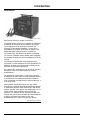
Thank you for purchasing a John Deere product.
Read this manual carefully to learn how to operate and
service your battery charger. Failure to do so results in
personal injury or equipment damage. This manual and
safety signs on your battery charger are available in
other languages. See a John Deere dealer to order.
This manual is considered a permanent part of your
battery charger and must remain with the charger when
you sell it.
Measurements in this manual are given in both metric
and customary U.S. unit equivalents. Use only the
correct replacement parts and fasteners.
To help trace the automatic battery charger if it is stolen,
accurately record all identication numbers.
Warranty is provided as part of the John Deere support
program for customers who operate and maintain their
equipment as described in this manual. Warranty is
explained in the Warranty section at the end of this
manual.
This warranty provides the assurance that John Deere
backs its products when defects appear within the
warranty period. In some circumstances, John Deere
also provides eld improvements, often without a
charge to the customer, even if the product is out of
warranty. If equipment is abused or modied to change
its performance beyond the original factory
specications, warranty is void and eld improvements
can be denied.
GW44282,0000CA9-19-01APR20
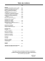
Introduction

Page
Safety
Recognize Safety Information ....................... 05-1
Understand Signal Words ............................ 05-1
Follow Safety Instructions ............................ 05-1
Prevent Battery Explosions .......................... 05-1
Prevent Acid Burns ................................... 05-2
Wear Protective Clothing ............................. 05-2
Decommissioning — Proper Recycling and
Disposal of Fluids and Components ............. 05-2
Handling Batteries Safely ............................ 05-3
Important Safety Instructions-Save These
Instructions .......................................... 05-4
Personal Safety Precautions ......................... 05-4
Prepare for Emergencies ............................. 05-5
Preparing To Charge
Prepare to Charge .................................... 10-1
Charger Location ...................................... 10-1
Battery Location ....................................... 10-1
Grounding and AC Power Cord Connections ..... 10-2
Control Panel
Control Panel .......................................... 15-1
Battery Charging Times .............................. 15-3
Operation
Assembly ............................................... 20-1
Operating Instructions ................................ 20-1
Display Messages
Display Messages ..................................... 25-1
Battery Maintenance
Maintenance and Care ............................... 30-1
Storage
Storage ................................................. 35-1
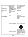
Troubleshooting
Troubleshooting ....................................... 40-1
Specications .......................................... 40-2
Warranty
Warranty ................................................ 45-1
Original Instructions. All information, illustrations and specications in this
manual are based on the latest information available at the time of publication.
The right is reserved to make changes at any time without notice.
COPYRIGHT © 2020
DEERE & COMPANY
Moline, Illinois
All rights reserved.
Contents
i

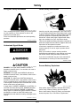
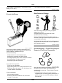
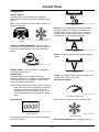
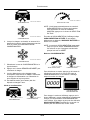
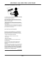
Recognize Safety Information
T81389—UN—28JUN13
This is a safety-alert symbol. When you see this symbol
on your machine or in this manual, be alert to the
potential for personal injury.
Follow recommended precautions and safe operating
practices.
DX,ALERT-19-29SEP98
Understand Signal Words
TS187—19—30SEP88
DANGER; The signal word DANGER indicates a
hazardous situation which, if not avoided, will result in
death or serious injury.
WARNING; The signal word WARNING indicates a
hazardous situation which, if not avoided, could result in
death or serious injury.
CAUTION; The signal word CAUTION indicates a
hazardous situation which, if not avoided, could result in
minor or moderate injury. CAUTION may also be used
to alert against unsafe practices associated with events
which could lead to personal injury.
A signal word—DANGER, WARNING, or CAUTION—is
used with the safety-alert symbol. DANGER identies
the most serious hazards. DANGER or WARNING
safety signs are located near specic hazards. General
precautions are listed on CAUTION safety signs.
CAUTION also calls attention to safety messages in this
manual.
DX,SIGNAL-19-05OCT16
Follow Safety Instructions
TS201—UN—15APR13
Carefully read all safety messages in this manual and
on your machine safety signs. Keep safety signs in good
condition. Replace missing or damaged safety signs. Be
sure new equipment components and repair parts
include the current safety signs. Replacement safety
signs are available from your John Deere dealer.
There can be additional safety information contained on
parts and components sourced from suppliers that is not
reproduced in this operator's manual.
Learn how to operate the machine and how to use
controls properly. Do not let anyone operate without
instruction.
Keep your machine in proper working condition.
Unauthorized modications to the machine may impair
the function and/or safety and aect machine life.
If you do not understand any part of this manual and
need assistance, contact your John Deere dealer.
DX,READ-19-16JUN09
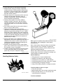
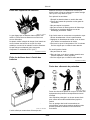
Prevent Battery Explosions
TS204—UN—15APR13
Keep sparks, lighted matches, and open ame away
from the top of battery. Battery gas can explode.
Never check battery charge by placing a metal object
across the posts. Use a volt-meter or hydrometer.
Safety
05-1

Do not charge a frozen battery; it may explode. Warm
battery to 16°C (60°F).
DX,SPARKS-19-03MAR93
Prevent Acid Burns
TS203—UN—23AUG88
Sulfuric acid in battery electrolyte is poisonous. It is
strong enough to burn skin, eat holes in clothing, and
cause blindness if splashed into eyes.
Avoid the hazard by:
1.Filling batteries in a well-ventilated area.
2.Wearing eye protection and rubber gloves.
3.Avoiding breathing fumes when electrolyte is added.
4.Avoiding spilling or dripping electrolyte.
5.Use proper jump start procedure.
If you spill acid on yourself:
1.Flush your skin with water.
2.Apply baking soda or lime to help neutralize the acid.
3.Flush your eyes with water for 15—30 minutes. Get
medical attention immediately.
If acid is swallowed:
1.Do not induce vomiting.
2.Drink large amounts of water or milk, but do not
exceed 2 L (2 quarts).
3.Get medical attention immediately.
DX,POISON-19-21APR93
Wear Protective Clothing
TS206—UN—15APR13
Wear close tting clothing and safety equipment
appropriate to the job.
Prolonged exposure to loud noise can cause
impairment or loss of hearing.
Wear a suitable hearing protective device such as
earmus or earplugs to protect against objectionable or
uncomfortable loud noises.
Operating equipment safely requires the full attention of
the operator. Do not wear radio or music headphones
while operating machine.
DX,WEAR-19-10SEP90
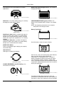
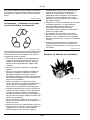
Decommissioning — Proper Recycling and
Disposal of Fluids and Components
TS1133—UN—15APR13
Safety and environmental stewardship measures must
be taken into account when decommissioning a
machine and/or component. These measures include
the following:
● Use appropriate tools and personal protective
equipment such as clothing, gloves, face shields or
glasses, during the removal or handling of objects
and materials.
Safety
05-2

● Follow instructions for specialized components.
● Release stored energy by lowering suspended
machine elements, relaxing springs, disconnecting
the battery or other electrical power, and releasing
pressure in hydraulic components, accumulators,
and other similar systems.
● Minimize exposure to components which may have
residue from agricultural chemicals, such as
fertilizers and pesticides. Handle and dispose of
these components appropriately.
● Carefully drain engines, fuel tanks, radiators,
hydraulic cylinders, reservoirs, and lines before
recycling components. Use leak-proof containers
when draining uids. Do not use food or beverage
containers.
● Do not pour waste uids onto the ground, down a
drain, or into any water source.
● Observe all national, state, and local laws,
regulations, or ordinances governing the handling or
disposal of waste uids (example: oil, fuel, coolant,
brake uid); lters; batteries; and, other substances
or parts. Burning of ammable uids or components
in other than specially designed incinerators may be
prohibited by law and could result in exposure to
harmful fumes or ashes.
● Service and dispose of air conditioning systems
appropriately. Government regulations may require a
certied service center to recover and recycle air
conditioning refrigerants which could damage the
atmosphere if allowed to escape.
● Evaluate recycling options for tires, metal, plastic,
glass, rubber, and electronic components which may
be recyclable, in part or completely.
● Contact your local environmental or recycling center,
or your John Deere dealer for information on the
proper way to recycle or dispose of waste.
DX,DRAIN-19-01JUN15
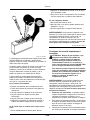
Handling Batteries Safely
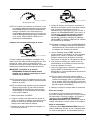
TS204—UN—15APR13
TS203—UN—23AUG88
Battery gas can explode. Keep sparks and ames away
from batteries. Use a ashlight to check battery
electrolyte level.
Never check battery charge by placing a metal object
across the posts. Use a voltmeter or hydrometer.
Always remove grounded (-) battery clamp rst and
replace grounded clamp last.
Sulfuric acid in battery electrolyte is poisonous and
strong enough to burn skin, eat holes in clothing, and
cause blindness if splashed into eyes.
Avoid hazards by:
● Filling batteries in a well-ventilated area
● Wearing eye protection and rubber gloves
● Avoiding use of air pressure to clean batteries
● Avoiding breathing fumes when electrolyte is added
● Avoiding spilling or dripping electrolyte
● Using correct battery booster or charger procedure.
If acid is spilled on skin or in eyes:
1.Flush skin with water.
2.Apply baking soda or lime to help neutralize the acid.
3.Flush eyes with water for 15—30 minutes. Get
medical attention immediately.
If acid is swallowed:
Safety
05-3

1.Do not induce vomiting.
2.Drink large amounts of water or milk, but do not
exceed 2 L (2 qt.).
3.Get medical attention immediately.
WARNING: Battery posts, terminals, and related
accessories contain lead and lead compounds,
chemicals known to the State of California to cause
cancer and reproductive harm. Wash hands after
handling.
DX,WW,BATTERIES-19-02DEC10
Important Safety Instructions-Save These
Instructions
CAUTION: Risk of explosive gases. Working in
the vicinity of lead-acid batteries is dangerous.
Batteries generate explosive gases during
normal battery operation. Read this manual and
follow the instructions exactly EACH TIME you
use this battery charger.
To reduce the risk of battery explosion, follow
these instructions and the instructions
published by the battery manufacturer. Review
the cautionary information on the battery,
battery charger, and engine compartment.
WARNING: Battery posts, terminals, and related
accessories contain lead and lead compounds,
chemicals known by the State of California to cause
cancer and reproductive harm. Wash hands after
handling.
1. Save these instructions. This manual contains
important safety and operating instructions for your
battery charger. Read and understand this manual
before using the battery charger.
2. To reduce the risk of electric shock, do not operate
the battery charger when unit is exposed to water.
Do not expose the battery charger to rain or snow.
3. Use of an attachment not recommended or sold by
the battery charger manufacturer may result in a
risk of re, electric shock, or injury to persons.
4. To reduce the risk of damage to electric plug and
cord, pull by plug rather than cord when
disconnecting battery charger.
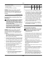
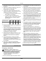
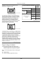
5. Use of an improper extension cord could result in
re or electric shock. When using an extension
cord, make sure:
a. The extension cord is properly wired and in
good electrical condition.
b. The wire size is large enough for the length of
cord for the ampere rating of this battery
charger as specied in table.
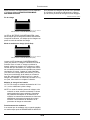
Length of Cord 7.625 m
(25 ft)
15.25 m
(50 ft)
30.5 m
(100 ft)
45.75 m
(150 ft)
Size of Cord 18
gauge
(0.82
mm²)
18
gauge
(0.82
mm²)
18
gauge
(0.82
mm²)
16
gauge
(1.31
mm²)
6. Never alter AC cord or grounding plug provided.
7. Locate battery power cord so it cannot be stepped
on, tripped over, or subjected to damage or stress.
Do not operate the battery charger with damaged
cord or plug. Replace cord or plug immediately.
8. Do not operate the battery charger if it has received
a sharp blow, been dropped, or otherwise damaged
in any way. Take it to a qualied service technician.
9. Do not disassemble the battery charger. Take
charger to a qualied service technician when
service or repair is necessary. Incorrect assembly
may result in electric shock or re.
10. To reduce the risk of electric shock, unplug the
battery charger from the outlet before attempting
any maintenance or cleaning.
OUO6043,0000405-19-25OCT18
Personal Safety Precautions
CAUTION: This product contains one or more
chemicals known to the State of California to
cause cancer and birth defects or other
reproductive harm.
1. Consider having someone close enough by to come
to your aid when you work near a lead-acid battery.
2. Have plenty of fresh water and soap nearby in case
battery acid contacts skin, clothing, or eyes.
3. Wear complete eye protection and clothing
protection. Avoid touching eyes while working near
battery.
4. If battery acid contacts skin or clothing, wash
immediately with soap and water. If acid enters eye,
immediately ood eye with running cold water for at
least 10 minutes and get medical attention
immediately.
5. NEVER smoke or allow a spark or ame in vicinity of
battery or engine.
6. Be extra cautious to reduce the risk of dropping a
metal tool onto battery. It might spark or short-circuit
battery or other electrical part that may cause
explosion.
7. Remove personal metal items such as rings,
bracelets, necklaces, and watches when working
with a lead-acid battery. A lead-acid battery can
produce a short-circuit current high enough to weld a
ring, or the like, to metal, causing a severe burn.
Safety
05-4

8. Use the charger for charging LEAD-ACID (STD,
AGM, or GEL) rechargeable batteries with
recommended rated capacities of 24 Ah (6 V) and
22-59 Ah (12 V). It is not intended to supply power to
a low voltage electrical system other than in a starter-
motor application. Do not use battery charger for
charging dry-cell batteries that are commonly used
with home appliances. These batteries may burst
and cause injury to persons and damage to property.
9. NEVER charge a frozen battery.
MM95366,00003E2-19-22JUN18
Prepare for Emergencies
TS291—UN—15APR13
Be prepared if a re starts.
Keep a rst aid kit and re extinguisher handy.
Keep emergency numbers for doctors, ambulance
service, hospital, and re department near your
telephone.
DX,FIRE2-19-03MAR93
Safety
05-5

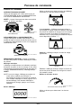
Prepare to Charge
CAUTION: Avoid Contact! Battery acid is a
highly corrosive sulfuric acid!
1. To charge the battery outside of the vehicle, remove
the ground terminal rst. To prevent arcing, turn o all
accessories in the vehicle.
2. Charge the battery in a ventilated area.
3. Clean the battery terminals before charging. Use
baking soda and water to neutralize battery acid and
reduce airborne corrosion. Do not touch eyes, nose,
or mouth.
4. Add distilled water to each cell until battery acid
reaches level specied by the battery manufacturer.
Do not overll. Batteries without the removable cell
caps, such as valve regulated lead acid batteries
(VRLA), follow manufacturer’s recharging
instructions.
5. Study all battery manufacturer-specic precautions
while charging and recommended rates of charge.
6. Refer to the vehicle owner’s manual to determine
battery voltage.
7. Ensure tight charger clip connections.
MM95366,00003A8-19-25OCT18
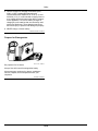
Charger Location
1. Position the charger as far away from the battery as
the DC cables permit.
2. Never place the charger directly over the battery
being charged; gases from the battery can corrode
and damage the charger.
3. Do not set the battery on top of the charger.
4. Never allow battery acid to drip onto charger when
reading electrolyte-specic gravity or lling the
battery.
5. Do not operate the charger in closed-in area or
restrict ventilation.
DC Connection Precautions
1. Connect and disconnect DC output clips only after
setting any charger switches to "o" position (if
applicable) and removing AC cord from the electric
outlet. Never allow the clips to touch each other.
Clips may be energized and they may spark.
2. Attach clips to the battery and chassis, refer to the
Battery Installation section.
MM95366,00003A9-19-11OCT18
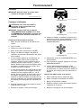
Battery Location
Charging Battery in Vehicle
CAUTION: Prevent battery explosions! Avoid
sparks!
IMPORTANT: If the vehicle hood closes on cables
charger components can be damaged. Ensure
that the hood does not touch the metal part of
the battery clips or cut insulation of cables.
1. Position AC and DC cables to reduce the risk of
damage caused by the hood, door, and moving or hot
engine parts.
2. Stay clear of the fan blades, belts, pulleys, and other
parts that can cause injury.
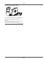
3. Check polarity of the battery posts. POSITIVE (POS,
P, +) battery post usually has a larger diameter than
NEGATIVE (NEG, N, -) post.
4. If the negative post is grounded to chassis (as in
most vehicles), see step 5. If the positive post is
grounded to chassis, see step 6.
5. For a negative-grounded vehicle, connect POSITIVE
(RED) clip from the battery charger to POSITIVE
(POS, P, +) ungrounded post of the battery. Connect
NEGATIVE (BLACK) clip to the vehicle chassis or
engine block away from the battery. Do not connect
the clip to the carburetor, fuel lines, or sheet-metal
body parts. Connect to a heavy gauge metal part of
the frame or engine block.
6. For a positive-grounded vehicle, connect NEGATIVE
(BLACK) clip from the battery charger to NEGATIVE
(NEG, N, -) ungrounded post of battery. Connect
POSITIVE (RED) clip to the vehicle chassis or
engine block away from the battery. Do not connect
the clip to the carburetor, fuel lines, or sheet-metal
body parts. Connect to a heavy gauge metal part of
the frame or engine block.
7. When disconnecting the charger, turn switches to o,
disconnect AC cord, remove clip from the vehicle
chassis, and then remove clip from the battery
terminal.
8. When charging is complete, disconnect the charger
from AC power, remove clip from the vehicle chassis,
and then remove clip from the battery terminal.
Charging Battery Outside Vehicle
CAUTION: Prevent battery explosions! Avoid
sparks!
1. Place the battery in a well-ventilated area.
2. Check polarity of the battery posts. POSITIVE (POS,
P, +) battery post usually has a larger diameter than
NEGATIVE (NEG, N, -) post.
Preparing To Charge
10-1

3. Attach a 61 cm (24 in) 6-gauge (AWG) 13.29 mm²
insulated battery cable (not included with charger) to
NEGATIVE (NEG, N, -) battery post.
4. Connect POSITIVE (RED) charger clip to POSITIVE
(POS, P, +) post of battery.
5. Position yourself and free end of cable previously
attached to the NEGATIVE (NEG, N, -) battery post
as far away from the battery as possible. Connect the
NEGATIVE (BLACK) charger clip to the free end of
the cable.
6. Do not face the battery when making nal
connection.
7. When charging is complete, disconnect the charger
from AC power, remove the clamps from the vehicle
chassis, and then remove the clamp from the battery
terminal.
8. Marine (boat) battery must be removed and charged
on shore. Onboard charging requires equipment
specially designed for marine use.
MM95366,00003AA-19-26OCT18
Grounding and AC Power Cord
Connections
NOTE: According to Canadian Regulations, use of an
adapter plug is not allowed in Canada. Use of an
adapter plug in the United States is not
recommended and not used.
CAUTION: Never alter the AC cord or provided
plug. If it does not t the outlet, have a
grounded outlet installed by a qualied
electrician. Improper connection can result in
the risk of electric shock or electrocution.
1. Use the battery charger on nominal 120 V circuit.
Plug into outlet properly installed and grounded in
accordance with all local codes and ordinances. Plug
pins must t the receptacle (outlet). Do not use with
an ungrounded system.
2. The use of an extension cord is not recommended. If
you must use an extension cord, follow these
guidelines:
● Pins on the plug of extension cord must be the same
number, size, and shape as the plug on the charger.
● Ensure that the extension cord is properly wired and
in good electrical condition.
● Wire size must be large enough for the AC ampere
rating of charger, as specied:
Length of Cord (ft) 7.625 m (25 ft) 15.25 m (50 ft) 30.5 m (100 ft) 45.75 m (150 ft)
AWG* Size of Cord 16 gauge (1.31
mm²)
12 gauge (0.82
mm²)
10 gauge (1.31
mm²)
8 gauge (2.0 mm²)
*AWG-American Wire Gauge
MM95366,00003AB-19-11OCT18
Preparing To Charge
10-2

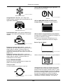
Control Panel
ON-OFF SWITCH
Use this switch to select between the CHARGE/
MAINTAIN rate, BOOST rate, and the ENGINE START
mode.
OFF— when the switch is in this position (middle), the
charger is turned o.
TYT8110—UN—24MAY18
BOOST
TYT8109—UN—24MAY18
CHARGE/MAINTAIN
BOOST or CHARGE/MAINTAIN— when the switch is
in this position, the Rate Selection button can be set to
either the Charge/Maintain 2<>6A or the Boost 40A
setting.
TYT8111—UN—24MAY18
ENGINE START
ENGINE START— when the switch is in this position,
the Engine Start LED is on.
Digital Display
The Digital Display gives a digital indication of
amperage, voltage, or % of charge. If you manually stop
the charging process (by pressing the START/STOP
button), the display shows
OFF
.
NOTE: During charging, the display could go into sleep
mode and will not show the amperage, percentage
of charge or voltage of the battery. To turn the
display back on, press the Display button. To turn
o the display and save energy, press the display
button.
Display Button
TYT8105—UN—24MAY18
DISPLAY BUTTON
Use this button to set the function of the digital display to
one of the following:
TYT8106—UN—24MAY18
BATTERY %
Battery %— the digital display shows an estimated
charge percentage of the battery connected to the
chargers battery clamps, when charging. When the
starting battery voltage is below 8.0 V, the battery
percentage is not yet available and shows “----”.
TYT8107—UN—24MAY18
AMPS
Amps— the display shows the approximate charging
current.
TYT8104—UN—24MAY18
VOLTAGE
Voltage— the Digital Display shows the voltage at the
charger battery clamps in DC volts.
Rate Selection Button
TYT8108—UN—24MAY18
RATE SELECTION BUTTON
Use this button to select one of the following rates:
TYT8109—UN—24MAY18
CHARGE MAINTAIN
2A<>6A Charge/Maintain— for charging small and
Control Panel
15-1

large batteries. Not recommended for industrial
applications.
TYT8110—UN—24MAY18
40A BOOST
40A Boost— for quickly adding energy to a severely
discharged or large capacity battery.
TYT8111—UN—24MAY18
ENGINE START
200A Engine Start (12 V)— provides 200 amps for
starting an engine with a weak or run-down battery.
Always use in combination with a battery. Provides
250A of the engine start capabilities for 12 V battery
systems.
150A Engine Start (6 V)— provides 150 amps for
starting an engine with a weak or run-down battery.
Always use in combination with a battery.
START/STOP Button
Press to immediately begin charging your properly
connected battery.
LED Indicators
LEDs light to indicate the following:
TYT8113—UN—24MAY18
REVERSED CLAMPS
CLAMPS REVERSED (red) LED ashing— the
connections are reversed.
TYT8112—UN—24MAY18
ON
BOOST/ON (yellow/orange) LED lit— the charger is
charging the battery.
TYT8119—UN—24MAY18
CHARGED/MAINTAINING
CHARGED/MAINTAINING (green) LED lit— the
battery is fully charged and the charger is in maintain
mode.
NOTE: See Operating Instructions for a complete
description of the charger modes.
Battery Type Button
TYT8118—UN—24MAY18
BATTERY TYPE BUTTON
Use this button to select the type of battery.
TYT8117—UN—24MAY18
STD
Used in cars, trucks, and motorcycles, these batteries
have vent caps and are often marked "low
maintenance" or "maintenance-free". This type of
battery is designed to deliver quick bursts of energy
(such as starting engines) and has a greater plate
count. The plates are thinner and have dierent material
composition. Standard batteries should not be used for
deep-cycle applications.
TYT8116—UN—24MAY18
ABSORBED GLASS MAT
The Absorbed Glass Mat construction allows the
electrolyte to be suspended near the active material of
the plates. In theory, this enhances both the discharge
Control Panel
15-2

and recharge eciency. The AGM batteries are a
variant of Sealed VRLA (valve regulated lead-acid)
batteries. Popular uses include high-performance
engine starting, power sports, deep-cycle, solar, and
storage batteries.
TYT8115—UN—24MAY18
GEL
The electrolyte in a GEL cell has a silica additive that
causes it to set up or stien. The recharge voltages on
this type of cell are lower than those for other styles of
the lead-acid battery. This is probably the most sensitive
cell in terms of adverse reactions to the over voltage
charging. Gel batteries are best used in VERY deep-
cycle application and may last a bit longer in hot-
weather applications. If the wrong battery charger is
used on a gel cell battery, poor performance and
premature failure results.
MM95366,00003D1-19-25OCT18
Battery Charging Times
NOTE: Times are based on a 50% discharged battery
and vary depending on the age and condition of the
battery.
CCA = Cold Cranking Amps
Ah = Ampere-hour
RC = Reserve Capacity
BATTERY SIZE or RATING CHARGE
RATE/TIME
(2A<>6A)
SMALL BATTERIES
Motorcycle, garden tractor, and
so forth.
6-12 Ah 1-1/2 - 2-1/2 h
12-32 Ah 2-1/2 - 7 h
CARS AND
TRUCKS
200-315 CCA 40-60 RC 7-1/2 - 9-1/2 h
315-550 CCA 60-85 RC 9-1/2 - 12 h
550-1000 CCA
85-190 RC MAINTAIN
ONLY
MARINE/DEEP-CYCLE
80 RC 12 h
140 RC
MAINTAIN
ONLY
160 RC
MAINTAIN
ONLY
180 RC
MAINTAIN
ONLY
MM95366,00003D2-19-11OCT18
Control Panel
15-3

Assembly
IMPORTANT: Remove all cord wraps and uncoil the
cables before using the battery charger.
MM95366,00003D3-19-11OCT18
Operating Instructions
CAUTION: To prevent bodily harm, avoid sparks
and battery explosions.
IMPORTANT: When the unit is in either the BOOST/
CHARGE or ENGINE START mode, the clamps
are energized and spark if touched together.
Charging a Battery in the Vehicle
1. Turn o all of the vehicle accessories.
2. Open the hood.
3. Clean the battery terminals.
4. Set the On-O switch to the OFF position.
5. Lay the charger cables away from any fan blades,
belts, pulleys, and other moving parts.
6. For a negative-ground vehicle (most vehicles),
connect the charger’s positive (red) clamp to the
positive (POS, P, +) battery post. Next, connect the
charger’s negative (black) clamp to the vehicle
chassis or engine block away from the battery.
7. For a positive-ground vehicle, connect the charger’s
negative (black) clamp to the negative (NEG, N, -)
battery post. Next, connect the charger’s positive
(red) clamp to the vehicle chassis or engine block
away from the battery. Never connect any clamps to
the carburetor, fuel lines, or sheet-metal body parts.
8. Connect the battery as described in the Preparing to
Charge section.
9. Connect the charger to an electrical outlet.
TYT8110—UN—24MAY18
BOOST
TYT8109—UN—24MAY18
CHARGE/MAINTAIN
10. With the charger plugged in and connected to the
battery of the vehicle, set the On-O switch to the
BOOST/CHARGE/MAINTAIN position.
TYT8109—UN—24MAY18
CHARGE/MAINTAIN
11. Select the CHARGE/MAINTAIN rate and the battery
type.
12. To begin charging, press the START/STOP button.
13. When disconnecting the charger, set the switch to
the OFF position. Disconnect the charger from the
AC power. Remove the clamp from the vehicle
chassis and remove the clamp from the battery
terminal.
Charging a Battery Outside of the Vehicle
1. Place the battery in a well-ventilated area.
2. Set the On-O switch to the OFF position.
3. Clean the battery terminals.
4. Connect the battery as described in the Preparing to
Charge section.
5. Connect the charger to an electrical outlet.
TYT8110—UN—24MAY18
BOOST
TYT8109—UN—24MAY18
CHARGE/MAINTAIN
Operation
20-1

6. With the charger plugged in and connected to the
battery of the vehicle, set the On-O switch to the
BOOST/CHARGE/MAINTAIN position.
TYT8109—UN—24MAY18
CHARGE/MAINTAIN
7. Select the CHARGE/MAINTAIN rate and the battery
type.
8. Press the START/STOP button to begin charging.
9. When disconnecting the charger, set the On-O
switch to OFF. Disconnect the charger from the AC
power. Disconnect the negative clamp and the
positive clamp.
10. A marine (boat) battery must be removed and
charged on the shore.
Boost Mode
TYT8110—UN—24MAY18
BOOST
TYT8109—UN—24MAY18
CHARGE/MAINTAIN
TYT8108—UN—24MAY18
RATE SELECTION
NOTE: The unit automatically switches to BOOST mode
depending on the voltage. To select the CHARGE/
MAINTAIN mode, press the RATE SELECTION
button.
While in BOOST mode, the display shows
BOOST ON
.
If a bad battery is detected,
BAD BATTERY
is shown on
the display.
NOTE: BOOST mode remains energized until the
START/STOP button is pressed or the main on-o
switch is set to the OFF position.
CHARGE/MAINTAIN Mode
TYT8108—UN—24MAY18
RATE SELECTION
TYT8109—UN—24MAY18
CHARGE/MAINTAIN
To select this mode, press the Rate Selection button
until the green 2<>6A CHARGE/MAINTAIN LED
illuminates. The display shows the charger voltage.
TYT8105—UN—24MAY18
DISPLAY BUTTON
TYT8119—UN—24MAY18
CHARGED/
MAINTAINING LED
To change the mode on the display, press the Display
button. When the battery is fully charged, the green
CHARGED/MAINTAINING LED illuminates. If charging
cannot be completed,
BAD BATTERY
is shown on the
display. The battery may be bad; have it checked.
TYT8108—UN—24MAY18
RATE SELECTION
NOTE: If voltage of the battery is under 12.8 V, charger
automatically goes into BOOST mode to quickly
add energy to the battery. To abort/skip the
temporary Boost and force the charger into the
MAINTAIN/CHARGE mode, press the RATE
SELECTION button again (while still boosting).
Using the Engine Start Feature
TYT8111—UN—24MAY18
ENGINE START
If the battery is low, your battery charger can be used to
jump-start your car. Follow all safety instructions and
Operation
20-2

precautions for charging your battery. Wear complete
eye protection and protective clothing.
IMPORTANT: Using the ENGINE START feature
WITHOUT a battery installed in the vehicle
damages the vehicle’s electrical system.
NOTE: During cold weather, or if the battery is under 2
volts, boost the battery for 5 minutes before starting
the engine.
NOTE: If you have charged the battery and it still will not
start your car, do not use the ENGINE/START
feature, as it damages the vehicle’s electrical
system. Have the battery checked.
1. Set the switch to the OFF position.
2. With the charger unplugged from the AC outlet,
connect the charger to the battery while following the
instructions given in Charging a Battery in the Vehicle
section.
3. Plug the charger AC power cord into the AC outlet.
TYT8111—UN—24MAY18
ENGINE START
4. With the charger plugged in and connected to the
battery of the vehicle, set the on-o switch to the
Engine Start position and select either the 200 A/12
V or 150 A/6 V rate. Press START/STOP to activate.
If the battery is properly connected, the display
shows
ENGINE START ON
for the rst 2 minutes
and then the display shows
READY
. If the display
shows
0.0V
, check the battery connections.
NOTE: After 3 minutes in ENGINE START mode, the
charger will enter into a cool-down period of 180
seconds to allow the charger and the battery to cool
down.
5. When the display shows
READY
, start the engine
until it starts or 5 seconds pass. If the engine does
not start, wait a few minutes before starting again.
This allows the charger and battery to cool down.
6. If the engine fails to start, use the 40 A boost rate for
5 minutes before attempting to start the engine
again.
7. After the engine starts, move the switch to the OFF
position and unplug the AC power cord before
disconnecting the battery clips from the vehicle.
NOTE: If the engine does turn over but never starts,
there is not a problem with the starting system;
there is a problem with the vehicle somewhere else
. STOP cranking the engine until the other problem
has been diagnosed and corrected.
8. Clean and store the charger in a dry location.
Aborted Charge
If charging cannot be completed normally, charging
aborts. When charging aborts, the charger’s output is
shut o and the display shows
CHARGE ABORTED-
BAD BATTERY
. Do not continue attempting to charge
this battery. Have it checked or replaced.
Desulfation Mode
The display shows
BAD BATTERY
when a sulfated
battery is detected, and the charger goes into
desulfation mode. If the desulfation is not successful
after 10 hours, the charger will go into abort mode and
the display will show
CHARGE ABORTED-BAD
BATTERY
.
Completion of Charge
TYT8119—UN—24MAY18
CHARGED/MAINTAINING (green) LED
Charge completion is indicated by the CHARGED/
MAINTAINING (green) LED. When lit, the charger has
switched to the maintain mode of operation.
Maintain Mode (Float Mode Monitoring)
TYT8119—UN—24MAY18
CHARGED/MAINTAINING (green) LED
When the CHARGED/MAINTAINING (green) LED is lit,
the charger has started maintain mode. In this mode,
the charger keeps the battery fully charged by delivering
a small current when necessary. If the charger has to
provide its maximum maintain current for a continuous
12-hour period, it goes into the abort mode (see Aborted
Charge in this section). This is caused by a drain on the
battery, or the battery could be bad. Make sure that
there are no loads on the battery. If there are, remove
them. If there is none, have the battery checked or
replaced.
Operation
20-3

Maintaining a Battery
The TY27732 charges and maintains 6- and 12-V
batteries to keep them at a full charge.
NOTE: The maintain mode allows a healthy battery to
be safely charged and maintain for an extended
period of time. However, problems with the battery,
electrical problems in the vehicle, improper
connections, or other conditions could cause
excessive current draws. Monitoring your battery
and the charging process is required.
Fan Operation
It is normal for the fan to be on for a while after ENGINE
START operation to allow the charger to cool down. To
allow the fan to operate eciently, keep the area near
the charger clear of obstructions.
GW44282,0000CA8-19-30APR20
Operation
20-4

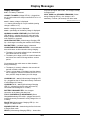
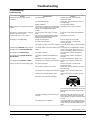
Display Messages
0.0V—
no battery is detected.
CONNECT CLAMPS
(Voltage LED lit)— plugged into
the AC outlet without the clamps connected to a 6 or 12
V battery.
xx.xV—
battery voltage is displayed.
----—
battery percentage is not yet available (starting
voltage is below 8.0 V).
xx.xA—
charging current is displayed.
xxo/o—
percentage of the battery charge is displayed.
WARNING-CLAMPS REVERSED
(Red REVERSED
LED ashing)— plugged into the AC outlet and with
battery clamps connected backwards. Display scrolls
until condition is corrected.
ANALYZING BATTERY
(Yellow/orange Charging LED
lit)— the charger is checking the condition of the battery.
BAD BATTERY—
a sulfated battery is detected.
CHARGE ABORTED-BAD BATTERY—
circumstances
that could cause an Abort situation during charging:
● The battery is severely sulfated or has a shorted cell
and cannot reach a full charge.
● The battery is too large or there is a bank of batteries
and it does not reach full charge within a set time
period.
Circumstances that could cause an Abort situation
during maintaining:
● The battery is severely sulfated or has a weak cell
and will not hold a charge.
● There is a large draw on the battery and the charger
has to supply its maximum maintain current for a 12
hour period to keep the battery at a full charge.
CHARGING 6 V – xxo/o
(Yellow/orange Charging LED
lit)— plugged into the AC outlet and correctly connected
to a discharged 6 V battery.
CHARGING 12 V – xxo/o
(Yellow/orange Charging
LED lit)— plugged into the AC outlet and correctly
connected to a discharged 12 V battery.
BATTERY DISCONNECTED—
the chargers
connection to the battery has been lost.
FULLY CHARGED-AUTO MAINTAINING
(Green
Charged/Maintaining LED solid)— plugged into the AC
outlet and correctly connected to a fully charged 6 or 12
V battery.
BOOST ON
(Yellow/orange Charging LED lit)— the
charger is in Boost mode.
ENGINE START ON
— shows during the rst 2 minutes
of Engine Start mode.
READY
(Yellow/orange Charging LED lit)— shows after
2 minutes in Engine Start mode. The charger is ready
for Engine Start.
COOL DOWN xxx SECONDS REMAINING
(Yellow/
orange Charging LED lit)— the charger is in a
mandatory 3 minute (180 second) cool down state.
MM95366,00003D6-19-26OCT18
Display Messages
25-1
La page est en cours de chargement...
La page est en cours de chargement...
La page est en cours de chargement...
La page est en cours de chargement...
La page est en cours de chargement...
La page est en cours de chargement...
La page est en cours de chargement...
La page est en cours de chargement...
La page est en cours de chargement...
La page est en cours de chargement...
La page est en cours de chargement...
La page est en cours de chargement...
La page est en cours de chargement...
La page est en cours de chargement...
La page est en cours de chargement...
La page est en cours de chargement...
La page est en cours de chargement...
La page est en cours de chargement...
La page est en cours de chargement...
La page est en cours de chargement...
La page est en cours de chargement...
La page est en cours de chargement...
La page est en cours de chargement...
La page est en cours de chargement...
La page est en cours de chargement...
La page est en cours de chargement...
La page est en cours de chargement...
La page est en cours de chargement...
La page est en cours de chargement...
La page est en cours de chargement...
La page est en cours de chargement...
La page est en cours de chargement...
La page est en cours de chargement...
La page est en cours de chargement...
La page est en cours de chargement...
La page est en cours de chargement...
-
 1
1
-
 2
2
-
 3
3
-
 4
4
-
 5
5
-
 6
6
-
 7
7
-
 8
8
-
 9
9
-
 10
10
-
 11
11
-
 12
12
-
 13
13
-
 14
14
-
 15
15
-
 16
16
-
 17
17
-
 18
18
-
 19
19
-
 20
20
-
 21
21
-
 22
22
-
 23
23
-
 24
24
-
 25
25
-
 26
26
-
 27
27
-
 28
28
-
 29
29
-
 30
30
-
 31
31
-
 32
32
-
 33
33
-
 34
34
-
 35
35
-
 36
36
-
 37
37
-
 38
38
-
 39
39
-
 40
40
-
 41
41
-
 42
42
-
 43
43
-
 44
44
-
 45
45
-
 46
46
-
 47
47
-
 48
48
-
 49
49
-
 50
50
-
 51
51
-
 52
52
-
 53
53
-
 54
54
-
 55
55
-
 56
56


Schumacher John Deere TY27732 Automatic Benchtop Starter/Charger Le manuel du propriétaire
- Catégorie
- Chargeurs de batterie de voiture
- Taper
- Le manuel du propriétaire
dans d''autres langues
Documents connexes
-
Schumacher SPI6 Automatic Battery Charger Le manuel du propriétaire
-
-
-
Schumacher FR01335 Automatic Battery Charger Le manuel du propriétaire
-
Schumacher FR01335FR01335 Le manuel du propriétaire
-
-
-
-
-
Autres documents
-
Matco Tools USM18A Manuel utilisateur
-
Motomaster 011-1504-0 Le manuel du propriétaire
-
Associated Equipment 6002B Manuel utilisateur
-
Defiant HD-997-5 Guide d'installation
-
 John Deere TY25864 Manuel utilisateur
-
 John Deere TY25862 Manuel utilisateur
-
Total TBC1601 Le manuel du propriétaire
-
 EMTOP EFCR16011 Le manuel du propriétaire


