
03/04 P/N 214573
1
Toll-Free Customer Service Number for U.S: 1-800-558-5234,
For Canada: 1-800-284-8339,
For Europe: 00 800 555 85234 (Sweden: 009 555 85234),
For Australia: 1-800-632-792
Internet Address: www.huffysports.com
HU
FFY
HUFFY
S
P
O
R
T
S
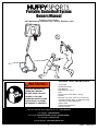
REQUIRED TOOLS AND MATERIALS:
• Two People
• Wood Board (Scrap)
• Tape Measure
• Step Ladder 8 ft. (2.4 m)
• Tape
• Garden Hose or Sand 360 lb. (163 kg)
• Hammer
• Wrenches: (Two) 3/4”, (One) 1/2” (Two) 9/16”or
equivalent sockets, (One) 1/2” Deep well socket
with extension and socket wrench
• Support Table
• Phillips Head Screwdriver
• 5/32 Allen Wrench
Portable Basketball System
Owners Manual
Customer Service Center
• N53 W24700 South Corporate Circle • Sussex, WI 53089 • U.S.A.
READ AND UNDERSTAND
OPERATOR'S MANUAL
BEFORE USING THIS UNIT.
FAILURE TO FOLLOW
OPERATING INSTRUCTIONS
COULD RESULT IN INJURY
OR DAMAGE TO PROPERTY.
WARNING!

2
P/N 214573 03/04
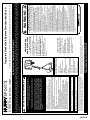
WARNING
FAILURE TO FOLLOW THESE WARNINGS MAY RESULT
IN SERIOUS INJURY AND/OR PROPERTY DAMAGE.
Owner must ensure that all players know and follow
these rules for safe operation of the system.
• DO NOT HANG on the rim or any part of the system
including backboard, support braces or net.
• During play, especially when performing dunk type
activities, keep player's face away from the backboard, rim
and net. Serious injury could occur if teeth/face come in
contact with backboard, rim or net.
• Do not slide, climb, shake or play on base and/or pole.
• After assembly is complete, fill system completely with
water or sand and stake to the ground. Never leave system
in an upright position without filling base with weight, as
system may tip over causing injuries.
• When adjusting height or moving system, keep hands and
fingers away from moving parts.
• Do not allow children to move or adjust system.
• During play, do not wear jewelry (rings, watches, necklaces,
etc.). Objects may entangle in net.
• Surface beneath the base must be smooth and free of
gravel or other sharp objects. Punctures cause leakage and
could cause system to tip over.
• Keep organic material away from pole base. Grass, litter,
etc. could cause corrosion and/or deterioration.
• Check pole system for signs of corrosion (rust, pitting,
chipping) and repaint with exterior enamel paint. If rust has
penetrated through the steel anywhere, replace pole
immediately.
• Check system before each use for proper ballast, loose
hardware, excessive wear and signs corrosion and repair
before use.
• Check system before each use for instability.
• Do not use system during windy and/or severe weather
conditions; system may tip over. Place system in the
storage position and/or in an area protected from the wind
and free from personal property and/or overhead wires.
• Never play on damaged equipment.
• See instruction manual for proper installation and
maintenance.
• When moving system, use caution to keep mechanism from
shifting.
• Keep pole top covered with cap at all times.
• Do not allow water in tank to freeze. During sub-freezing
weather add non-toxic antifreeze, sand or empty tank
completely and store. (Do not use salt.)
•
While moving system, Do not allow anyone to stand or sit
on base or have added ballasting on base.
• Do not leave system unsupervised or play on system when
wheels are engaged for moving.
• Use Caution when moving system across uneven surfaces.
System may tip over.
• Use extreme caution if placing system on sloped surface.
System may tip over more easily.
201246 2/99
In the U.S.:1-800-558-5234 and Canada: 1-800-284-8339

03/04 P/N 214573
3
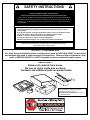
IMPORTANT!
Remove all contents from boxes.
Be sure to check inside pole sections;
hardware and additional parts are packed inside.
NOTICE TO ASSEMBLERS
ALL Huffy Sports basketball systems, including those used for DISPLAYS, MUST be assembled
and ballasted with sand or water according to instructions. Failure to follow instructions could
result in SERIOUS INJURY. It is NOT acceptable to devise a makeshift weight system.
SAFETY INSTRUCTIONS
FAILURE TO FOLLOW THESE SAFETY INSTRUCTIONS MAY RESULT IN SERIOUS INJURY OR
PROPERTY DAMAGE AND WILL VOID WARRANTY.
Owner must ensure that all players know and follow these rules for safe operation of the system.
To ensure safety, do not attempt to assemble this system without following the instructions carefully. Proper
and complete assembly, use, and supervision are essential for proper operation and to reduce the risk of
accident or injury. A high probability of serious injury exists if this system is not installed, maintained, and
operated properly.
• If using a ladder during assembly, use extreme caution.
• Check base regularly for leakage. Slow leaks could cause the system to tip over
unexpectedly
• Seat the pole sections properly (if applicable). Failure to do so could allow the pole
sections to seperate during play and/or during transport of the system.
• Climate, corrosion or misuse could result in system failure.
• If technical assistance is required, contact Huffy Sports.
• Minimum operational height is 6'-6" (1.98m) to the bottom of backboard.
Most injuries are caused by misuse and/or not following instructions.
Use caution when using this unit.
WARRANTY CARD:
Please remember to complete your product
registration form either on-line at:
www.huffysports.com/warrantycard or mail-in
the enclosed postcard.

4
P/N 214573 03/04
WARRANTY CARD:
Please remember to complete your product
registration form either
on-line at:
www.huffysports.com/warrantycard
or mail-in the enclosed postcard.
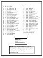
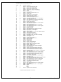
PARTS LIST (See Hardware Identifier)
Item Qty. Part No. Description
1 1 900149 Top Pole Section, Black
2 1 904811 Middle Pole Section, Black
3 1 903407 Bottom Pole Section, Black
4 1 200188 Rod, Zinc 3/8 x 5-1/4 Long
5 1 202822 Eyebolt, 3/8–16 x 3-3/4 Long
6 1 200117 Base
7 1 203124 Stake, Tie Down
8 4 203063 Lock Nut, Nylon Insert, 3/8–16
9 2 906410 Struts, Base
10 1 202662 Bolt, 5/16-18 x 4-1/2 Long
11 7* 203218 Washer, Flat, 5/16 x 7/8 O.D.
12 1 203220 Lock Nut, Nylon Insert, 5/16-18
13 1 200516 Vinyl, Bolt Cover, 5/16
14 2 203798 Bolt, Hex Flange, 5/16-18 x 1-1/2 Long
15 20* 203100 Lock Nut, Whiz, 5/16-18
16 1 203223 Bolt,Carriage 5/16-18 X 1.00” Long
17 2 226401 Wheel 4” Diameter
18 1 200123 Upper Pivot Bracket
19 1 200512 Bolt, Hex Head,3/8-16 x 3-1/2 Long
20 9* 203232 Washer, 3/8 I.D., x 3/4 O.D.
21 1 206252 Bolt, Hex Head, 3/8-16 x 1 Long
22 1 206948 Lower Pivot Bracket
23 1 203330 Bolt, Hex Head, 3\8-16 x 4-1/2 Long
24 2 200122 Hinge Tubes
25 2 900223 Wheel Bracket
26 6 203103 Bolt, Carriage, 5/16-18 x 2 Long
27 2 226403 Wheel 6” Diameter
28 2 206940 Axle, .461 O.D. x 21 Long
29 4 206938 Push Caps
30 1 206956 Disc, Plastic, 5” O.D. x .0625 Thick
31 1 904866 Height Adjustment Rod
32 2 204858
Spacer, Plastic, Biscuit
33 2* 204857
Spacer, Metal 1/2” O.D. x 1.44 Long
34 1 204853 Lanyard, Black Coil
35 1 204850 Pin, Locking
36 1 204803
Screw, Phillips Head
37 3 201124 Lock Nut, Hex, 3/8-16
38 1 204855 Handle, Left
Item Qty. Part No. Description
39 1 204856 Handle, Right
40 1 200118 Front Cover
41 1 204872 Label, Height Indicator
42 1 206219 Cap, Base-Black
43 1 203814 Label, Height and Moving
44 1 201568 Anchor Strap
45 1 204832 Bracket, Pole Mount
46 2 203053 Bolt, Carriage, 5/16-18 x 4 Long
47 1 206990 Reinforcement Bracket
48 2 204859 Cover
49 2 200533 Board Spacer
50 1 203038 Bolt, Carriage, 5/16-18 x 2.75" Long
51 2 201129 Spacer, Metal, .5 O.D. x .402 I.D. x 1.8 Long
52 2 900846 Board Bracket
53 1 240017 Bolt, Hex Head, 1/4-20 x 2-1/4 Long
54 3 206360 Bolt, Hex Head, 3/8-16 x 2.625 Long
55 1 203493 Lock Nut, Hex Center-lock, 1/4-20
56 2 900183 Elevator Tube, Lower (Long)
57 6 204847 Bolt, Hex Head, 1/2-13 x 9-1/2 Long
58 7 206340 Lock Nut, 1/2-13
59 4 201682 Spacer, Black, .56 I.D. x .683 O.D. x 1.88 Long
60 4 201611 Bolt, Hex Flange, 5/16-18 x 3 Long
61 4 265601 Bolt, Carriage, 5/16-18 x 3-1/2 Long
62 4* 205528 Bolt, Hex Flange, 5/16-18 x 1 Long
63 2 904807 Elevator Tubes, Upper (Short)
64 1 207103 Pole Cap
65 1 201139 Bolt, Hex Head, 1/2-13 x 4-1/2 Long
66 2 900867 Triangle Plate
67 8 202862 Spacer, Plastic, 1/2 I.D., 1-1/4 Long
68 1 204837 Spring
69 1 Net
70 1 Rim
71 12 201219 Smart Clip, Net Holder
*You may have extra parts with this model
WARNING: IF YOUR SYSTEM IS EQUIPPED WITH AN ACRYLIC
BACKBOARD, EXAMINE BACKBOARD FOR ANY DAMAGE THAT MAY
HAVE OCCURRED DURING SHIPMENT. CRACKS IN THE BACKBOARD
COULD RESULT IN SUDDEN BREAKAGE. IF BACKBOARD IS
DAMAGED IN ANY WAY PRIOR TO OR AFTER ASSEMBLY, CALL TOLL-
FREE NUMBER FOR FREE REPLACEMENT:
U.S. 1-800-558-5234; CANADA: 1-800-284-8339;
http://www.huffysports.com

03/04 P/N 214573
5
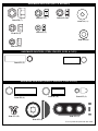
HARDWARE IDENTIFIER (CONTINUED)
HARDWARE IDENTIFIER (BOLTS & SCREWS)
Item #5 (1)
Item #21 (1)
Item #26 (6)
Item #19 (1)
Item #53 (1)
Item #50 (1)
Item #65 (1)
Item #46 (2)
Item #54 (3)
Item #61 (4)
Item #23 (1)
Item #10 (1)
Item #36 (1)
Item #14 (2)
Item #16 (1)
Item #62 (4)*
Item #60 (4)
Item #50 (6)

6
P/N 214573 03/04
*You may have extra parts with this model.
HARDWARE IDENTIFIER (NUTS & WASHERS)
HARDWARE IDENTIFIER (STEEL SPACERS, RODS & CLIPS)
HARDWARE IDENTIFIER (PLASTIC SPACERS, CAPS & CLIPS)
Item #37 (3)*
Item #55 (1)
Item #58 (7)
Item #51 (2)
Item #67 (8)
Item #71 (12)
Item #59 (4)
Item #20 (8)*
Item #11 (7)*
Item #15 (20)*
Item #8 (4)
Item #12 (1)
Item #13 (1)
Item #32 (2)
Item #33 (2)*
Item #29 (4)

03/04 P/N 214573
7
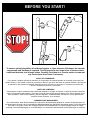
BEFORE YOU START!
To ensure optimal playability of backboard system, a close tolerance fit between the elevator
components and hardware is required. Test-fit large bolts into large holes of elevator tubes,
backboard brackets, and triangle plates. Carefully rock them in a circular motion to ream out
any excess paint from holes if necessary.
AVANT DE COMMENCER !
Pour garantir l'utilisation optimale du panneau, les composants du système élévateur et la visserie doivent être bien
ajustés (serrés). À titre d'essai, insérez les gros boulons dans les gros trous des tubes du système élévateur, des supports
du panneau et des plaques triangulaires. Basculez-les avec précaution en imprimant un mouvement circulaire pour
éliminer l'excédent de peinture, si nécessaire.
¡ANTES DE COMENZAR!
Para asegurar el óptimo rendimiento del sistema del respaldo en el juego, se requiere un ajuste de tolerancia estrecha
entre los componentes del elevador y el herraje. Pruebe el ajuste de los pernos grandes en los orificios grandes de los
tubos elevadores, soportes del respaldo y placas triangulares. Cuidadosamente muévalos en círculos para eliminar
cualquier exceso de pintura, si es necesario.
VORBEREITENDE MASSNAHMEN
Um sicherzustellen, dass das Korbwandsystem optimal für den Spielbetrieb geeignet ist, müssen die Komponenten der
Verlängerungsvorrichtung und die verschiedenen Befestigungsteile fest miteinander verschraubt werden. Große Schrauben
zur Probe in die großen Löcher der Verlängerungsrohre, Korbwandklammern und Dreiecksplatte stecken und diese
vorsichtig in einer Kreisbewegung hin- und herbewegen, um eventuelle Farbrückstände aus den Bohrungen zu entfernen.

8
P/N 214573 03/04
2
3
1
3.
2.
1.
Wood Scrap
2
1
5"
(13 cm)
MIDDLE
TOP
5"
(13 cm)
BOTTOM
2
3
1
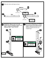
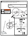
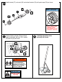
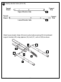
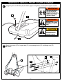
Mark pole sections with tape as shown.
TAPE
(not supplied)
TAPE
(not supplied)
IMPORTANT! Bounce pole top (1) and
middle section (2) together as shown until
they no longer move toward taped
reference mark. Upright assembly.
POLE SECTIONS
SHOULD HAVE A
3-1/2" (9 CM)
MINIMUM OVERLAP.
NOTE:
IMPORTANT! Holes in top (1) and bottom
pole (3) sections MUST align to correctly
position elevator system toward playing
surface. Add bottom pole section (3) to
assembly as shown and bounce until
completely tight.
POLE SECTIONS
SHOULD HAVE A
3-1/2" (9 CM)
MINIMUM OVERLAP.
NOTE:

03/04 P/N 214573
9
4.
5.
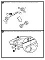
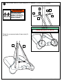
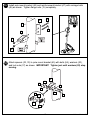
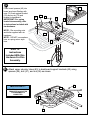
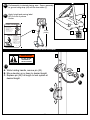
Install wheels (17) onto axle (28) and wheel bracket (25) with push caps (29) as shown.
Position base as shown. Secure wheel bracket assembly with bolt (16) and nut (15) as shown.
25
17
17
29
29
28
15
16
15

10
P/N 214573 03/04
6.
Install rod (4) through holes in bottom pole section (3) and eyebolt (5).
Insert pole assembly into tank (6) and through center hole on wheel assembly as shown. Secure
pole assembly with strap (44), washer (11) and lock nut (8).
5
4
1
3
2
8
TWO PEOPLE REQUIRED
FOR THIS PROCEDURE.
FAILURE TO FOLLOW THIS
WARNING COULD RESULT IN
SERIOUS INJURY AND/OR
PROPERTY DAMAGE.
WARNING!
8
4
5
11
44

03/04 P/N 214573
11
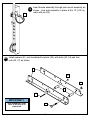
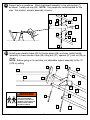
7.
9
9
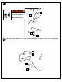
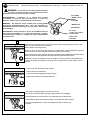
Secure base struts (9) to pole using bolt (10) washers (11) and nut (12) as shown.
Rotate the non-secured ends of base struts (9)
as shown.
TWO PEOPLE REQUIRED
FOR THIS PROCEDURE.
FAILURE TO FOLLOW THIS
WARNING COULD RESULT IN
SERIOUS INJURY AND/OR
PROPERTY DAMAGE.
WARNING!
10
11
11
12
9
3
13
NOTE:
ORIENTATION OF STRUTS

12
P/N 214573 03/04
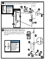
8.
9.
Secure base struts (9) to base using bolt (14) washers (11) and nut (15).
Install upper pivot bracket (18) to front of base using bolt (19), washer (20) and nut (8) as shown.
14
11
15
11
9
8
20
18
19
TWO PEOPLE REQUIRED
FOR THIS PROCEDURE.
FAILURE TO FOLLOW THIS
WARNING COULD RESULT IN
SERIOUS INJURY AND/OR
PROPERTY DAMAGE.
WARNING!

03/04 P/N 214573
13
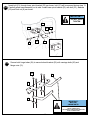
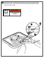
Insert bolt (21) through lower pivot bracket (22) as shown, bolt (21) will be secured during step 13.
Carefully place base assembly on its side. Install lower pivot bracket (22) with bolt (23), washers
(20) and lock nut (8) as shown.
Secure both hinge tubes (24) to second wheel bracket (25) with carriage bolts (26) and
flange nuts (15).
18
23
20
22
21
20
8
26
25
15
24
10.
11.
IMPORTANT!:
DO NOT OVER
TIGHTEN
IMPORTANT!:
WICHTIG!:
¡IMPORTANTE!:
NOTE ORIENTATION
NOTEZ L'ORIENTATION.
DIE KORREKTE AUSRICHTUNG BEACHTEN.
NOTE LA ORIENTACIÓN.

14
P/N 214573 03/04
Position base as shown. Secure wheel
bracket assembly with disc (30), washer
(20) and nut (8) as shown.
29
27
28
25
27
29
21
30
20
8
Carefully reposition entire
assembly as shown:
12.
13.
SIDE OF WHEEL WITH
LONGER PLASTIC
AXLE NEEDS TO FACE
THE WHEEL BRACKET.
IMPORTANT!:
TWO PEOPLE REQUIRED
FOR THIS PROCEDURE.
FAILURE TO FOLLOW THIS
WARNING COULD RESULT IN
SERIOUS INJURY AND/OR
PROPERTY DAMAGE.
WARNING!
Install wheels (27) onto axle (28) and wheel bracket (25) with push caps (29) as shown.
IMPORTANT!:
DO NOT OVER
TIGHTEN
14.

03/04 P/N 214573
15
15.
Install pole mount bracket (45) and reinforcement bracket (47) with carriage bolts
(46) as shown. Tighten flange nuts (15) completely.
1
45
15
15
47
46
46
16.
Attach spacers (32, 33) to pole mount bracket (45) with bolts (54), washers (20),
and lock nuts (37) as shown. IMPORTANT! Tighten just until washers (20) stop
moving.
45
20
20
37
54
20
20
33
32
32
33

16
P/N 214573 03/04
17.
45
15
35
48
48
34
50
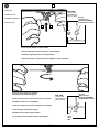
Apply logo and height indicator labels (41) to
adjustment rod (31) as shown. Attach handle
parts (38, 39) to adjustment rod with screw
(36), carriage bolts (26), and flange nuts (15)
as shown.
18.
26
15
15
39
38
36
26
31
41
41
Assemble lanyard (34) to locking pin (35) as shown (FIG A). Attach covers (48) onto
pole mount bracket (45) with carriage bolt (50) and nut (15) as shown.
50
FIG. A
34
35
Loop end of pin
lanyard (34) over
carriage bolt (50)
as it passes
through the pole
mount bracket
(45) during this
assembly.
IMPORTANT!:
Indicator labels
should be applied
as close to holes
as possible to
prevent labels from
being damaged
during height
adjustment.
IMPORTANT!:

03/04 P/N 214573
17
Insert handle assembly through pole mount assembly as
shown. Lock pole assembly in place at the 10’ (3.05 m)
mark with pin (35).
35
19.
20.
53
51
37
54
52
55
Install spacers (51) onto backboard brackets (52), with bolts (53, 54) and lock
nuts (55, 37) as shown.
IMPORTANT!:
KEEP HARDWARE LOOSE
UNTIL AFTER STEP 25 IS
COMPLETED.

18
P/N 214573 03/04
21.
Attach lower elevator tubes (56) and counter balance spring (68) to backboard
support brackets (52) using spacers (59), bolt (57), and nut (58) as shown.
63
Upper Elevator tube
Toward
Pole
Toward
Board
56
Lower Elevator tube
Toward
Pole
Toward
Board
Identify elevator tubes (63 & 56).
56
58
59
57
56
52
68
59

03/04 P/N 214573
19
22.
Place board spacers (49) into
board as shown.Starting with
nuts (15) flush against bracket
(52) secure rim (70) and
bracket to backboard.
IMPORTANT! For spring
loaded rim assembly, refer
to instructions included with
rim hardware.
NOTE: Rim mounting nuts
and bolts supplied with rim
hardware.
NOTE: DO NOT use washers
here on spring return style
rims.
58
57
59
59
63
63
52
Refer To
Instructions
Included With Rim
Hardware For Rim
Assembly.
23.
Attach upper elevator tubes (63) to backboard support brackets (52) using
spacers (59), bolt (57), and nut (58) as shown.
IMPORTANT!:
TIGHTEN ALL HARDWARE
FROM STEP 22-25 AFTER
THIS ASSEMBLY IS
COMPLETED.
62
70
62
62
62
15
49
49
52

20
P/N 214573 03/04
58
58
65
64
56
1
66
66
57
67
56
67
24.
Support pole on sawhorse. Attach backboard assembly to top pole section (1)
as shown. Install pole cap (64). NOTE: Two people are recommended for this
step. Use caution; elevator assembly is heavy.
57
63
67
58
1
58
63
67
66
51
25.
Install upper elevator tubes (63) to triangle plates (66) as shown. Install handle
assembly to lower elevator tubes (56) using bolt (57), spacers (67), and nut (58) as
shown.
NOTE: Before going on to next step, set adjustable system assembly to the 10’
(3.05 m) setting.
57
56
56
67
67
TWO PEOPLE REQUIRED
FOR THIS PROCEDURE.
FAILURE TO FOLLOW THIS
WARNING COULD RESULT IN
SERIOUS INJURY AND/OR
PROPERTY DAMAGE.
WARNING!
La page est en cours de chargement...
La page est en cours de chargement...
La page est en cours de chargement...
La page est en cours de chargement...
La page est en cours de chargement...
La page est en cours de chargement...
La page est en cours de chargement...
La page est en cours de chargement...
La page est en cours de chargement...
La page est en cours de chargement...
La page est en cours de chargement...
La page est en cours de chargement...
La page est en cours de chargement...
La page est en cours de chargement...
-
 1
1
-
 2
2
-
 3
3
-
 4
4
-
 5
5
-
 6
6
-
 7
7
-
 8
8
-
 9
9
-
 10
10
-
 11
11
-
 12
12
-
 13
13
-
 14
14
-
 15
15
-
 16
16
-
 17
17
-
 18
18
-
 19
19
-
 20
20
-
 21
21
-
 22
22
-
 23
23
-
 24
24
-
 25
25
-
 26
26
-
 27
27
-
 28
28
-
 29
29
-
 30
30
-
 31
31
-
 32
32
-
 33
33
-
 34
34


Huffy 2145731 Manuel utilisateur
- Taper
- Manuel utilisateur
- Ce manuel convient également à
dans d''autres langues
- español: Huffy 2145731 Manual de usuario
- Deutsch: Huffy 2145731 Benutzerhandbuch
Documents connexes
-
Huffy Sports Basketball Systems Manuel utilisateur
-
-
-
-
-
-
-
-
-
Spalding 214994B Manuel utilisateur