SportsArt T655MD Le manuel du propriétaire
- Catégorie
- Tapis de course
- Taper
- Le manuel du propriétaire

T655MD OWNER’S MANUAL CONTENTS
1. INTRODUCTION ................................................................................ 2
2. SAFETY PRECAUTIONS .................................................................. 4
3. LIST OF PARTS ................................................................................. 9
4. ASSEMBLE THE PRODUCT ............................................................. 11
STEP 0 Preparation: Separate product from the Package .................... 11
STEP 0 Preparation: Inspect Walk Belt Placement ............................... 12
STEP 1 Install the Pedestals and Display ............................................. 13
STEP 2 Install the Right/Left Side Covers ............................................ 20
STEP 3 Install Long Handrails .............................................................. 21
STEP 4 Install Handlebars .................................................................... 25
STEP 5 Install Handrail Front/Rear Covers .......................................... 26
STEP 6 Install Screw Head Covers ...................................................... 27
STEP 7 Apply Height Stickerl .............................................................. 28
STEP 8 How to Move the Treadmill ...................................................... 29
STEP 9 Level the Treadmill .................................................................. 30
STEP 10 Align the Walk Belt ................................................................. 31
STEP 11 Adjust Walk Belt Tightness ..................................................... 33
STEP 12 Install the Power Cord ............................................................ 34
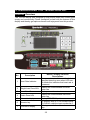
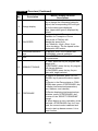
5. UNDERSTAND THE T655MD DISPLAY ........................................... 35
DISPLAY Overview ............................................................................... 35
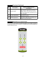
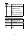
DISPLAY Wired Remote Control Panel ................................................ 37
DISPLAY Specications ........................................................................ 38
6. OPERATE THE PRODUCT .............................................................. 39
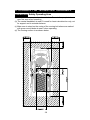
OPERATION Safety Operating Area .................................................... 39
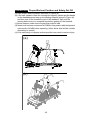
OPERATION Proper Workout Position and Safety Get Off .................. 40
OPERATION Optional Step Safety Get On/Off .................................... 41
OPERATION Safety Mechanism Activation & Reactivation ................. 42
OPERATION Operate the Product ....................................................... 44
OPERATION Quick Start ...................................................................... 45
OPERATION Start a Workout Program ................................................ 45
OPERATION Display ............................................................................ 46
OPERATION Cool Down ...................................................................... 46
OPERATION Idle Mode ........................................................................ 46
OPERATION Workout Programs .......................................................... 47
OPERATION User Preference and Component Versions .................... 47
7. ABOUT HEART RATE DETECTION ................................................ 49
HEART RATE Telemetry ...................................................................... 49
8. GUIDELINES FOR EXERCISE ........................................................ 50

T655MD OWNER’S MANUAL CONTENTS
9. MAINTENANCE ............................................................................... 51
MAINTENANCE Safety Precautions ................................................... 51
MAINTENANCE Error Messages ....................................................... 52
MAINTENANCE Circuit Breaker ......................................................... 53
MAINTENANCE Lubrication System ................................................... 54
MAINTENANCE Schedule ................................................................... 57
MAINTENANCE Task List .................................................................... 58
MAINTENANCE One-Year Maintenance Log ...................................... 59
10. ACCESSORIES ............................................................................. 60
ACCESSORIES Entertainment Cap .................................................... 61
ACCESSORIES Options ..................................................................... 62
11. APPENDIXES ................................................................................. 63
APPENDIXES Specications ................................................................ 63
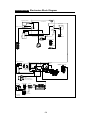
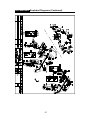
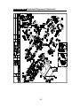
APPENDIXES Electronics Block Diagram ............................................ 64
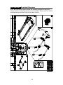
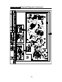
APPENDIXES Exploded Diagrams........................................................ 65
*We reserve the right to revise this manual at any time without notice.

2
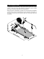
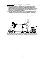
1. INTRODUCTION
Congratulations on the purchase of a high quality SportsArt product, the T655MD
treadmill. Constructed of high quality materials and designed for years of reliable
performance, this product was made for full commercial use.
Before this product is assembled or operated, we recommend that you familiarize
yourself with this manual. Understanding the correct assembly and operation of
this product will help ensure that exercisers obtain their tness goals safely and
successfully.
L
R

3
1. INTRODUCTION (CONTINUED)
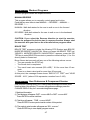
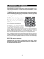
1.1 Product Descriptions
T655MD is a treadmill for medical & rehabilitation use. It integrates adjustable speed
and slope control. It also allows users to walk in forward & backward directions, thus
training users to regain or improve walking/running ability. Bilateral handrails assist
patients to walk/run safely.
1.2 Intended Use
1. Enhance cardiovascular tness and lower extremity functional ability.
2. Extremely low speed is suitable for gait training, endurance training, and
rehabilitation training.
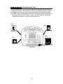
3. Combined use of external device and T655MD, the treadmill can be a loading
device for ECG measuring of rehabilitation users with chronic and physical
disabilities during training session.
4. Combining T655MD with external devices an electrical system is created.
The responsibility rests with the manufacturer of electrical system, but not with
SPORTSART.
1.3 Indication for use
Joint replacement, Rheumatoid arthritis, Osteoarthritis, Stiff person syndrome,
Multiple sclerosis, Traumatic brain injury, Lower limbs ligament sprain and
Stroke.
1.4 Application areas
Rehabilitation facilities, physical therapy clinics, nursing homes, hospitals, senior
centers, assisted living settings.
1.5 Operating principle
The motor-driven treadmill replicate human walking at various gait speeds. It could
stimulate the patient’s lower limb muscles, thus to regain better control of lower limb,
and enhance lower limb blood circulation. In this way the ability of lower limb muscle
group, physical strength, and basic control ability of the patient can be rehabilitated
gradually.
1.6 Restriction of Liability
The T655MD may be operated only in medical facilities by medical staff. T655MD
must not be operated in home environment.
The correct loading for a patient on the T655MD must be prescribed by a
medical doctor. The T655MD manufacturer cannot make any declaration or
recommendation.

4
2. SAFETY PRECAUTIONS
This product was designed and built for optimum safety. However certain precau-
tions apply during the use of this product. Please note the following safety
precautions:
• Please read the entire manual before assembly and operation. Make
sure the product is installed and operated as instructed in this manual.
• Assemble and operate the product on a solid, level surface. Do not use
outdoors or near water, including pools and saunas.
• Check the product before every use. Make sure all parts are assem-
bled, and all fasteners are tightened. Do not use the product if it is disas-
sembled in any way.
• Wear proper workout clothing. Do not wear loose clothing. Do not wear
shoes with leather soles or high heels. Tie all long hair back. Do not go
barefoot on this product.
• Keep away from moving parts. Moving parts may or may not stop imme-
diately if an object becomes caught or impedes normal motion.
• Use this product only for its intended purpose as described in this
manual.
• Be careful when mounting and dismounting the unit.
• Never operate this product if it has been damaged in any way. If it is
not working properly, or has been dropped or damaged, contact a service
technician for repairs.
• Do not use accessories or parts that are not specically recommended
by the manufacturer (SportsArt). Such parts might cause injuries or cause
the unit to fail and void the warranty. We are not responsible for any safety
issue that arises due to the misuse of accessories or parts. At the same
time, we will terminate the warranty terms of this equipment.
• Keep all air ventilation areas free of blockage. Never drop or insert any
object into any opening.
• Do not operate where aerosol (spray) products are being used or where
oxygen is being administered.
• This product is not intended for use by persons (including children 12
or younger) with reduced physical, sensory, or mental capabilities, or by
people who are otherwise decient in product knowledge or experience. If
such people use this product, they should be given training and be super-
vised at all times by someone responsible for their safety.
• Contact your SportsArt representatives on all materials damaged in
shipment. (Note: Shipping damages are the responsibility of the carrier.)
• Unpack and verify contents of boxes according to the list of parts to
check if any parts are missing.
• Children 12 or younger should be supervised to ensure that they do not
play on or near the product.
• Treadmills should be positioned away from walls to avoid injury due to
falls. Be sure that the back of the treadmill has at least six to seven feet of
clearance from a ledge, wall or window. The power supply and wiring should
be located away from walking paths or taped to prevent tripping when step-
ping on or off of the running belt.
• Close supervision is necessary when this treadmill is used by, on, or near
children 12 or younger, invalids, or disabled persons
• The user weight limit for this product is 180 kg, 400 lb. At maximum
speed, this product meets standards for users up to 136 kg, 300 lb.

5
2. SAFETY PRECAUTIONS (CONTINUED)
CAUTION: If you feel any pain or any abnormal sensations, STOP YOUR
WORKOUT and consult your physician immediately. Work within your
recommended exercise level. DO NOT work to exhaustion. Before beginning
any exercise program, you should consult with your doctor. It is recommended that
you undergo a complete physical examination.
CAUTION: If you select the Reverse direction to start the exercise, please be
prepared for belt to start in reverse direction. Always start the exercise with your feet
on the side rails before program starts.
WARNING! Heart rate monitoring systems may be inaccurate. Over exercise may
result in serious injury or death. If you feel faint, stop exercising immediately.
Note: This equipment has been tested and found to comply with the limits for a Class
B digital device, pursuant to part 15 of the FCC Rules. These limits are designed to
provide reasonable protection against harmful interference in a residential instal-
lation. This equipment generates, uses and can radiate radio frequency energy and,
if not installed and used in accordance with the instructions, may cause harmful
interference to radio communications. However, there is no guarantee that inter-
ference will not occur in a particular installation. If the user desires to correct the
interference, it is at the user’s own expense.
WARNING! Only qualied technicians should be allowed to contact electrical
components such as circuit boards. Some components carry an electrical charge
even after use has been discontinued or the product has been unplugged. For
products with power cords, turn off unit power, wait ve minutes, then disconnect
the power cord from the power socket. For products without power cords, let the unit
sit without use for ve minutes. Only after taking such precautions should covers be
removed and electrical components be accessed.
• Do not attempt to drag or carry this unit by the power cord. Keep the
power cord away from heated surfaces.
• Improper grounding can increase the risk of electric shock. Check with
a qualied electrician if you are in doubt as to whether the power outlet is
properly grounded.
• Do not attempt to modify the plug provided with this product. Proper pow-
er supply must be provided. If the plug does not t an outlet, contact a quali-
ed electrician to inspect or modify power in the facility.
• Do not stand on the walk belt when starting the treadmill. Straddle the
belt with your feet on the right and left landing strips.
• Always use the safety key when operating the treadmill.
• The treadmill should be disconnected from its power source during ser-
vice and when replacing parts.
• Maintenance and repair must be performed by trained service person-
nel only. Improper maintenance would not only damage the machine, but
may also present a danger to the exerciser.
• Warning that any of the adjustment devices that could interfere with the
user’s movement should not be left projecting.
CAUTION: If you select the Reverse direction to start the exercise, please
be prepared for belt to start in reverse direction. Always start the exercise
with your feet on the side rails before program starts.

6
2. SAFETY PRECAUTIONS (CONTINUED)
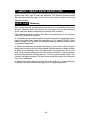
If you are a French speaking person in North America, please place the
following label contained in the owner’s manual on the console as shown.
Customers outside of North America will not receive this French warning
label.
(Note: If there are any other warning labels contained in the owner’s manual,
please place them on the clearly displayed location on the console as well.)

7
2. CONSIGNES DE SÉCURITÉ IMPORTANTES
Votre tapis de course SportsArt a été conçu et fabriqué afin d’assurer une sécurité
optimale. Cependant certaines précautions s’appliquent chaque fois que vous uti-
lisez votre tapis de course.
• Lisez entièrement le manuel avant l’assemblage et l’utilisation. Veuillez aussi
noter les consignes de sécurité suivantes:
• Veuillez lire attentivement les instructions et installer le tapis de course selon
les instructions.
• Assemblez et faites fonctionner l’elliptique sur une surface solide et plane; NE
PAS l’utiliser à l’extérieur ou près de l’eau.
• En aucun cas, ne laissez des enfants à proximité ou sur le tapis de course.
• Vériez le tapis de course avant chaque utilisation. Assurez-vous que toutes
les pièces sont assemblées et que tous les éléments de xation sont serrés. NE
PAS utiliser le tapis de course si l’appareil est démonté de quelque façon.
• Gardez vos mains loin des pièces mobiles.
• Portez des vêtements d’entraînement appropriés; NE PORTEZ PAS de vête-
ments amples. NE PORTEZ PAS de chaussures à semelles en cuir ou à talons
hauts. Attachez les cheveux longs. Ne marchez pas pieds nus sur l’appareil.
• Soyez prudent lors du montage et démontage de l’appareil.
• Le tapis de marche ne s’arrêtera pas immédiatement si un objet est pris dans
les courroies ou les rouleaux.
• NE PAS utiliser d’accessoire non spéciquement recommandé par le fabri-
cant. Car cela pourraient provoquer des blessures ou entraîner une panne de
l’appareil.
• Débranchez l’appareil de la prise avant l’entretien ou la suppression de toute
pièce.
• Une surveillance étroite est nécessaire quand ce tapis de course est utilisé par
ou à proximité d’enfants, de malades ou de personnes handicapées.
• Utilisez ce tapis de course uniquement pour l’usage prévu dans ce manuel.
• N’utilisez jamais ce tapis de course s’il a été endommagé de quelque façon
que ce soit. S’il ne fonctionne pas correctement, ou s’il est tombé ou endom-
magé, contactez votre vendeur.
• NE PAS transporter ce tapis de course par le cordon d’alimentation et
n’utilisez pas le cordon comme poignée.
• Maintenez le cordon éloigné de toute surface chaude.
• Veillez à ce qu’aucun orice de ventilation ne soit obstrué.
• Ne faites jamais tomber ou n’insérez jamais d’objet dans les orices.
• NE PAS l’utiliser là où des produits aérosols (vaporisés) sont utilisés ou
lorsque de l’oxygène est administré.
• La limite de poids de l’utilisateur pour ce tapis de course est de 227 kg, 500 lb.
Remarquez que la vitesse de 15 mph (24 km/h) convient jusqu’à 160 kg, 350 lb.
• Les performances du produit dépendent d’une alimentation adéquate.
• Ce tapis de course n’est pas destiné à être utilisé par des personnes (y com-
pris des enfants) dont les capacités physiques, sensorielles ou mentales sont
réduites ou qui ne disposent pas de l’expérience ou du savoir nécessaires, sauf
si celles-ci ont au préalable été formées eu égard à l’utilisation de ce tapis de
course par une personne responsable de leur sécurité.
• Les enfants doivent être encadrés an d’empêcher qu’ils ne jouent avec le
tapis de course.
• Les tapis de course doivent de préférence être situés loin des murs, pour éviter
de se blesser en cas de chute. Vérifiez si l’extrémité arrière du tapis est au moins à
2 mètres d’un rebord, d’un mur ou d’une fenêtre. Veillez également à positionner le
cordon d’alimentation loin de tout passage ou à le protéger avec du ruban adhésif
pour ne pas s’y prendre les pieds en montant et descendant du tapis.
• Utilisez toujours le clip de sûreté pendant le fonctionnement du tapis de
course.
• NE PAS rester sur le tapis de marche lors du démarrage du tapis de course.
Enjambez le tapis et placez vos pieds sur les bandes de repos droite et gauche.

8
• Pour éviter de vous blesser, restez sur les bandes de repos (barres latérales)
avant de démarrer le tapis de course.
• Ce tapis de course n’est pas destiné à être utilisé par des personnes (y com-
pris des enfants) dont les capacités physiques, sensorielles ou mentales sont
réduites ou qui ne disposent pas de l’expérience ou du savoir nécessaires, sauf
si celles-ci ont au préalable été formées eu égard à l’utilisation de ce tapis de
course par une personne responsable de leur sécurité.
• Les enfants doivent être encadrés an d’empêcher qu’ils ne jouent avec le
tapis de course.
• Utilisez toujours le clip de sûreté pendant le fonctionnement du tapis de
course.
• NE PAS rester sur le tapis de marche lors du démarrage du tapis de course.
Enjambez le tapis et placez vos pieds sur les bandes de repos droite et gauche.
• Pour éviter de vous blesser, restez sur les bandes de repos (barres latérales)
avant de démarrer le tapis de course.
ATTENTION
Si vous ressentez une douleur ou si vous avez une sensation anormale, AR-
RÊTEZ VOTRE ENTRAÎNEMENT et consultez immédiatement votre médecin.
Entraînez-vous à votre niveau d’exercice recommandé. NE PAS s’entraîner jusqu’à
l’épuisement.
• Avant de commencer un programme d’exercice, vous devriez consulter votre
médecin. Il est recommandé de faire un examen physique complet.
• NE PAS monter sur l’étape plus haute. En maintenant sur les supports de
stabilité, monter sur l’ étape plus bas.
• Pour diminuer le risque de choc électrique, débranchez toujours ce tapis de
course de la prise de courant, immédiatement après utilisation et avant le nettoy-
age.
• Un branchement incorrect du connecteur de mise à la terre de l'équipement
risque d'entraîner un choc électrique. En cas de doute sur la mise à la terre cor-
recte de l’elliptique, faites appel à un technicien ou un électricien qualié. NE
PAS modier la che fournie avec l’elliptique, si elle ne correspond pas à la prise,
faites installer une prise adéquate par un technicien qualié.
Remarque: Ce matériel a été testé et déclaré conforme aux normes des appareils
digitaux de Classe B, conformément à la partie 15 du Règlement de la FCC. Ces
limites sont conçues pour offrir une protection raisonnable contre les interférences
nuisibles dans une installation résidentielle. Cet appareil génère, utilise, et peut dif-
fuser des signaux radioélectriques, et, s’il n’est pas installé et utilisé conformément
aux instructions, peut provoquer des interférences nuisibles aux communications
radio. Cependant, il n’y a aucune garantie que des interférences ne se produiront
pas dans une installation particulière. Si l'utilisateur désire corriger les interférenc-
es, ces corrections seront à la charge de l’utilisateur
Dans ce manuel, les mots “gauche” et “droit” sont utilisés en référence aux pièces
et au produit. Comme tels, les mots “gauche” et “droit” font respectivement ré-
férence aux côtés gauche et droit de l’exerciseur. De même pour plus de conci-
sion, le mot «vis» est utilisé dans certains cas où des rondelles, des vis et autres
matériels sont associés.
Attention: Si vous sélectionnez le sens inverse pour commencer l’exercice, s’il
vous plaît soyez prêts au fait que la ceinture va démarrer dans le sens inverse.
Commencez toujours l’exercice avec vos pieds sur les rails latéraux avant que le
programme démarre.
2. CONSIGNES DE SÉCURITÉ (SUITE)

9
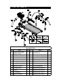
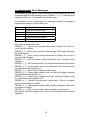
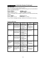
3. LIST OF PARTS
Assembly Parts
No. Name Qty. No. Name Qty.
A1
Display (With wired
remote control)
1 A10 Hardware kit 1
A2 Right pedestal 1 A11 Power cord 1
A3 Feeder cord 1 A12 French Sticker (For USA) 1
A4 Pedestal cover 2 A13 Right long handrail 1
A5 Water guard 2 A13a Right handlebar 1
A6 Main frame 1 A13b Left handlebar 1
A6a Right side cover 1 A14 Left long handrail 1
A6b Left side cover 1 A14a Handrail front cover A 2
A7 Support 1 A14b Handrail front cover B 2
A8 Left pedestal 1 A14c Handrail rear cover A 2
A9 Owner’s manual 1 A14d Handrail rear cover B 2

10
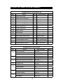
Components in the Hardware Kit
No. Name Qty. Specication Notes
31 Screw cover (at) 2
32 Screw cover (rounded) 4
33 Screw socket 4
34 Mushroom top Phillips screw 4 M4*L12
35 Mushroom top Phillips screw 8 M4*L14
36 Screw head cover 10 M6
37 Screw head cover 12 M8
38 Height sticker 8
39 White sticker 4
Screwdriver shank 1 Phillips and at
Double open-end wrench 1 22mm*24mm
T-shaped Allen wrench 1 M6
L-shaped Allen wrench 1 M4*L105mm*W21
L-shaped Allen wrench 1 M6*L133mm*W28
L-shaped Allen wrench 1 M5*L114*W24
Components on the Product
No. Name Specication Notes
41
Inner hex screw M8* L20
Spring washer M8
Serrated washer Ø18* Ø 8.5* t2
42
Mushroom top inner hex screw M8* L20
Serrated washer (curved) Ø18* Ø 8.5* t2
43
Mushroom top inner hex screw M8* L20
Serrated washer Ø18* Ø 8.5* t2
45 Phillips screw M4* L8
51
Inner hex screw M8* L20
Spring washer M8
Flat washer D22*d8.2* t2
52
Mushroom top inner hex screw M6* L15
Serrated washer D20* t2
53
Mushroom top inner hex screw M6* L15
Flat washer D13* t1.0
3. LIST OF PARTS (CONTINUED)

11
4. ASSEMBLE THE PRODUCT
Follow instructions below to assemble this product. Note that in this manual
the words “left” and “right” are used to refer to the product and its parts. As
such, these designations correspond to the “left” and “right” sides of a person
in position to exercise on this product. Also, for brevity, the word “screws” is
used where screws, washers, and other hardware may be involved. And, for
clarity, names of keys are capitalized.
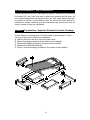
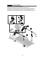
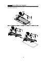
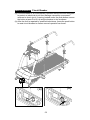
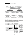
STEP 0 Preparation: Separate Product From the Package
Follow the A~E sequence and lay the main frame flat on the cardboard as
shown. Remove treadmill parts. Set them aside in a safe place. Cut the
corners of the box and flatten the cardboard.
A. Starting from the rear end, raise the main frame.
B. Remove packaging material at two sides of the treadmill.
C. Remove packaging material in the back of the treadmill.
D. Remove the right/left pedestals.
E. Finally, remove packaging material in the center of the treadmill.

12
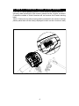
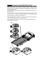
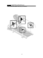
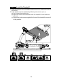
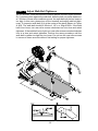
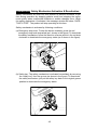
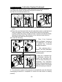
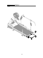
STEP 0 Preparation: Inspect Walk Belt Placement
Inspect the position of the walk belt in relation to the guide rollers. The walk
belt should be in the groove of the guide rollers (image ○). Make sure that
the walk belt is not outside of the groove of the guide rollers (image X), as
shown in illustration (A).
If the walk belt is in the wrong position, press the walk belt into the groove of
the guide rollers.
These guides should press the walk belt edges away from the deck, toward
the floor (image ○). Walk belt guides should not press the walk belt toward
the deck (image X), as shown in illustration (B).
If walk belt placement is incorrect, turn rear roller screws counterclockwise.
Then place the walk belt into the correct position.
After making sure the walk belt is in the correct position, adjust walk belt
tension as shown in step 9.
(B)
(A)

13
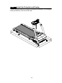
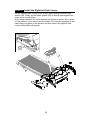
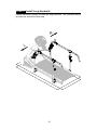
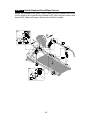
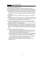
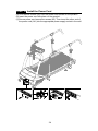
STEP 1 Install the Pedestals and Display
Follow instructions below to install the pedestals and display. The illustration
below provides an overview of this step.

14
STEP 1 Install the Pedestals and Display (Continued)
Remove screws (41) from the pedestal mount as shown.

15
(b)
(a)
(c)
(e)
(d)
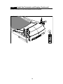
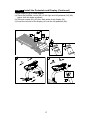
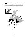
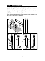
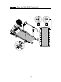
STEP 1 Install the Pedestals and Display (Continued)
Follow steps (a)~(e) in order to thread the data cable into the right pedestal.
(a) First, remove the zip tie on the cable in the right pedestal mount, and then
stretch the cable out as shown.
(Note: make sure the cable is fully pull out of the oval opening from the
pedestal mount.)
(b) Place the right pedestal (A2) on the floor, with the lower hole facing the
data cable. Disconnect the feeder cord (A3) from the bottom of the
pedestal. Wrap this feeder cord (A3) around the top of the data cable to
secure them together.
(c) Disconnect the feeder cord (A3) at the top of the right pedestal (A2).
(d) Pull the feeder cord (A3) to thread the data cable through the right
pedestal (A2).
(e) Once the data cable has been threaded through the pedestal, disconnect
the feeder cord (A3) from the data cable.

16
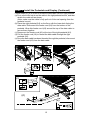
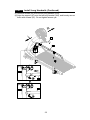
STEP 1 Install the Pedestals and Display (Continued)
Hold the data cables at the right and left pedestal (A2) (A8), and insert the
bottom of the right and left pedestal (A2) (A8) onto the pedestal mount.
Loosely secure them with screws (41). Do not tighten screws yet. Make sure
the right and left pedestal (A2) (A8) can still move slightly and then place the
water guards (A5) on the right and left pedestal (A2) (A8) higher than the
motor cover.
Note: Avoid pinching or crimping the data cable, and prevent it from falling
into the right pedestal.
Make sure the water guard with the correct side upward as shown
when placing on the pedestals.

17
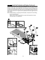
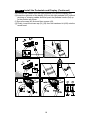
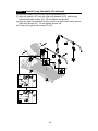
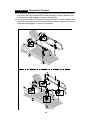
STEP 1 Install the Pedestals and Display (Continued)
Follow steps (a)~(g) to install display.
(a) Place the pedestal covers (A4) on the right and left pedestal (A2) (A8)
higher than the holes as shown.
(b) Remove screws (42) (43) from both sides of the display (A1).
(c) Insert the left side of the display (A1) into the left pedestal (A8).
R
L

18
STEP 1 Install the Pedestals and Display (Continued)
(d) Connect the cables from the right pedestal (A2) and the display (A1).
(e) Insert the right side of the display (A1) into the right pedestal (A2), without
pinching or crimping cables and then push the pedestal covers (A4) up
to the position as shown.
(f) Secure screws (42) first and then screws (43).
(g) Finally, insert the screw cap (31) (32) from the hardware kit (A10) onto the
screw head.
L
R
L
R
L
R

19
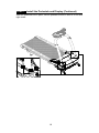
STEP 1 Install the Pedestals and Display (Continued)
After the pedestals are in place, secure pedestal screws in area A on left and
right sides.
A
La page est en cours de chargement...
La page est en cours de chargement...
La page est en cours de chargement...
La page est en cours de chargement...
La page est en cours de chargement...
La page est en cours de chargement...
La page est en cours de chargement...
La page est en cours de chargement...
La page est en cours de chargement...
La page est en cours de chargement...
La page est en cours de chargement...
La page est en cours de chargement...
La page est en cours de chargement...
La page est en cours de chargement...
La page est en cours de chargement...
La page est en cours de chargement...
La page est en cours de chargement...
La page est en cours de chargement...
La page est en cours de chargement...
La page est en cours de chargement...
La page est en cours de chargement...
La page est en cours de chargement...
La page est en cours de chargement...
La page est en cours de chargement...
La page est en cours de chargement...
La page est en cours de chargement...
La page est en cours de chargement...
La page est en cours de chargement...
La page est en cours de chargement...
La page est en cours de chargement...
La page est en cours de chargement...
La page est en cours de chargement...
La page est en cours de chargement...
La page est en cours de chargement...
La page est en cours de chargement...
La page est en cours de chargement...
La page est en cours de chargement...
La page est en cours de chargement...
La page est en cours de chargement...
La page est en cours de chargement...
La page est en cours de chargement...
La page est en cours de chargement...
La page est en cours de chargement...
La page est en cours de chargement...
La page est en cours de chargement...
La page est en cours de chargement...
La page est en cours de chargement...
La page est en cours de chargement...
La page est en cours de chargement...
La page est en cours de chargement...
-
 1
1
-
 2
2
-
 3
3
-
 4
4
-
 5
5
-
 6
6
-
 7
7
-
 8
8
-
 9
9
-
 10
10
-
 11
11
-
 12
12
-
 13
13
-
 14
14
-
 15
15
-
 16
16
-
 17
17
-
 18
18
-
 19
19
-
 20
20
-
 21
21
-
 22
22
-
 23
23
-
 24
24
-
 25
25
-
 26
26
-
 27
27
-
 28
28
-
 29
29
-
 30
30
-
 31
31
-
 32
32
-
 33
33
-
 34
34
-
 35
35
-
 36
36
-
 37
37
-
 38
38
-
 39
39
-
 40
40
-
 41
41
-
 42
42
-
 43
43
-
 44
44
-
 45
45
-
 46
46
-
 47
47
-
 48
48
-
 49
49
-
 50
50
-
 51
51
-
 52
52
-
 53
53
-
 54
54
-
 55
55
-
 56
56
-
 57
57
-
 58
58
-
 59
59
-
 60
60
-
 61
61
-
 62
62
-
 63
63
-
 64
64
-
 65
65
-
 66
66
-
 67
67
-
 68
68
-
 69
69
-
 70
70


SportsArt T655MD Le manuel du propriétaire
- Catégorie
- Tapis de course
- Taper
- Le manuel du propriétaire
dans d''autres langues
- English: SportsArt T655MD Owner's manual
Documents connexes
-
SportsArt T655MS Le manuel du propriétaire
-
-
-
-
-
-
-
-
-
Autres documents
-
Matrix TM543 Le manuel du propriétaire
-
Matrix Lifestyle Series Le manuel du propriétaire
-
-
 Fitnation CR2032 Manuel utilisateur
-
VIRTUFIT VFLOTR50i Manuel utilisateur
-
 Sunny Health & Fitness TM10 Under-Desk Remote-Controlled Le manuel du propriétaire
-
-
SUNNY Health Fitness RC2301 Manuel utilisateur
-
 Techness Run 100 Manuel utilisateur


