Furrion 50W Solar Panel Battery Maintainer Manuel utilisateur
- Catégorie
- Batteries rechargeables
- Taper
- Manuel utilisateur
Ce manuel convient également à

x 4
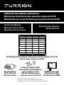
50W Solar Panel Battery Maintainer
Mainteneur de batterie pour panneau solaire de 50W
Mantenedor de carga de batería para panel solar de 50W
Instruction Manual
Manuel d’instructions
Manual de instrucciones
Model/Modèle/Modelo:
FSFP50MAT-BL
* Picture shown for reference only
Photo présentée à titre de référence seulement
La imagen que se muestra es únicamente de referencia
50W Rigid Solar Panel / Panneau solaire rigide de 50W
Panel solar rígido de 50W
Rooftop Box
Boîte de toit
Caja de techo
PWM Controller
Régulateur MLI
Controlador PWM
Z-Bracket Mount Kit
Ensemble d'installation
pour support en Z
Kit de montaje para
soporte en forma de Z
PWM SOLAR CHARGE
CONTROLLER GEN 2.0
Model: C-FSFP50MAT-A03
System Voltage: 12V
Mode Key
CAUTION: The default setting is for use with
sealed lead-acid batteries. For a dierent
battery type, please refer to the instruction
manual or visit www.furrion.com.

1
Thank you for purchasing this Furrion® product. Before operating or installing, please read these
instructions carefully. This instruction manual contains information for safe use, installation, and
maintenance of the product.
Please keep this instruction manual in a safe place for future reference. Be sure to pass on this
manual to new owners of this product.
The manufacturer does not accept responsibility for any damages due to not observing these
instructions.
Supplier’s Declaration of Conformity
47 CFR § 2.1077 Compliance Information
Unique Identifier:
Trade Name: Furrion
Model Number: C-FSFP50MAT-A03
Responsible Part--U.S. Contact Information
Furrion Innovation Center & Institute of Technology
52567 Independence Ct., Elkhart, IN 46514, USA
Toll free:1-888-354-5792;
Email: [email protected]
FCC Compliance Statement(for products subject to Part 15):
This device complies with Part 15 of the FCC Rules. Operation is subject to the
following two conditions: (1) This device may not cause harmful interference, and (2)
this device must accept any interference received, including interference that may
cause undesired operation.
English

2
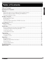
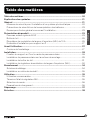
Table of Contents ....................................................................................................... 2
Explanation of Symbols ............................................................................................ 3
General ........................................................................................................................ 3
Safety Precautions for Installing a Photovoltaic System ....................................................4
Safety Precautions When Working with Batteries ................................................................4
General Installation Notes ................................................................................................................ 5
Product Overview ...................................................................................................... 5
50W Rigid Solar Panel ........................................................................................................................5
Rooftop Box ............................................................................................................................................ 6
10A Pulse Width Modulation (PWM) Controller ......................................................................7
Z-Bracket Mount Kit ............................................................................................................................ 8
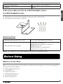
Before Using ............................................................................................................... 8
What’s in the Box ..................................................................................................................................8
Installation .................................................................................................................. 9
Secure Z-Brackets to Frame of the Solar Panel .....................................................................9
Install Solar Panel to Mounting Surface .....................................................................................10
Install Rooftop Box ...............................................................................................................................12
Install PWM Controller .......................................................................................................................13
Connection .................................................................................................................. 15
Wiring Diagram ......................................................................................................................................15
Installation on RV ..................................................................................................................................15
Operation..................................................................................................................... 16
Suggested Use ......................................................................................................................................16
PWM Controller Status Indicators ................................................................................................ 16
Mode Selection .....................................................................................................................................16
Charging Parameters..........................................................................................................................17
Troubleshooting ......................................................................................................... 17
Maintenance ............................................................................................................... 18
Table of Contents
English

3
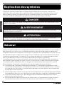
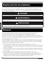
Explanation of Symbols
This manual has safety information and instructions to help eliminate or reduce the risk of
accidents and injuries. Always respect the safety warnings identified by the following symbols.
The following safety phrases indicate the degree of risk of injury or property damage.
DANGER
Indicates an imminently hazardous situation which, if not avoided, will result in death or
serious injury.
WARNING
Indicates a potentially hazardous situation which, if not avoided, could result in death or
serious injury.
CAUTION
Indicates a potentially hazardous situation which, if not avoided, may result in minor or
moderate personal injury, or property damage.
General
Please carefully read the following installation and safety instructions. Non-compliance with
these instructions may void the product warranty.
This guide contains information regarding the installation and safe handling of Furrion solar panels
and components. All instructions must be read and understood before attempting installation. If
there are any questions, please contact your dealer or Furrion for further information.
The installer should conform to all safety precautions in the guide when installing solar panels.
Before installing a solar photovoltaic system, the installer should become familiar with the
mechanical and electrical requirements for photovoltaic systems. Keep this guide in a safe place
for future reference.
● The installation of solar photovoltaic (PV) systems requires specialized skills and knowledge.
The installer assumes all risk of injury, including risk of electric shock. Solar panels
installation should be performed only by qualified persons.
● All solar panels come with a permanently attached junction box. Your dealer can provide
additional extension cables to simplify module wiring.
● Exercise caution when wiring or handling solar panels exposed to sunlight.
● Do not connect or disconnect wires attached to solar panels when they are exposed to
sunlight, otherwise an electric arc may occur. Arcs can cause burns, fires, or other safety
problems. Always exercise caution when connecting and disconnecting wiring solar panels.
● Photovoltaic solar modules convert light energy to direct-current electrical energy and are
designed for outdoor use. Proper design of support structures is the responsibility of the
system designer and installer.
English

4
● Do not attempt to disassemble the solar panel, and do not remove any attached nameplates
or components. Doing so will void the warranty.
● Do not apply paint or adhesive to the solar panel.
● Do not use mirrors or other hardware to artificially concentrate sunlight on the solar panel.
● When installing solar panels, observe all applicable local, regional, and national codes &
regulations. Obtain a building and/or electrical permit when required.
Work Safely
● Wear protective eye wear and appropriate clothing during installation. Use extreme caution
when working with electricity and when working around batteries. Use properly insulated
tools only.
● Use care when working on an RV roof, always use rated safety harnesses and ladders during
installation and maintenance.
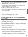
Safety Precautions for Installing a Photovoltaic System
● Solar panels produce electrical energy when exposed to sunlight.
● Keep children well away from the system while transporting and installing mechanical and
electrical components.
● Completely cover all solar panels with an opaque material during installation to prevent
electricity from being generated.
● Do not wear metallic rings, watches, or other metallic devices while installing or
troubleshooting photovoltaic systems.
● Use appropriate safety equipment (insulated tools, insulating gloves, etc.) approved for use
on electrical installations.
● Observe the instructions and safety precautions for all other components used in the system,
including wiring and cables, connectors, DC-breakers, mounting hardware, inverters, etc.
● Use only equipment, connectors, wiring, and mounting hardware suitable for use in a
photovoltaic system.
● Always use the same type of solar panel within a particular photovoltaic system.
● Under normal operating conditions, solar panels will produce currents and voltages that may
vary with than those listed in the data sheet. Data sheet values are applicable at standard
test conditions only.
● Short-circuit current and open-circuit voltages should be multiplied by a factor of 1.25 when
determining the system voltage/ampacity rating for the fuses and charge controllers.
Safety Precautions When Working with Batteries
● Batteries contain very corrosive diluted sulfuric acid as electrolyte. Precautions should be
taken to prevent contact with skin, eyes, or clothing.
● Batteries generate hydrogen and oxygen during charging, which may form an explosive gas
mixture.
● Store batteries in a well ventilated area and follow the battery manufacturer’s
recommendations. Never smoke, allow a spark, or flame near the batteries.
● Never allow a foreign object to drop or rest on the battery. Doing so could lead to fire,
explosion, or harmful out-gassing.
English

5
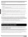
● Remove metal items such as rings, bracelets, and watches when working with batteries. The
batteries can produce a short circuit current high enough to weld a ring or similar object to
the metal, causing a severe burn.
● If you need to remove a battery, always remove the negative terminal from the battery first.
● Only use properly insulated tools when making battery connections.
General Installation Notes
● Drainage holes must not be covered by the mounting system. The solar panel should be
mounted with glass surface upwards.
● Do not lift the solar panel by grasping its junction box or electrical leads.
● Do not stand or step on the solar panel.
● Do not drop the solar panel or allow objects to fall on the solar panel.
● Do not place any heavy objects on the solar panel.
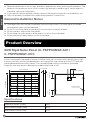
Product Overview
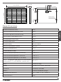
50W Rigid Solar Panel (C- FSFP50MAT-A01 /
C- FSFP50MAT-001)
Furrion solar panels are made of monocrystalline solar cells in series with high efficiency, high
transmission rate, low iron tempered glass, anti-aging EVA, high flame resistant TPT laminate,
and anodized aluminium alloy frames. They are designed for easy installation, extended
longevity, and resistance to damage incurred by high wind or hail.
26⁄” (670mm)
1⁄” (30mm)
4⁄”
(123mm)
4⁄”
(123mm)
35⁄” (900mm)
4*⁄” (6mm)
21⁄” (540mm)
Specifications
Maximum Power (Pmax) 50W
Max Power Voltage (Vmp) 18.5V
Max Power Current (Imp) 2.7A
English

6
Open Circuit Voltage (Voc) 22.6V
Short Circuit Current 2.9A
Cell Efficiency 18%
Cell Type Monocrystalline
Maximum System Voltage 36V DC
Power Tolerance ± 5%
Series Fuse Rating 5A
Temperature Co-efficient (Power) -0.43%/ °C
Temperature Co-efficient (Voltage) -0.32%/°C
Temperature Co-efficient (Current) +0.02%/ °C
NOCT (Air 20°C, Sun 0.8kW/m², Wind 1m/s) 45±3°C
Weight 9.26lbs (4.2kg)
Cable 2.5mm
2
, PV1-F, 35⅜”(900mm)
Connector Stranded Lead
Frame Anodized Aluminum (Black)
Operation Temperature -40°F to 185°F (-40°C to 85°C)
IP Rating IP65
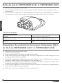
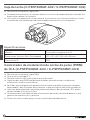
Rooftop Box (C-FSFP50MAT-A02 / C-FSFP50MAT-002)
● IP65 dust and water resistant.
● Designed to mount with adhesive sealant or standard #8 RV button head screws (not
included).
● Constructed with anti-UV agent to extend weather resistance and to limit color change
during long periods of exposure to the elements.
Specifications
Material Constructed with anti-UV agent
Dimension (W x H x D) 5⅛” x 1¾” x 3⅝” (130 x 43 x 93 mm)
IP Rating IP65
English

7
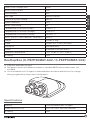
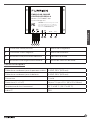
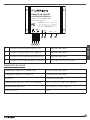
10A Pulse Width Modulation (PWM) Controller
(C-FSFP50MAT-A03 / C-FSFP50MAT-003)
● IP65 dust and water resistant.
● 12V system voltage.
● LED numeric display and mode selection button.
● Intelligent 3-stage PWM charging algorithm applies variable equalization, boost, and float
modes.
● Smart charging profile ensures that batteries are fully charged, balanced, and desulfurized
effectively extending the service life of the batteries.
● Charging program options are available for sealed, GEL, flooded lead acid, or lithium iron
phosphate batteries.
● Controller memory retains mode and battery type information, making operation easy and
convenient.
● Protection against overcharge and reverse polarity connection.
1 2 3 4
5 6 7 8
PWM SOLAR CHARGE
CONTROLLER GEN 2.0
Model: C-FSFP50MAT-A03
System Voltage: 12V
Mode Key
CAUTION: The default setting is for use with
sealed lead-acid batteries. For a dierent
battery type, please refer to the instruction
manual or visit www.furrion.com.
1 Positive solar input lead 5 Charge indicator
2 Negative solar input lead 6 Battery indicator
3 Positive battery output lead 7 Mode indicator
4 Negative battery output lead 8 Mode selection button
Specifications
Cable for Solar Panel Connection 14AWG, 23⅝" (600mm)
Cable for Battery Connection 14AWG, 23⅝" (600mm)
Connector Stranded Lead
Dimension (W x H x D) 3¼" x ⁄” x 2⁄” (82 x 20 x 58 mm)
English

8
Operation Temperature -31°F to 149°F (-35°C to 65°C)
IP Rating IP65
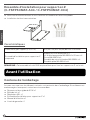
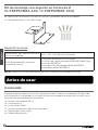
Z-Bracket Mount Kit (C-FSFP50MAT-A04 /
C-FSFP50MAT-004)
● Aluminum construction with stainless steel nuts, bolts, and washers.
● Maintenance free & easy installation.
x 4
Specifications
Dimension (per bracket) (W x H x D) 3⁄" x 1⅝" x 3⅞" (88 x 42 x 100 mm)
Z-Bracket Mount Kit includes
Aluminum Z-Bracket x4
M6 SS304 Hex Head Bolt x 20mm x4
M6 SS304 Nut x4
M6 SS304 Split Lock Washer x4
M6 SS304 Flat Washer x8
NOTE: This kit does NOT include hardware to attach the Z-Brackets to roof.
Before Using
What’s in the Box
Make sure you have all the following items included in the packaging. If any item is damaged or
missing, contact your dealer.
● 50W Rigid Solar Panel x 1
● Rooftop Box x 1
● PWM Controller x 1
● Z-Bracket Mount Kit x 1
● Quick Start Guide x 1
● Warranty Manual x 1
English

9
Installation
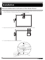
Secure Z-Brackets to Frame of the Solar Panel
1. Affix a Z-Bracket along the short side of the solar panel frame. Make sure that mounting foot
of the Z-Bracket is facing outward from the solar panel frame.
+
-
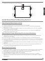
2. Align the mounting hole of the Z-Bracket with that of the solar panel frame.
+
-
3. Fix the Z-Bracket on the solar panel frame.
M6 Nut
M6 Hex Bolt
M6 Split Lock
Washer
M6 Flat Washer
M6 Flat Washer
English

10
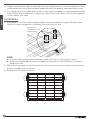
4. Repeat the steps above for each Z-Bracket.
+
-
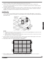
Install Solar Panel to Mounting Surface
Selecting the Mounting Location
● Select a suitable location for the installation of the solar panel.
● Install the solar panel in a clear location on the roof of the RV that will receive maximum
exposure to the sun.
● Solar panels should be mounted as far away from rooftop obstructions (AC units, plumbing
vents, skylights, etc.) as possible.
● If solar panels must be installed near rooftop obstructions, try to orient the modules with
broadside facing the obstruction.
Selecting the Proper Mounting Structure and Hardware
● Observe all instructions and safety precautions included with the mounting system to be
used with the solar panel.
● Do not drill holes in the glass surface of the solar panel. Doing so will void the warranty.
● Do not drill additional mounting holes in the solar panel frame. Doing so will void the warranty.
● Solar panels must be securely attached to the mounting structure using four mounting points
for normal installation.
● The mounting structure and hardware must be made of durable, corrosion, and UV-resistant
materials.
● Select mounting location such that screw holes on the mounting brackets attached to the
solar panel frame are aligned with the structural framing of the roof.
Mounting Solar Panels
● In regions with heavy snowfall in winter, select the height of the mounting system so that the
lowest edge of the solar panel is not covered by snow for any extended period of time.
● Solar panels must be securely attached to the mounting structure.
● Provide adequate ventilation under the solar panel.
● Before installing solar panels on a roof, ensure that the roof construction is suitable. In
addition, any roof penetration required to mount the solar panel must be properly sealed to
prevent leaks.
English

11
● Always keep the backsheet of the panel free from foreign objects or structural elements, which
could come into contact with the panel, especially when the panel is under mechanical load.
● Ensure panels are not subjected to wind or snow loads exceeding the maximum permissible
loads (176lbs/80kg), and are not subjected to excessive forces due to the thermal expansion
of the support structures.
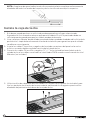
Installation
1. Affix panels to roof by screwing appropriate mounting hardware through Z-Bracket holes
into roof. Install solar panel on a relatively flat surface on the roof.
(fasteners not
included, #10 screws
recommended)
NOTE:
● Ensure screw locations are backed by a solid structure such as a rafter, stud, etc.
● Apply self-leveling adhesive (not included) to the bottom of the Z-Brackets to create a
water tight seal.
2. Mount the solar panel such that at least 2 of the mounting feet have screws penetrating the
metal or wooden framing trusses.
3. Repeat for all fastener locations.
English

12
4. Seal around edges of all Z-Brackets and screws where they come in contact with or
penetrate the mounting surface.
NOTE: Make sure that self-leveling silicon adhesive is applied evenly around all edges of
bracket and the mounting screws with no gaps.
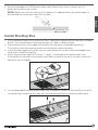
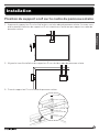
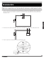
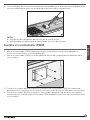
Install Rooftop Box
1. Drill a small pilot hole on the chosen location, if desired. Enlarge the pilot hole with a suitable
drill bit. The hole drilled must be large enough for cables to drop through.
2. File and remove any sharp edges around the hole that were created during drilling.
Thoroughly clean the mounting area to ensure proper sealant bonding.
3. Insert positive/negative PV wires from the solar panel junction box into the threaded strain
relief holes on the Rooftop Box.
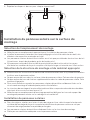
4. Attach the positive/negative PV wires ("+" and "-" on the tape at the end) inside of the
Rooftop Box to the wires connected to the PWM controller using twist-on wire connectors/
Marrettes (not included).
5. Use standard #8 RV button head screws (not included) to fasten the Rooftop Box to the RV
roof by drilling through the 3 screw holes around the perimeter of the Rooftop Box base.
English

13
6. Use appropriate self-leveling silicon sealant as recommended by your RV dealer or
manufacturer to properly seal the perimeter of the Rooftop Box.
NOTE:
● Tighten the strain reliefs on the Rooftop Box.
● Apply self-leveling adhesive (not included) to the mounting hole.
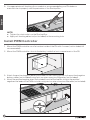
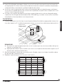
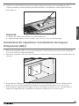
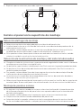
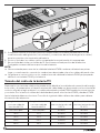
Install PWM Controller
1. Mount the PWM controller on a flat surface inside of the RV with 4 screws (not included, #3
recommended).
2. Mount the PWM controller close to the battery inside the front compartment of the RV.
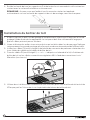
3. Attach the positive/negative battery wire leads on the PWM controller to the positive/negative
battery cables (not included) using twist-on wire connectors/Marrettes (not included).
4. Attach the positive/negative wires (not included) from the Rooftop Box to the to the positive/
negative solar leads on the PWM controller using twist-on wire connectors/Marrettes (not included).
English

14
5. Ensure that an appropriate electrical connection is made with the battery by using twist-
on wire connectors/Marrettes (not included), and crimping ring connectors (or similar) for
connection to battery terminals.
6. Fasten and secure all loose wires according to the appropriate electrical code.
7. A 10A in-line fuse is recommend to be installed on the positive battery side within 7 inches of
the positive battery post.
NOTE:
● It is recommended to connect the PWM battery output leads to the battery first, then
connect the solar input leads to the solar panel wires.
● Do not short circuit the PWM battery output leads, doing so may damage the PWM controller
and/or battery.
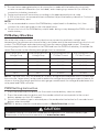
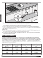
PV/Battery Wire Size
Since the solar output current can vary due to array connection methods, sunlight, and
temperature, the minimum wire size must be in accordance with the maximum array short-circuit
current. The PWM input and output wires will have the same voltage and current. Therefore,
the wire gauge from the solar panel to the PWM and from the PWM to the battery should be the
same. Please refer to the following wire gauge chart for reference:
Wire Length with 10%
Voltage Drop
Wire Length with 3%
Voltage Drop
Wire Gauge with 5A
PV Max Current
Wire Gauge with 10A
PV Max Current
0 to 20 ft 0 to 6 ft 16 AWG 16 AWG
30 ft 10 ft 16 AWG 14 AWG
50 ft 15 ft 16 AWG 12 AWG
65 ft 20 ft 14 AWG 10 AWG
80 ft 25 ft 12 AWG 10 AWG
NOTE: The wire size is only for reference. If there is a long distance between the PV system and
the controller, larger wires can be used to reduce the voltage drop and improve performance. As
shown a shorter wire length and thicker wire gauge can decrease the voltage drop between the
solar panel and PWM controller.
PWM Setting Instruction
1. Press the mode selection button for 3 seconds to enter battery selection mode.
2. Press the mode selection button until the number value that corresponds to the correct
battery appears on the LED readout.
3. Once correct battery type is selected, press the mode selection button for 3 seconds to exit
battery selection mode.
NOTE: For battery selection mode please refer to Mode Selection section.
CAUTION
The default setting is for use with sealed lead-acid batteries. For a different battery type,
please refer to the instruction manual or visit www.furrion.com.
English

15
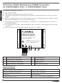
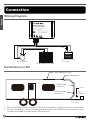
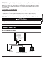
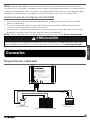
Connection
Wiring Diagram
12V
Battery
+
-
Rooftop box
50W Rigid Solar Panel
(Fuse and 12V battery
not included.)
Fuse
PWM SOLAR CHARGE
CONTROLLER GEN 2.0
Model: C-FSFP50MAT-A03
System Voltage: 12V
Mode Key
CAUTION: The default setting is for use with
sealed lead-acid batteries. For a dierent
battery type, please refer to the instruction
manual or visit www.furrion.com.
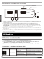
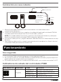
Installation on RV
50W Rigid Solar Panel
Rooftop Box
12V
Battery
16AWG Cable
(Inside RV)
PWM Controller
(Inside RV)
Fuse
(Fuse and 12V battery
not included.)
1. Mount the PWM controller inside of the RV near the battery inside of the front compartment.
2. Connect the battery's positive and negative terminals to the PWM controller battery output
(installer may need to create an exit hole and seal).
English

16
NOTE: Installer will need to provide battery terminal connections and wire to make
connection between PWM controller and battery or batteries.
3. Plug the positive and negative leads from the PV extension cable directly into the Rooftop Box.
4. Identify the positive and negative cables terminated from the Rooftop Box and route them to
the PWM controller for the final connections.
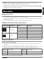
Operation
Suggested Use
1. The PWM controller is intended for a 12 volt battery system.
2. It is advised to install PWM controller in a well ventilated environment as device may become
warm during operation.
3. Choose battery cables with minimum 16AWG gauge rated for 10A DC.
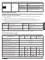
PWM Controller Status Indicators
LED indicators Indications Status Funcitons
Charging
Solid on Solar panel has voltage
Solid off Solar panel has no voltage
Slow flashing Charging in process
Quick flashing System over voltage
Battery
Solid on Normal battery function
Solid off Battery is not connected
Slow flashing Battery is under voltage
Quick flashing Battery is over discharged
Mode Selection
Battery Type Selection Method:
● Press the button for 3 seconds. The LED will begin to flash indicating that the mode can be
changed.
● When the button is pressed again the LED number display will change from (1-4).
● When the number value corresponds to the battery type selected by the user, wait until the
LED stops flashing or press the button again for 3 seconds to complete the setting.
Numeric
Indicator
Battery Type
Numeric
Indicator
Battery Type
1 Sealed lead-acid batteries 3 Flooded lead-acid batteries
2 GEL lead-acid batteries 4 Lithium iron phosphate batteries
NOTE: Default setting: Sealed lead-acid batteries.
English

17
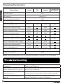
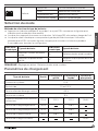
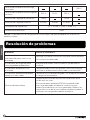
Charging Parameters
Battery Type Sealed GEL Flooded
Lithium iron
phosphate
System current 10A
No-load loss 10mA/12V
Solar energy input voltage <55V
System voltage 12V
Overvoltage protection 17.0V 17.0V 17.0V 16.6V
Equalizing charging voltage 14.6V 14.8V
Boost charging voltage 14.4V 14.2V 14.6V
Floating charging voltage 13.8V 13.8V 13.8V
Constant charge voltage 14.6V
Constant charge recovery voltage 13.6V
Boost charging recovery voltage 13.2V 13.2V 13.2V
Equalizing charging duration 1 hour 1 hour
Boost charging duration 4 hours 4 hours 4 hours
Operation temperature -31
o
F to 149
o
F (-35
o
C to 65
o
C)
Protection degree IP65
NOTE: Charging parameters may vary based on availability of sunlight on the solar panels.
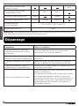
Troubleshooting
Symptoms Causes and Solutions
While sunlight is present, the solar
panel indicator does not light up.
Check whether the solar panel is correctly connected
and contact is adequate.
The solar panel charging indicator
is flashing quickly.
Ensure that the correct battery type has been selected.
The battery indicator does not
light up.
The battery may be failing to supply power. Check
whether the battery is correctly connected.
English

18
The battery indicator is flashing
quickly, and there is no output.
The battery is over-discharged and will recover when
recharged adequately.
Battery voltage is low.
Reposition vehicle if possible to provide more direct
sunlight. If PWM Battery Maintainer can not sustain
adequate charge to the battery, connect the coach to shore
power or generator. Reducing electrical loads in the coach
will also help maintain adequate charge of the battery.
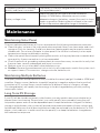
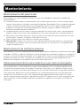
Maintenance
Maintaining Solar Panel
To ensure optimum performance, Furrion recommends the following maintenance measures:
● Clean the glass surface of the solar panel when required. Always use clean water and a soft
sponge or cloth for cleaning. A mild, non-abrasive cleaning agent may be used to remove
stubborn dirt. Do not use cold water to clean panel if the surface is extremity hot as rapid
temperature change could lead to cracking.
● Clean solar panel more frequently during drier months, as they may become covered in dust
more quickly. A pressure washer is not recommended.
● Check the electrical, grounding, and mechanical connections every six months to verify that
they are clean, secure, undamaged, and free of corrosion.
● Remove snow, ice, or other debris when build up occurs.
● Caution: Observe the maintenance instructions for all components used in the system, such
as support frames, PV connectors, charge controller, batteries, etc.
Maintaining Multiple Batteries
To properly maintain multiple batteries they should be the same type (gel, flooded or AGM) and
condition. Always connect batteries in parallel (negative to negative and positive to positive)
to maintain a 12V system. Never connect batteries at different states of charge or voltage.
The charged battery will rapidly transfer energy to the discharged battery possibly causing
catastrophic failure.
Long Term RV Storage
If your RV will be stored in extremely cold climates you may need to remove your batteries to
prevent them from freezing. Please note if your solar panel(s) are covered by snow they will
not produce power and can not be depended upon to keep the batteries charged. For battery
storage in mild climates solar system will provide more power provided sufficient sunlight and
limited load. Make sure that all passive/phantom loads are removed from the batteries, i.e. DVD
players, clock radio, etc. to make sure the solar panel(s) can keep the batteries charged even
with reduced sun exposure.
English

19
Merci d’avoir acheté ce produit Furrion®. Avant d’utiliser ou d’installer votre nouveau produit,
veuillez lire attentivement les présentes instructions. Le présent manuel d’instructions contient des
informations permettant une utilisation, une installation et un entretien en toute sécurité du produit.
Veuillez conserver le présent manuel d’instructions en lieu sûr afin de pouvoir vous y référer
ultérieurement. Veillez à transmettre le présent manuel à tout nouveau propriétaire de ce produit.
Le fabricant décline toute responsabilité pour tous dommages résultant du non-respect des
présentes consignes.
Déclaration de conformité du fournisseur
47 CFR § 2.1077 Informations de conformité
Identificateur unique
Nom commercial : Furrion
N° de modèle : C-FSFP50MAT-A03
Partie responsable – Coordonnées de la personne-ressource aux
États-Unis
Furrion Innovation Center & Institute of Technology 52567 Independence Ct,
Elkhart, IN 46514, USA
États-Unis Numéro de téléphone gratuit : 1-888-354-5792;
Courriel : [email protected]
Déclaration de conformité FCC
Cet appareil est conforme à l'article 15 du Règlement de la FCC. Son utilisation
est assujettie aux deux conditions suivantes : (1) Cet appareil ne doit pas causer
d'interférences nuisibles, et (2) cet appareil doit accepter toute autre interférence
reçue, y compris les interférences pouvant entraîner un fonctionnement non désiré.
Français
La page est en cours de chargement...
La page est en cours de chargement...
La page est en cours de chargement...
La page est en cours de chargement...
La page est en cours de chargement...
La page est en cours de chargement...
La page est en cours de chargement...
La page est en cours de chargement...
La page est en cours de chargement...
La page est en cours de chargement...
La page est en cours de chargement...
La page est en cours de chargement...
La page est en cours de chargement...
La page est en cours de chargement...
La page est en cours de chargement...
La page est en cours de chargement...
La page est en cours de chargement...
La page est en cours de chargement...
La page est en cours de chargement...
La page est en cours de chargement...
La page est en cours de chargement...
La page est en cours de chargement...
La page est en cours de chargement...
La page est en cours de chargement...
La page est en cours de chargement...
La page est en cours de chargement...
La page est en cours de chargement...
La page est en cours de chargement...
La page est en cours de chargement...
La page est en cours de chargement...
La page est en cours de chargement...
La page est en cours de chargement...
La page est en cours de chargement...
La page est en cours de chargement...
La page est en cours de chargement...
La page est en cours de chargement...
La page est en cours de chargement...
La page est en cours de chargement...
La page est en cours de chargement...
La page est en cours de chargement...
-
 1
1
-
 2
2
-
 3
3
-
 4
4
-
 5
5
-
 6
6
-
 7
7
-
 8
8
-
 9
9
-
 10
10
-
 11
11
-
 12
12
-
 13
13
-
 14
14
-
 15
15
-
 16
16
-
 17
17
-
 18
18
-
 19
19
-
 20
20
-
 21
21
-
 22
22
-
 23
23
-
 24
24
-
 25
25
-
 26
26
-
 27
27
-
 28
28
-
 29
29
-
 30
30
-
 31
31
-
 32
32
-
 33
33
-
 34
34
-
 35
35
-
 36
36
-
 37
37
-
 38
38
-
 39
39
-
 40
40
-
 41
41
-
 42
42
-
 43
43
-
 44
44
-
 45
45
-
 46
46
-
 47
47
-
 48
48
-
 49
49
-
 50
50
-
 51
51
-
 52
52
-
 53
53
-
 54
54
-
 55
55
-
 56
56
-
 57
57
-
 58
58
-
 59
59
-
 60
60


Furrion 50W Solar Panel Battery Maintainer Manuel utilisateur
- Catégorie
- Batteries rechargeables
- Taper
- Manuel utilisateur
- Ce manuel convient également à
dans d''autres langues
Documents connexes
-
Furrion Aurora 43 Inch Full Shade Smart 4K UHD LED Outdoor TV Manuel utilisateur
-
Furrion FSPK10MWT-BL Manuel utilisateur
-
Furrion FBN12C33A1 Mode d'emploi
-
Furrion FCN48TASF Manuel utilisateur
-
Furrion Aurora Shade Manuel utilisateur
-
-
Furrion F2GWH Manuel utilisateur
Autres documents
-
STRUCTUBE WAWA Assembly Instructions
-
GYS Anti-arc protection 12 V Fiche technique
-
Sunforce 30 Amp, 12-Volt Solar Charge Controller Manuel utilisateur
-
-
Dometic Büttner MT90, MT180-2, MT130, MT260-2, MT210, MT420-2, MT130CDS, MT260-2CDS, MT210CDS, MT420-2CDS Mode d'emploi
-
 Go Power! Overlander Manuel utilisateur
-
-
Morningstar Tristar Manuel utilisateur
-
Samlexpower SCC-30AB Le manuel du propriétaire
-
Victron energy BlueSolar MPPT Charge Controller 12V 24V 40A Le manuel du propriétaire
