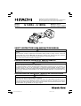
Hitachi G 18DSL Safety Instructions And Instruction Manual
- Catégorie
- Outils électroportatifs
- Taper
- Safety Instructions And Instruction Manual
Ce manuel convient également à

INSTRUCTIONS DE SECURITE ET MODE D’EMPLOI
AVERTISSEMENT
Une utilisation INCORRECTE OU DANGEREUSE de cet outil motorisé peut entraîner la
mort ou de sérieuses blessures corporelles!
Ce mode d’emploi contient d’importantes informations à propos de la sécurité de ce
produit. Prière de lire et de comprendre ce mode d’emploi AVANT d’utiliser l’outil
motorisé. Garder ce mode d’emploi à la disponibilité des autres utilisateurs et propriétaires
avant qu’ils utilisent l’outil motorisé. Ce mode d’emploi doit être conservé dans un
endroit sûr.
INSTRUCCIONES DE SEGURIDAD Y MANUAL DE INSTRUCCIONES
ADVERTENCIA
¡La utilización INAPROPIADA O PELIGROSA de esta herramienta eléctrica puede
resultar en lesiones de gravedad o la muerte!
Este manual contiene información importante sobre la seguridad del producto. Lea y
comprenda este manual ANTES de utilizar la herramienta eléctrica. Guarde este manual
para que puedan leerlo otras personas antes de utilizar la herramienta eléctrica. Este
manual debe ser guardado en un lugar seguro.
SAFETY INSTRUCTIONS AND INSTRUCTION MANUAL
WARNING
IMPROPER OR UNSAFE use of this power tool can result in death or serious bodily
injury!
This manual contains important information about product safety. Please read and
understand this manual BEFORE operating the power tool. Please keep this manual
available for other users and owners before they use the power tool.
This manual should be stored in safe place.
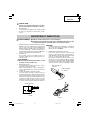
Model Cordless Disc Grinder
Modèle Meuleuse sans fil
Modelo Amoladora angular a bateríe
G 14DSL
•
G 18DSL
G14DSL
Designed for operating in USA & Canada only.
When this product is used in areas other than the USA & Canada,
we cannot guarantee the product quality and performance.
00Cover_G14DSL_US 9/4/13, 15:121

CONTENTS
Page
IMPORTANT SAFETY INSTRUCTIONS ............... 3
MEANINGS OF SIGNAL WORDS ........................ 3
SAFETY ...................................................................... 3
GENERAL POWER TOOL SAFETY WARNINGS.. 3
SAFETY WARNINGS FOR GRINDING OPERATIONS ..
5
KICKBACK AND RELATED WARNINGS .............. 6
SAFETY WARNINGS SPECIFIC FOR
GRINDING OPERATIONS .............................. 6
GENERAL SAFETY INSTRUCTIONS FOR GRINDERS .......
6
SPECIFIC SAFETY RULES AND SYMBOLS ......... 7
IMPORTANT SAFETY INSTRUCTIONS FOR
BATTERY CHARGER ...................................... 8
IMPORTANT SAFETY INSTRUCTIONS FOR
USE OF THE BATTERY AND BATTERY CHARGER .......
9
CAUTION ON LITHIUM-ION BATTERY ............... 9
Page
FUNCTIONAL DESCRIPTION .................................. 11
NAME OF PARTS ................................................ 11
SPECIFICATIONS ................................................ 12
ASSEMBLY AND OPERATION ............................... 13
APPLICATIONS ................................................... 13
REMOVAL AND INSTALLATION METHOD OF
BATTERY ...................................................... 13
CHARGING METHOD ......................................... 13
PRIOR TO OPERATION ....................................... 15
GRINDER OPERATION ....................................... 16
DEPRESSED CENTER WHEEL
ASSEMBLY AND DISASSEMBLY ............... 17
MAINTENANCE AND INSPECTION ....................... 18
ACCESSORIES ......................................................... 20
STANDARD ACCESSORIES ............................... 20
PARTS LIST .............................................................. 59
English
ÍNDICE
Español
Página
INSTRUCCIONES IMPORTANTES SOBRE SEGURIDAD ...
40
SIGNIFICADO DE LAS PALABRAS DE SEÑALIZACIÓN ...
40
SEGURIDAD ............................................................. 40
ADVERTENCIAS DE SEGURIDAD GENERAL DE
LA HERRAMIENTA ELÉCTRICA .................. 40
ADVERTENCIAS DE SEGURIDAD PARA MOLER ......
42
REBOTE Y ADVERTENCIAS RELACIONADAS
...... 43
ADVERTENCIAS DE SEGURIDAD PARA MOLER
..... 43
INSTRUCCIONES GENERALES DE SEGURIDAD
PARA AMOLADORAS ................................. 44
NORMAS Y SÍMBOLOS ESPECÍFICOS DE
SEGURIDAD ................................................. 44
INSTRUCCIONES IMPORTANTES DE
SEGURIDAD PARA EL CARGADOR DE
BATERÍAS ..................................................... 46
INSTRUCCIONES IMPORTANTES DE
SEGURIDAD PARA LA BATERÍA Y EL
CARGADOR DE BATERÍAS ......................... 46
Página
ADVERTENCIA DE LA BATERÍA DE LITIO ......... 47
DESCRIPCIÓN FUNCIONAL .................................... 49
NOMENCLATURA ............................................... 49
ESPECIFICACIONES ............................................ 50
MONTAJE Y OPERACIÓN ...................................... 51
APLICACIONES ................................................... 51
MÉTODO DE EXTRACCIÓN E INSTALACIÓN
DE LA BATERÍA ............................................ 51
MÉTODO DE CARGA .......................................... 51
ANTES DE LA OPERACIÓN ................................ 53
OPERACIÓN DE LA AMOLADORA
ANGULAR .................................................... 54
MONTAJE Y DESMONTAJE DE LA
RUEDA DE DISCO ABOMBADO ................. 55
MANTENIMIENTO E INSPECCIÓN ........................ 56
ACCESORIOS ........................................................... 58
ACCESORIOS ESTÁNDAR ................................. 58
LISTA DE PIEZAS .................................................... 59
Page
CONSIGNES DE SÉCURITÉ IMPORTANTES..... 21
SIGNIFICATION DES MOTS D’AVERTISSEMENT .....
21
SECURITE ................................................................ 21
AVERTISSEMENTS DE SÉCURITÉ GÉNÉRAUX
CONCERNANT LES OUTILS ÉLECTRIQUES...
21
AVERTISSEMENTS DE SÉCURITÉ POUR LES
OPÉRATIONS DE MEULAGE ...................... 23
RECUL DE L'APPAREIL ET AVERTISSEMENTS
ASSOCIÉS .................................................... 24
AVERTISSEMENTS DE SÉCURITÉ SPÉCIFIQUES
AUX OPÉRATIONS DE MEULAGE ............... 24
CONSIGNES DE SECURITE GENERALES
RELATIVES AUX MEULEUSES DROITES ....
25
REGLES DE SECURITE SPECIFIQUES ET SYMBOLES ....
25
CONSIGNES DE SÉCURITÉ IMPORTANTES
POUR LE CHARGEUR DE BATTERIE .......... 27
CONSIGNES DE SÉCURITÉ IMPORTANTES
POUR L’UTILISATION DE LA BATTERIE ET
DU CHARGEUR DE BATTERIE .................... 27
Français
Page
PRÉCAUTIONS RELATIVES A LA BATTERIE AU
LITHIUM ION ................................................ 28
DESCRIPTION FONCTIONNELLE ........................... 30
NOM DES PARTIES ............................................ 30
SPECIFICATIONS ................................................ 31
ASSEMBLAGE ET FONCTIONNEMENT ................ 32
UTILISATIONS .................................................... 32
MÉTHODE DE RETRAIT ET D’INSTALLATION
DE LA BATTERIE .......................................... 32
MÉTHODE DE RECHARGE ................................. 32
AVANT L’UTILISATION ...................................... 34
UTILISATION DE LA MEULEUSE ...................... 35
ASSEMBLAGE ET DESASSEMBLAGE DE LA
MEULE A DEPRESSION CENTRALE .......... 36
ENTRETIEN ET INSPECTION .................................. 37
ACCESSOIRES ......................................................... 39
ACCESSOIRES STANDARD ............................... 39
LISTE DES PIECES ................................................... 59
TABLE DES MATIERES
00Cover_G14DSL_US 9/4/13, 15:122

English
3
IMPORTANT SAFETY INSTRUCTIONS
Read and understand all of the safety precautions, warnings and operating instructions in the Instruction Manual
before operating or maintaining this power tool.
Most accidents that result from power tool operation and maintenance are caused by the failure to observe basic
safety rules or precautions. An accident can often be avoided by recognizing a potentially hazardous situation
before it occurs, and by observing appropriate safety procedures.
Basic safety precautions are outlined in the “SAFETY” section of this Instruction Manual and in the sections which
contain the operation and maintenance instructions.
Hazards that must be avoided to prevent bodily injury or machine damage are identified by WARNINGS on the
power tool and in this Instruction Manual.
NEVER use this power tool in a manner that has not been specifically recommended by HITACHI.
MEANINGS OF SIGNAL WORDS
WARNING indicates a potentially hazardous situations which, if ignored, could result in death or serious injury.
CAUTION indicates a potentially hazardous situations which, if not avoided, may result in minor or moderate
injury, or may cause machine damage.
NOTE emphasizes essential information.
SAFETY
GENERAL POWER TOOL SAFETY WARNINGS
WARNING:
Read all safety warnings and instructions.
Failure to follow the warnings and instructions may result in electric shock, fire and/or serious injury.
Save all warnings and instructions for future reference.
The term “power tool” in the warnings refers to your mains-operated (corded) power tool or battery-operated
(cordless) power tool.
1) Work area safety
a) Keep work area clean and well lit.
Cluttered or dark areas invite accidents.
b) Do not operate power tools in explosive
atmospheres, such as in the presence of
flammable liquids, gases or dust.
Power tools create sparks which may ignite
the dust of fumes.
c) Keep children and bystanders away while
operating a power tool.
Distractions can cause you to lose control.
2) Electrical safety
a) Power tool plugs must match the outlet.
Never modify the plug in any way.
Do not use any adapter plugs with earthed
(grounded) power tools.
Unmodified plugs and matching outlets will
reduce risk of electric shock.
b) Avoid body contact with earthed or grounded
surfaces such as pipes, radiators, ranges and
refrigerators.
There is an increased risk of electric shock if
your body is earthed or grounded.
c) Do not expose power tools to rain or wet
conditions.
Water entering a power tool will increase the
risk of electric shock.
d) Do not abuse the cord. Never use the cord for
carrying, pulling or unplugging the power tool.
Keep cord away from heat, oil, sharp edges
or moving parts.
Damaged or entangled cords increase the risk
of electric shock.
e) When operating a power tool outdoors, use
an extension cord suitable for outdoor use.
Use of a cord suitable for outdoor use reduces
the risk of electric shock.
f) If operating a power tool in a damp location
is unavoidable, use a residual current device
(RCD) protected supply.
Use of an RCD reduces the risk of electric shock.
3) Personal safety
a) Stay alert, watch what you are doing and use
common sense when operating a power tool.
Do not use a power tool while you are tired
or under the influence of drugs, alcohol or
medication.
01Eng_G14DSL_US 8/28/13, 16:273

English
4
A moment of inattention while operating
power tools may result in serious personal
injury.
b) Use personal protective equipment. Always
wear eye protection.
Protective equipment such as dust mask, non-
skid safety shoes, hard hat, or hearing
protection used for appropriate conditions
will reduce personal injuries.
c) Prevent unintentional starting. Ensure the
switch is in the off-position before connecting
to power source and/or battery pack, picking
up or carrying the tool.
Carrying power tools with your finger on the
switch or energising power tools that have
the switch on invites accidents.
d) Remove any adjusting key or wrench before
turning the power tool on.
A wrench or a key left attached to a rotating
part of the power tool may result in personal
injury.
e) Do not overreach. Keep proper footing and
balance at all times.
This enables better control of the power tool
in unexpected situations.
f) Dress properly. Do not wear loose clothing
or jewellery. Keep your hair, clothing and
gloves away from moving parts.
Loose clothes, jewellery or long hair can be
caught in moving parts.
g) If devices are provided for the connection of
dust extraction and collection facilities,
ensure these are connected and properly
used.
Use of dust collection can reduce dust-related
hazards.
4) Power tool use and care
a) Do not force the power tool. Use the correct
power tool for your application.
The correct power tool will do the job better
and safer at the rate for which it was designed.
b) Do not use the power tool if the switch does
not turn it on and off.
Any power tool that cannot be controlled with
the switch is dangerous and must be repaired.
c) Disconnect the plug from the power source
and/or the battery pack from the power tool
before making any adjustments, changing
accessories, or storing power tools.
Such preventive safety measures reduce the
risk of starting the power tool accidentally.
d) Store idle power tools out of the reach of
children and do not allow persons unfamiliar
with the power tool or these instructions to
operate the power tool.
Power tools are dangerous in the hands of
untrained users.
e) Maintain power tools. Check for
misalignment or binding of moving parts,
breakage of parts and any other condition
that may affect the power tool’s operation.
If damaged, have the power tool repaired
before use.
Many accidents are caused by poorly
maintained power tools.
f) Keep cutting tools sharp and clean.
Properly maintained cutting tools with sharp
cutting edges are less likely to bind and are
easier to control.
g) Use the power tool, accessories and tool bits
etc. in accordance with these instructions,
taking into account the working conditions
and the work to be performed.
Use of the power tool for operations different
from those intended could result in a
hazardous situation.
5) Battery tool use and care
a) Recharge only with the charger specified by
the manufacturer.
A charger that is suitable for one type of
battery pack may create a risk of fire when
used with another battery pack.
b) Use power tools only with specifically
designated battery packs.
Use of any other battery packs may create a
risk of injury and fire.
c) When battery pack is not in use, keep it away
from other metal objects like paper clips,
coins, keys, nails, screws, or other small
metal objects, that can make a connection
from one terminal to another.
Shorting the battery terminals together may
cause burns or a fire.
d) Under abusive conditions, liquid may be
ejected from the battery; avoid contact. If
contact accidentally occurs, flush with water.
If liquid contacts eyes, additionally seek
medical help. Liquid ejected from the battery
may cause irritation or burns.
6) Service
a) Have your power tool serviced by a qualified
repair person using only identical
replacement parts.
This will ensure that the safety of the power
tool is maintained.
01Eng_G14DSL_US 8/28/13, 16:274

English
5
WARNING:
Some dust created by power sanding, sawing,
grinding, drilling, and other construction activities
contains chemicals known [to the State of California]
to cause cancer, birth defects or other reproductive
harm. Some examples of these chemicals are:
●
Lead from lead-based paints,
●
Crystalline silica from bricks and cement and other
masonry products, and
●
Arsenic and chromium from chemically-treated
lumber.
Your risk from these exposures varies, depending
on how often you do this type of work. To reduce
your exposure to these chemicals: work in a well
ventilated area, and work with approved safety
equipment, such as those dust masks that are
specially designed to filter out microscopic particles.
SAFETY WARNINGS FOR GRINDING
OPERATIONS
a) This power tool is intended to function as a
grinder. Read all safety warnings, instructions,
illustrations and specifications provided with this
power tool.
Failure to follow all instructions listed below may
result in electric shock, fire and/or serious injury.
b) Operations such as sanding, wire brushing or
polishing or cutting-off are not recommended to
be performed with this power tool.
Operations for which the power tool was not
designed may create a hazard and cause personal
injury.
c) Do not use accessories which are not specifically
designed and recommended by the tool
manufacturer.
Just because the accessory can be attached to your
power tool, it does not assure safe operation.
d) The rated speed of the accessory must be at least
equal to the maximum speed marked on the
power tool.
Accessories running faster than their rated speed
can break and fly apart.
e) The outside diameter and the thickness of your
accessory must be within the capacity rating of
your power tool.
Incorrectly sized accessories cannot be adequately
guarded or controlled.
f) The arbour size of wheels, flanges, backing pads
or any other accessory must properly fit the
spindle of the power tool.
Accessories with arbour holes that do not match
the mounting hardware of the power tool will run
out of balance, vibrate excessively and may cause
loss of control.
g) Do not use a damaged accessory. Before each use
inspect the accessory such as abrasive wheels for
chips and cracks. If power tool or accessory is
dropped, inspect for damage or install an
undamaged accessory. After inspecting and
installing an accessory, position yourself and
bystanders away from the plane of the rotating
accessory and run the power tool at maximum
no-load speed for one minute.
Damaged accessories will normally break apart
during this test time.
h) Wear personal protective equipment. Depending
on application, use face shield, safety goggles or
safety glasses. As appropriate, wear dust mask,
hearing protectors, gloves and workshop apron
capable of stopping small abrasive or workpiece
fragments.
The eye protection must be capable of stopping
flying debris generated by various operations. The
dust mask or respirator must be capable of
filtrating particles generated by your operation.
Prolonged exposure to high intensity noise may
cause hearing loss.
i) Keep bystanders a safe distance away from work
area. Anyone entering the work area must wear
personal protective equipment.
Fragments of workpiece or of a broken accessory
may fly away and cause injury beyond immediate
area of operation.
j) Hold power tool by insulated gripping surfaces
only, when performing an operation where the
cutting accessory may contact hidden wiring or
its own cord.
Cutting accessory contacting a”live” wire may
make exposed metal parts of the power tool “live”
and shock the operator.
k) Position the cord clear of the spinning accessory.
If you lose control, the cord may be cut or snagged
and your hand or arm may be pulled into the
spinning accessory.
l) Never lay the power tool down until the accessory
has come to a complete stop.
The spinning accessory may grab the surface and
pull the power tool out of your control.
m) Do not run the power tool while carrying it at your
side.
Accidental contact with the spinning accessory
could snag your clothing, pulling the accessory into
your body.
n) Regularly clean the power tool’s air vents.
The motor’s fan will draw the dust inside the
housing and excessive accumulation of powdered
metal may cause electrical hazards.
o) Do not operate the power tool near flammable
materials.
Sparks could ignite these materials.
p) Do not use accessories that require liquid coolants.
Using water or other liquid coolants may result in
electrocution or shock.
01Eng_G14DSL_US 8/28/13, 16:275

English
6
KICKBACK AND RELATED WARNINGS
Kickback is a sudden reaction to a pinched or snagged
rotating wheel, backing pad, brush or any other
accessory. Pinching or snagging causes rapid stalling
of the rotating accessory which in turn causes the
uncontrolled power tool to be forced in the direction
opposite of the accessory’s rotation at the point of the
binding.
For example, if an abrasive wheel is snagged or pinched
by the workpiece, the edge of the wheel that is entering
into the pinch point can dig into the surface of the
material causing the wheel to climb out or kick out. The
wheel may either jump toward or away from the
operator, depending on direction of the wheel’s
movement at the point of pinching. Abrasive wheels
may also break under these conditions.
Kickback is the result of power tool misuse and/or
incorrect operating procedures or conditions and can
be avoided by taking proper precautions as given below.
a) Maintain a firm grip on the power tool and position
your body and arm to allow you to resist kickback
forces. Always use auxiliary handle, if provided,
for maximum control over kickback or torque
reaction during start-up.
The operator can control torque reactions or
kickback forces, if proper precautions are taken.
b) Never place your hand near the rotating accessory.
Accessory may kickback over your hand.
c) Do not position your body in the area where power
tool will move if kickback occurs.
Kickback will propel the tool in direction opposite
to the wheel’s movement at the point of snagging.
d) Use special care when working corners, sharp
edges etc. Avoid bouncing and snagging the
accessory.
Corners, sharp edges or bouncing have a tendency
to snag the rotating accessory and cause loss of
control or kickback.
e) Do not attach a saw chain woodcarving blade or
toothed saw blade.
Such blades create frequent kickback and loss of
control.
SAFETY WARNINGS SPECIFIC FOR
GRINDING OPERATIONS
a) Use only wheel types that are recommended for
your power tool and the specific guard designed
for the selected wheel.
Wheels for which the power tool was not designed
cannot be adequately guarded and are unsafe.
b) The guard must be securely attached to the power
tool and positioned for maximum safety, so the
least amount of wheel is exposed towards the
operator.
The guard helps to protect operator from broken
wheel fragments and accidental contact with
wheel.
c) Wheels must be used only for recommended
applications. For example: do not grind with the
side of cut-off wheel.
Abrasive cut-off wheels are intended for peripheral
grinding, side forces applied to these wheels may
cause them to shatter.
d) Always use undamaged wheel flanges that are of
correct size and shape for your selected wheel.
Proper wheel flanges support the wheel thus
reducing the possibility of wheel breakage. Flanges
for cut-off wheels may be different from grinding
wheel flanges.
e) Do not use worn down wheels from larger power
tools.
Wheel intended for larger power tool is not suitable
for the higher speed of a smaller tool and may
burst.
GENERAL SAFETY INSTRUCTIONS FOR
GRINDERS
– Check that speed marked on the wheel is equal to
or greater than the rated speed of the grinder;
– Ensure that the wheel dimensions are compatible
with the grinder;
– Abrasive wheels shall be stored and handled with
care in accordance with manufacturer’s
instructions;
– Inspect the grinding wheel before use, do not use
chipped, cracked or otherwise defective products;
– Ensure that mounted wheels and points are fitted
in accordance with the manufacturer’s instructions;
– Ensure that blotters are used when they are
provided with the bonded abrasive product and
when they are required;
– Ensure that the abrasive product is correctly
mounted and tightened before use and run the tool
at no-load for 30 s in a safe position, stop
immediately if there is considerable vibration or if
other defects are detected. If this condition occurs,
check the machine to determine the cause;
– If a guard is equipped with the tool never use the
tool without such a guard;
– Do not use separate reducing bushings or adapters
to adapt large hole abrasive wheels;
– For tools intended to be fitted with threaded hole
wheel, ensure that the thread in the wheel is long
enough to accept the spindle length;
– Check that the work piece is properly supported;
– Do not use cutting off wheel for side grinding;
– Ensure that sparks resulting from use do not create
a hazard e.g. do not hit persons, or ignite
flammable substances;
– Ensure that ventilation openings are kept clear
when working in dusty conditions, if it should
become necessary to clear dust, first disconnect
the tool from the mains supply (use non metallic
objects) and avoid damaging internal parts;
01Eng_G14DSL_US 8/28/13, 16:276

English
7
– Always use eye and ear protection. Other personal
protective equipment such as dust mask, gloves,
helmet and apron should be worn;
– Pay attention to the wheel that continues to rotate
after the tool is switched off.
SPECIFIC SAFETY RULES AND SYMBOLS
1. ALWAYS use proper guard with grinding wheel.
A guard protects operator from broken wheel
fragments.
2. Accessories must be rated for at least the speed
recommended on the tool warning label.
Wheels and other accessories running over rated
speed can fly apart and cause injury.
3. Hold power tools by insulated gripping surfaces
when performing an operation where the cutting
tool may contact hidden wiring or its own cord.
Contact with a “live” wire will make exposed metal
parts of the tool “live” and shock the operator.
4. ALWAYS wear ear protectors when using the tool
for extended periods.
Prolonged exposure to high intensity
noise can cause hearing loss.
5. Use only a depressed center wheel with a rated
capacity which is GREATER than 13,300 RPM.
Using any wheel a rated capacity LESS than 13,300
RPM and/or an incorrect sized wheel (see
SPECIFICATIONS at page 12) may result in wheel
breakage, flying wheel fragments, and resulting
in death or serious injury.
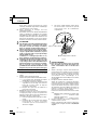
6. NEVER touch moving parts.
NEVER place your hands, fingers or
other body parts near the tool’s moving
parts.
7. NEVER operate without all guards in place.
NEVER operate this tool without all guards or
safety features in place and in proper working
order. If maintenance or servicing requires the
removal of a guard or safety feature, be sure to
replace the guard or safety feature before resuming
operation of the tool.
8. Use right tool.
Don’t force small tool or attachment to do the job
of a heavy-duty tool.
Don’t use tool for purpose not intended —for
example— don’t use circular saw for cutting tree
limbs or logs.
9. NEVER use a power tool for applications other
than those specified.
NEVER use a power tool for applications other than
those specified in the Instruction Manual.
10. Handle tool correctly.
Operate the tool according to the instructions
provided herein. Do not drop or throw the tool.
NEVER allow the tool to be operated by children,
individuals unfamiliar with its operation or
unauthorized personnel.
11. Keep all screws, bolts and covers tightly in place.
Keep all screws, bolts, and plates tightly mounted.
Check their condition periodically.
12. Do not use power tools if the plastic housing or
handle is cracked.
Cracks in the tool’s housing or handle can lead to
electric shock. Such tools should not be used until
repaired.
13. Blades and accessories must be securely mounted
to the tool.
Prevent potential injuries to youself or others.
Blades, cutting implements and accessories which
have been mounted to the tool should be secure
and tight.
14. Keep motor air vent clean.
The tool’s motor air vent must be kept clean so
that air can freely flow at all times. Check for dust
build-up frequently.
15. NEVER use a tool which is defective or operating
abnormally.
If the tool appears to be operating unusually,
making strange noises, or otherwise appears
defective, stop using it immediately and arrange
for repairs by a Hitachi authorized service center.
16. NEVER leave tool running unattended. Turn power
off.
Don’t leave tool until it comes to a complete stop.
17. Carefully handle power tools.
Should a power tool be dropped or struck against
hard materials inadvertently, it may be deformed,
cracked, or damaged.
18. Do not wipe plastic parts with solvent.
Solvents such as gasoline, thinner benzine, carbon
tetrachloride, and alcohol may damage and crack
plastic parts. Do not wipe them with such solvents.
Wipe plastic parts with a soft cloth lightly
dampened with soapy water and dry thoroughly.
19. NEVER use a depressed center wheel which is
cracked or deformed or worn away (see the
MAINTENANCE AND INSPECTION section on page
18).
20. NEVER use the grinder in places where the sparks
generated by the grinder can cause explosion, such
as where flammable materials or gases are
present.
21. NEVER push in the push button while the spindle
is running.
22. ALWAYS wear eye protection that meets the
requirement of the latest revision of
ANSI Standard Z87.1.
01Eng_G14DSL_US 8/28/13, 16:277

English
8
23. ALWAYS wear a mank or respirator to protect
yourself from dust or potentially harmful particles
generated during the grinding operation.
24. ALWAYS firmly grip the body handle and side
handle while operating the grinder.
25. ALWAYS have a trial run before grinding
commence. (see Test the grinder before using on
page 15).
26. ALWAYS follow the instructions contained in this
manual when replacing the depressed center
wheel.
27. ALWAYS be careful with buried objict such as an
underground wiring.
Touching these active wiring or electric cable with
this tool, you may receive an electric shock.
Comfirm if there are any buried object such as
electric cable within the wall, floor or ceiling where
you are going to operate here after.
28. Definitions for symbols used on this tool
V ............... volts
—
---
.............. direct current
Hz ............. hertz
A ............... amperes
no ............ no load speed
---/min ...... revolutions or reciprocation per minute
IMPORTANT SAFETY INSTRUCTIONS FOR
BATTERY CHARGER
WARNING:
Death or serious bodily injury could result from
improper or unsafe use of battery chargers. To avoid
these risks, follow these basic safety instructions:
READ ALL INSTRUCTIONS
1. This manual contains important safety and
operating instructions for battery charger Model
UC18YRSL/UC18YFSL.
2. Before using battery charger, read all instructions
and cautionary markings on (1) battery charger,
(2) battery, and (3) product using battery.
3. To reduce risk of injury, charge HITACHI
rechargeable battery type BSL1430 and BSL1830.
Other type of batteries may burst causing personal
injury and damage.
4. Do not expose battery charger to rain or snow.
5. Use of an attachment not recommended or sold
by the battery charger manufacturer may result in
a risk of fire, electric shock, or injury to persons.
6. To reduce risk of damage to electric plug and cord,
pull by plug when disconnecting battery charger.
7. Make sure cord is located so that it will not be
stepped on, tripped over, or otherwise subjected
to damage or stress.
8. An extension cord should not be used unless
absolutely necessary. Use of improper extension
cord could result in a risk of fire and electric shock.
If extension cord must be used make sure:
a. That blades of extension cord are the same
number, size, and shape as those of plug on
battery charger:
b. That extension cord is properly wired and in
good electrical condition; and
c. That wire size is large enough for AC ampere
rating of battery charger as specified in
Table 1.
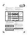
Table 1
RECOMMENDED MINIMUM AWG SIZE FOR
EXTENSION CORDS FOR BATTERY CHARGERS
AC Input Rating Amperes* AWG Size of Cord
Equal to or but less Length of Cord, Feet (Meter)
greater than than 25 (7.5) 50 (15) 100 (30) 150 (45)
0 2 18 18 18 16
2 3 18 18 16 14
3 4 18 18 16 14
* If the input rating of a battery charger is given in
watts rather than in amperes, the corresponding
ampere rating is to be determined by dividing the
wattage rating by the voltage rating–for example:
1,250 watts
125 volts
= 10 amperes
9. Do not operate battery charger with damaged cord
or plug-replace them immediately.
10. Do not operate battery charger if it has received a
sharp blow, been dropped, or otherwise damaged
in any way; take it to a qualified serviceman.
11. Do not disassemble battery charger; take it to a
qualified serviceman when service or repair is
required. Incorrect reassembly may result in a risk
of electric shock or fire.
12. To reduce risk of electric shock, unplug charger
from receptacle before attempting any
maintenance or cleaning. Removing the battery
will not reduce this risk.
01Eng_G14DSL_US 8/28/13, 16:278

English
9
IMPORTANT SAFETY INSTRUCTIONS FOR
USE OF THE BATTERY AND BATTERY
CHARGER
You must charge the battery before you can use the
power tool. Before using the model
UC18YRSL/UC18YFSL battery charger, be sure to read
all instructions and cautionary statements on it, the
battery and in this manual.
CAUTION:
USE ONLY HITACHI BATTERY TYPE BSL1430 AND
BSL1830. OTHER TYPES OF BATTERIES MAY
BURST AND CAUSE INJURY!
Follow these instructions to avoid the risk of injury:
WARNING:
Improper use of the battery or
battery charger can lead to serious
injury. To avoid these injuries:
1. NEVER disassemble the battery.
2. NEVER incinerate the battery, even if it is
damaged or is completely worn out. The
battery can explode in a fire.
3. NEVER short-circuit the battery.
4. NEVER insert any objects into the battery
charger’s air vents. Electric shock or
damage to the battery charger may
result.
5. NEVER charge outdoors. Keep the battery away
from direct sunlight and use only where
there is low humidity and good
ventilation.
6. NEVER charge when the temperature is below
32°F (0°C) or above 104°F (40°C).
7. NEVER connect two battery chargers together.
8. NEVER insert foreign objects into the hole for
the battery or the battery charger.
9. NEVER use a booster transformer when
charging.
10. NEVER use an engine generator or DC power to
charge.
11. NEVER store the battery or battery charger in
places where the temperature may reach
or exceed 104°F (40°C).
12.
ALWAYS
operate charger on standard household
electrical power (120 volts). Using the
charger on any other voltage may
overheat and damage the charger.
13.
ALWAYS
wait at least 15 minutes between
charges to avoid overheating the
charger.
14.
ALWAYS
disconnect the power cord from its
receptacle when the charger is not in
use.
CAUTION ON LITHIUM-ION BATTERY
To extend the lifetime, the lithium-ion battery equips
with the protection function to stop the output.
In the cases of 1 to 3 described below, when using this
product, even if you are pulling the switch, the motor
may stop. This is not the trouble but the result of
protection function.
1. When the battery power remaining runs out, the
motor stops.
In such case, charge it up immediately.
2. If the tool is overloaded, the motor may stop. In
this case, release the switch of tool and eliminate
causes of overloading. After that, you can use it
again.
3. If the battery is overheated under overload work,
the battery power may stop.
In this case, stop using the battery and let the
battery cool. After that, you can use it again (only
BSL1830).
Furthermore, please heed the following warning and
caution.
WARNING
In order to prevent any battery leakage, heat generation,
smoke emission, explosion and ignition beforehand,
please be sure to heed the following precautions.
1. Make sure that swarf and dust do not collect on
the battery.
䡬
During work make sure that swarf and dust do not
fall on the battery.
䡬
Make sure that any swarf and dust falling on the
power tool during work do not collect on the
battery.
䡬
Do not store an unused battery in a location
exposed to swarf and dust.
䡬
Before storing a battery, remove any swarf and
dust that may adhere to it and do not store it
together with metal parts (screws, nails, etc.).
2. Do not pierce battery with a sharp object such as a
nail, strike with a hammer, step on, throw or
subject the battery to severe physical shock.
3. Do not use an apparently damaged or deformed
battery.
4. Do not use the battery in reverse polarity.
5. Do not connect directly to an electrical outlets or
car cigarette lighter sockets.
6. Do not use the battery for a purpose other than
those specified.
7. If the battery charging fails to complete even when
a specified recharging time has elapsed,
immediately stop further recharging.
8. Do not put or subject the battery to high
temperatures or high pressure such as into a
microwave oven, dryer, or high pressure container.
9. Keep away from fire immediately when leakage
or foul odor are detected.
10. Do not use in a location where strong static
electricity generates.
01Eng_G14DSL_US 8/28/13, 16:279

English
10
11. If there is battery leakage, foul odor, heat
generated, discolored or deformed, or in any way
appears abnormal during use, recharging or
storage, immediately remove it from the
equipment or battery charger, and stop use.
CAUTION
1. If liquid leaking from the battery gets into your
eyes, do not rub your eyes and wash them well
with fresh clean water such as tap water and
contact a doctor immediately.
If left untreated, the liquid may cause eye-
problems.
2. If liquid leaks onto your skin or clothes, wash well
with clean water such as tap water immediately.
There is a possibility that this can cause skin
irritation.
SAVE THESE INSTRUCTIONS
AND
MAKE THEM AVAILABLE TO OTHER USERS
AND
OWNERS OF THIS TOOL!
3. If you find rust, foul odor, overheating, discolor,
deformation, and/or other irregularities when using
the battery for the first time, do not use and return
it to your supplier or vendor.
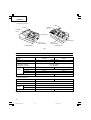
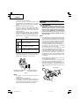
WARNING:
If an electrically conductive foreign object enters the
terminals of the lithium ion battery, a short-circuit may
occur resulting in the risk of fire. Please observe the
following matters when storing the battery.
䡬
Do not place electrically conductive cuttings, nails,
steel wire, copper wire or other wire in the storage
case.
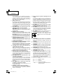
䡬
Either install the battery in the power tool or store
by securely pressing into the battery cover until
the ventilation holes are concealed to prevent
short-circuits (See Fig. 1).
01Eng_G14DSL_US 8/28/13, 16:2710

English
11
FUNCTIONAL DESCRIPTION
NOTE:
The information contained in this Instruction Manual is designed to assist you in the safe operation and
maintenance of the power tool.
NEVER operate, or attempt any maintenance on the tool unless you have first read and understood all safety
instructions contained in this manual.
Some illustrations in this Instruction Manual may show details or attachments that differ from those on your
own power tool.
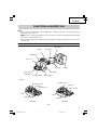
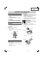
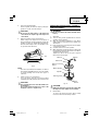
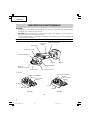
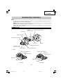
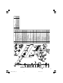
NAME OF PARTS
1. Cordless Disc Grinder (G14DSL / G18DSL)
䡬
Battery
Gear cover
Packing gland
Switch
Housing
Side handle
Brush cap
Wheel guard
Depressed
center wheel
Push button
Nameplate
Battery
Fig.1
Battery
Latch
Ventilation holes
Terminals
Battery cover
<BSL1830>
Battery
Latch
Ventilation holes
Terminals
Battery cover
<BSL1430>
01Eng_G14DSL_US 8/28/13, 16:2711

English
12
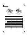
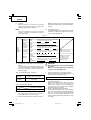
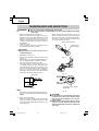
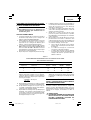
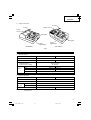
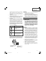
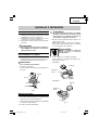
2. Battery Charger
Fig. 2
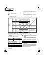
NOTE: The charging time may vary according to ambient temperature and power source voltage.
2. Battery Charger
Pilot lamp
Cord
Nameplate
Guide rail
Model UC18YRSL UC18YFSL
Input power source Single phase: AC 120 V 60 Hz
Charging time Approx. 45 min.
Charger
Charging voltage DC 14.4 V 18 V
Charging current DC 3.5 A
Weight 1.3 lbs. (0.6 kg) 1.1 lbs. (0.5 kg)
SPECIFICATIONS
1. Cordless Dise Grinder
Model G14DSL G18DSL
Motor DC motor
No-Load Speed 9,300/min 9,100/min
Wheel Size:
external diam. 4-1/2" (115 mm)
hole diam. 7/8" (22 mm)
Model BSL 1430 BSL 1830
Type Lithium – ion battery
Battery
Voltage DC 14.4V DC 18V
Capacity 3.0 Ah
Weight 3.7 lbs (1.7 kg) 4.0 lbs (1.8 kg)
Pilot lamp
Cord
Nameplate
Guide rail
<UC18YRSL> <UC18YFSL>
01Eng_G14DSL_US 8/28/13, 16:2712

English
13
APPLICATIONS
䡬
Removal of casting fin and finishing of various type
of steel, bronze and aluminum materials and
castings.
䡬
Grinding of welded sections or sections cut by
means of an acetylene torch.
䡬
Grinding of synthetic resins, slate, brick, marble.
WARNING:
To avoid the risk of serious injury, NEVER use this
grinder with cup wheels and/or saw blades.
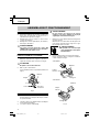
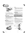
REMOVAL AND INSTALLATION METHOD
OF BATTERY
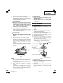
1. Battery removal
Hold the handle tightly and push the battery latch
to remove the battery (see Fig. 3).
CAUTION
Never short-circuit the battery.
2. Battery installation
Insert the battery while observing its polarities (see
Fig. 3).
Fig. 3
CHARGING METHOD
NOTE:
Before plugging into the receptacle, make sure the
following points.
䡬
The power source voltage is stated on the
nameplate.
䡬
The cord is not damaged.
ASSEMBLY AND OPERATION
Latch
Battery
Pull out
Insert
Push
WARNING:
Do not charge at voltage higher than indicated on
the nameplate.
If charged at voltage higher than indicated on the
nameplate, the charger will burn up.
1. Connect the charger’s power cord to a receptacle.
When the power cord is connected, the charger’s
pilot lamp will blink in red. (At 1-second intervals)
WARNING:
Do not use the electrical cord if
damaged. Have it repaired
immediately.
2. Insert the battery to the battery charger.
Insert the battery into the battery charger as shown
in Fig. 4, 5.
<UC18YRSL>
Fig. 4
<UC18YFSL>
Fig. 5
Battery
Charger
Pilot lamp
Battery
Charger
Pilot lamp
01Eng_G14DSL_US 8/28/13, 16:2713

English
14
3. Charging
When the battery is connected to the battery
charger, charging will commence and the pilot
lamp will light in red. (See Table 2)
NOTE:
If the pilot lamp flikers in red, pull out the plug
from the receptacle and check if the battery is
properly mounted.
(2) Regarding the temperature of the rechargeable
battery.
The temperatures for rechargeable batteries are
as shown in the Table 3, and batteries that have
become hot should be cooled for a while before
being recharged.
(3) Regarding recharging time (At 68°F (20°C))
Table 4 Charging time (At 20°C)
NOTE:
The charging time may vary according to
temperature and power source voltage.
4. Disconnect battery charger from the receptacle.
Table 3 Recharging ranges of batteries
Rechargeable Temperatures at which the
batteries battery can be recharged
BSL1430, 32°F–104°F
BSL1830 (0°C–40°C)
Charger
UC18YRSL / UC18YFSL
Battery
BSL1430, BSL1830 Approx. 45 min.
CAUTION
●
Do not pull the plug out of the receptacle by pulling
on the cord.
Make sure to grasp the plug when removing from
receptacle to avoid damaging cord.
5. Remove the battery from the battery charger.
Supporting the battery charger with hand, pull out
the battery from the battery charger.
How to make the batteries perform longer
(1) Recharge the batteries before they become
completely exhausted.
When you feel that the power of the tool becomes
weaker, stop using the tool and recharge its
battery. If you continue to use the tool and exhaust
the electric current, the battery may be damaged
and its life will become shorter.
(2) Avoid recharging at high temperatures.
A rechargeable battery will be hot immediately
after use. If such a battery is recharged immediately
after use, its internal chemical substance will
deteriorate, and the battery life will be shortened.
Leave the battery and recharge it after it has cooled
for a while.
When the battery is fully charged, the pilot lamp
will blink in red slowly. (At 1-second intervals) (See
Table 2)
(1) Pilot lamp indication
The indications of the pilot lamp will be as shown
in Table 2, according to the condition of the charger
or the rechargeable battery.
Table 2
Indications of the pilot lamp
Lights for 0.5 seconds. Does not light for 0.5
seconds. (off for 0.5 seconds)
Lights continuously
Lights for 0.5 seconds. Does not light for 0.5
seconds. (off for 0.5 seconds)
Lights for 0.1 seconds. Does not light for 0.1
seconds. (off for 0.1 seconds)
Lights continuously
Lights for 1 secods. Does not light for 0.5
seconds. (off for 0.5 seconds)
Before
charging
While
charging
Charging
complete
Charging
impossible
Blinks
(red)
Lights
(red)
Blinks
(red)
Flickers
(red)
Lights
(green)
<UC18YRSL>
Blinks
(red)
<UC18YFSL>
Malfunction in the
battery or the charger
Battery overheated.
Unable to charge
(Charging will
commence when
battery cools).
Overheat
standby
The
pilot
lamp
lights or
blinks.
01Eng_G14DSL_US 8/28/13, 16:2714

English
15
CAUTION
●
When the battery charger has been continuosly
used, the battery charger will be heated, thus
constituting the cause of the failures. Once the
charging has been completed, give 15 minutes rest
until the next charging.
●
If the battery is rechraged when it is warm due to
battery use or exposure to sunlight, the pilot lamp
may light in green.
The battery will not be recharged. In such a case,
let the battery cool before charging.
●
When the pilot lamp flikers rapidly in red (at 0.2–
second intervals), check for and take out any
foreign objects in the charger’s battery installation
hole. If there are no foreign objects, it is probable
that the battery or charger is malfunctioning. Take
it to your authorized Service Center.
PRIOR TO OPERATION
1. Power switch
Ensure that the switch is in the OFF position.
2. Check your work environment
Ensure the following before operation:
䡬
No flammable gas, liquid, or object at
worksite.
䡬
When grinding thin steel sheet it may cause
a high booming noise.
To avoid such noise, place a rubber mat under
the workpiece.
䡬
Clear the area of children or unauthorized
personnel.
3. Mounting the wheel guard
Be sure to mount the wheel guard at an angle that
will protect the operator’s body from injury by a
broken wheel piece.
[Installing Wheel Guard]
䡬
Slightly loosen the screw on the wheel guard.
䡬
Install the wheel guard to the packing gland,
turn it to the angle suitable for operation, and
make adjustment.
䡬
After the adjustment, ensure that the screw
is securely tightened on the wheel guard in
order to fix it completely.
WARNING:
If the wheel guard is not attached properly, a
broken wheel may result in and cause death or
serious injury.
4. Thoroughly check that the depressed center wheel
is free of cracks, splits and other abnomalities
before mounting. Make sure it is firmly clamped
and has been properly mounted. Refer to page 17
of this manual for Depressed Center Wheel
Assembly and Disassembly
5. Test the grinder before using.
Before actually beginning the grinding work, test
the grinder by first clearing the area of all other
personnel. Make sure the wheel guard is in place
and that you are wearing eye protection. Turn the
grinder “on”, and make sure the grinder runs
smoothly and shows no abnormalities.
Duration of the trial run is as follows:
When depressed center wheel
is replaced ............................... 3 minutes or
more
When starting daily work ...... 1 minute or
more
6. Use only properly rated depressed center wheels.
Use only depressed center wheels rated at 13,300
RPM or more.
Using a depressed center wheel rated less can lead
to wheel disintegration during operation and cause
serious bodily injury.
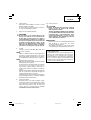
7. Check the push button.
Make sure that the push button is disengaged by
pushing push button two or three times before
turning on the grinder. (Fig. 8)
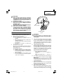
8. About Remaining Battery Indicator
When pressing the remaining battery indicator
switch, the remaining battery indicator lamp lights
and the battery remaining power can be checked.
Fig. 5
Wheel guard
Packing gland
01Eng_G14DSL_US 8/28/13, 16:2715

English
16
(Fig.6) When releasing your finger from the
remaining battery indicator switch, the remaining
battery indicator lamp goes off. The table 5 shows
the state of remaining battery indicator lamp and
the battery remaining power.
As the remaining battery indicator shows
somewhat differently depending on ambient
temperature and battery characteristics, read it as
a reference.
Fig. 6
NOTE:
䡬
Do not give a strong shock to the switch panel or
break it.It may lead to a trouble.
䡬
To save the battery power consumption, the
remaining battery indicator lamp lights while
pressing the remaining battery indicator switch.
GRINDER OPERATION
CAUTION:
To extend the lifetime, the lithium-ion battery
equips with the protection function to stop the
output. Therefore, if the tool is overloaded, the
motor may stop. However, this is not the trouble
but the result of protection function. In this case,
release the switch of tool and eliminate the causes
of overloading.
NOTE:
䡬
To prevent injuries, this product has a function that
prevents unexpected motor rotation when the
battery is inserted. The motor will not run if the
battery is inserter while the switch is still ON. After
installing the battery, turn the switch off and then
back on again.
䡬
The G14DSL and G18DSL models are equipped
with a protection function that will shut down the
tool in the event of an overload.
Should the tool shut down due to an overload, turn
the power off and then turn it back on again.
An overload that stops tool operation and lasts
more than 10 seconds may not be released by
turning the power off and on. Should this happen,
remove the battery from the tool and reinstall it
before turning on the power switch.
1. Hold the grinder firmly by its housing and side
handle (Fig. 1).
The grinder produces a counterforce which must
be controlled by firmly holding onto the grinder.
2. Turn the grinder “on”. (Fig. 7)
While holding the grinder firmly, use one finger to
slide the switch to the “on” position.
3. Use light grinding pressure.
There is no need to press hard when grinding.
Usually the grinder’s own weight is sufficient to
allow the required light contact with the surface to
be ground.
WARNING:
Do not press the grinder forcibly against the
surface to be ground. Heavy pressure can result
in wheel breakage and serious injury. It can also
damage the surface being ground or damage the
grinder’s motor.
State of lamp Battery Remaining Power
The battery remaining power
is enough.
The battery remaining power
is a half.
The battery remaining power
is nearly empty.
Re-charge the battery soonest
possible.
Table 5
Remaining battery
indicator lamp
Remaining battery
indicator switch
Fig. 7
Switch
ON OFF
01Eng_G14DSL_US 8/28/13, 16:2716

English
17
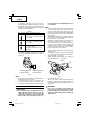
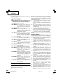
4. Use proper grinding angle.
Grind only with the wheel’s edge by lifting the
grinder 15° to 30°, as shown in Fig. 8.
CAUTION:
Do not use the entire surface of the depressed
center wheel. Use only the edge of the depressed
center wheel.
5. Move the grinder in the proper direction.
When using a new depressed center wheel in
direction A (Fig. 8), the wheel edge may cut into the
workpiece. In this case, grind in direction B (Fig. 8).
Once the wheel edge is worn, the workpiece can
be ground in both directions.
Fig. 8
NOTE:
The wheel provided (resinoid wheel) is rated as
Class A grain and # 36 grain size. It is most suitable
for heavy grinding of steel and other types of
materials.
6. Adjust operation to desired finish.
For a fine finish, decrease pressure by lifting
slightly. Grind slowly and at the appropriate speed.
CAUTION:
The revolving depressed center wheel will create
air turbulence.
Do no lay the grinder down in areas of dust or dirt
until it has come to a complete stop.
DEPRESSED CENTER WHEEL ASSEMBLY
AND DISASSEMBLY
WARNING:
Be sure to turned off the switch and pull out the
battery.
1. Assembly
(1) Turn the disc grinder upsidedown so that the
spindle is facing upward.
(2) Align the oval-shaped indentation of the wheel
washer with the notched part of the spindle, then
attach them.
(3) Fit the protuberance of the depressed center wheel
onto the wheel washer.
(4) Screw the wheel nut onto the spindle.
(5) While pushing the push button with one hand, lock
the spindle by turning the depressed center wheel
slowly with the other hand.
Tighten the wheel nut by using the supplied
wrench as shown in Fig. 9.
CAUTION:
Tighten the wheel nut securely and confirm that
the depressed center wheel does not wobble.
2. Disassembly
To remove the depressed center wheel, simply
reverse the above-mentioned procedure.
Depressed center
wheel
Push
button
Wrench
Wheel guard
Wheel washer
Spindle
Wheel nut
Fig. 9
Tighten
15° – 30°
AB
01Eng_G14DSL_US 8/28/13, 16:2717

English
18
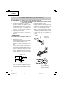
When installing the carbon brush, choose the
direction so that the nail of the carbon brush agrees
with the contact portion outside the brush tube.
Then push it in with a finger as illustrated in Fig.
13. Lastly, install the brush cap.
Fig. 12
CAUTION:
●
Be absolutely sure to insert the nail of the carbon
brush into the contact portion outside the brush
tube. (You can insert whichever one of the two
nails provided.)
●
Caution must be exercised since any error in this
operation can result in the deformed nail of the
carbon brush and may cause motor trouble at an
early stage.
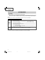
MAINTENANCE AND INSPECTION
WARNING: 䢇
Be sure to turned off the switch and pull out the battery.
䢇
Using cracked, deformed or damaged wheels can lead to wheel breakage and resulting
serious injury.
1. Replacing the depressed center wheel
Replace the depressed center wheel when it has
been worn out to about 2-3/8" (60mm) in external
diameter. Confirm that there is no crack or any
damage to the depressed center wheel. If there is
a crack or a transformation in the wheel, replace it
immediately.
2. Check the Screws
Loose screws are dangerous. Regularly inspect
them and make sure they are tight.
CAUTION:
Using this power tool with loosened screws is
extremely dangerous.
3. Maintenance of the motor
The motor unit winding is the very “heart” of the
power tool.
Exercise due care to ensure the winding does not
become damaged and/or wet with oil or water.
4. Inspecting the carbon brushes (Fig. 10)
The motor employs carbon brushes which are
consumable parts. Since and excessively worn
carbon brush can result in motor trouble, replace
the carbon brush with new ones when it becomes
worn to or near the “wear limit”. In addition,
always keep carbon brushes clean and ensure that
they slide freely within the brush holders.
NOTE:
When replacing the carbon brush with a new one,
be sure to use the Hitachi Carbon Brush Code No.
999054.
5. Replacing carbon brushes
Take out the carbon brush by first removing the
brush cap and then hooking the protrusion of the
carbon brush with a flat head screw driver, etc., as
shown in Fig. 12.
Fig. 10
Wear limit
0.12" (3 mm)
0.45"
(11.5 mm)
Fig. 11
Nail of carbon brush
Protrusion of
carbon brush
Fig. 13
Contact portion outside
brush tube
01Eng_G14DSL_US 8/28/13, 16:2718

English
19
6. Check for Dust
Dust may be removed with a soft cloth or a cloth
dampened with soapy water.
Do not use bleach, chlorine, gasoline or thinner,
for they may damage the plastics.
7. Disposal of the exhausted battery
WARNING:
Do not dispose of the exhausted battery. The
battery must explode if it is incinerated. The
product that you have purchased contains a
rechargeable battery. The battery is recyclable. At
the end of it’s useful life, under various state and
local laws, it may be illegal to dispose of this
battery into the municipal waste stream. Check
with your local solid waste officials for details in
your area for recycling options or proper disposal.
8. Storage
Storing in a place below 104°F (40°C) and out of
the reach of children.
NOTE:
Make sure that the battery is fully charged when
stored for a long period (3 months or more). The
battery with smaller capacity may not be able to
be charged when used, if stored for a long period.
NOTE:
Storing lithium-ion batteries
Make sure the lithium-ion batteries have been fully
charged before storing them.
Prolonged storage of batteries with a low charge
may result in performance deterioration,
significantly reducing battery usage time or
rendering the batteries incapable of holding a
charge.
However, significantly reduced battery usage time
may be recovered by repeatedly charging and
using the batteries two to five times.
If the battery usage time is extremely short despite
repeated charging and use, consider the batteries
dead and purchase new batteries.
9. Service and repairs
All quality power tools will eventually require
servicing or replacement of parts because of wear
from normal use. To assure that only authorized
replacement parts will be used, all service and
repairs must be performed by a HITACHI
AUTHORIZED SERVICE CENTER, ONLY.
10. Service parts list
CAUTION:
Repair, modification and inspection of Hitachi
Power Tools must be carried out by an Hitachi
Authorized Service Center.
This Parts List will be helpful if presented with the
tool to the Hitachi Authorized Service Center when
requesting repair or other maintenance. In the
operation and maintenance of power tools, the
safety regulations and standards prescribed in
each country must be observed.
MODIFICATIONS:
Hitachi Power Tools are constantly being improved
and modified to incorporate the latest
technological advancements.
Accordingly, some parts (i.e. code numbers and/
or design) may be changed without prior notice.
Important notice on the batteries for the Hitachi
cordless power tools
Please always use one of our designated genuine
batteries. We cannot guarantee the safety and
performance of our cordless power tool when
used with batteries other than these designated
by us, or when the battery is disassembled and
modified (such as disassembly and replacement
of cells or other internal parts).
01Eng_G14DSL_US 8/28/13, 16:2719

English
20
ACCESSORIES
WARNING:
Never use any accessories other than those mentioned below.
The use of any accessories other than those mentionded below or attachments not intended for use such as
cup wheel, cut-off wheel or saw blade is dangerous and may cause personal injury or property damage.
NOTE:
Accessories are subject to change without any obligation on the part of the HITACHI.
STANDARD ACCESSORIES
NOTE:
Specifications are subject to change without any obligation on the part of the HITACHI.
䡬
Depressed center wheel ................................................................................................. 1
4-1/2" (115 mm) external dia. × 1/4" (6 mm) thickness × 7/8"" (22 mm) hole dia
(Code No. 701045 or 326203)
䡬
Wrench (Code No. 938332Z) .......................................................................................... 1
䡬
Side handle (Code No. 318312) ..................................................................................... 1
䡬
Battery charger (UC18YRSL or UC18YFSL) .................................................................. 2
䡬
Battery (BSL1430 : G14DSL) .......................................................................................... 2
(BSL1830 : G18DSL) .......................................................................................... 1
䡬
Battery cover (Code No. 329897) (only G14DSL) ......................................................... 1
䡬
Plastic Case (Code No. 328206) ..................................................................................... 1
Battery, battery charger, plastic case and battery cover are not contained.
G14DSL
(2LSCK)
G18DSL
(LSCK)
G14DSL
G18DSL
(NN)
01Eng_G14DSL_US 8/28/13, 16:2720
La page charge ...
La page charge ...
La page charge ...
La page charge ...
La page charge ...
La page charge ...
La page charge ...
La page charge ...
La page charge ...
La page charge ...
La page charge ...
La page charge ...
La page charge ...
La page charge ...
La page charge ...
La page charge ...
La page charge ...
La page charge ...
La page charge ...
La page charge ...
La page charge ...
La page charge ...
La page charge ...
La page charge ...
La page charge ...
La page charge ...
La page charge ...
La page charge ...
La page charge ...
La page charge ...
La page charge ...
La page charge ...
La page charge ...
La page charge ...
La page charge ...
La page charge ...
La page charge ...
La page charge ...
La page charge ...
La page charge ...
-
 1
1
-
 2
2
-
 3
3
-
 4
4
-
 5
5
-
 6
6
-
 7
7
-
 8
8
-
 9
9
-
 10
10
-
 11
11
-
 12
12
-
 13
13
-
 14
14
-
 15
15
-
 16
16
-
 17
17
-
 18
18
-
 19
19
-
 20
20
-
 21
21
-
 22
22
-
 23
23
-
 24
24
-
 25
25
-
 26
26
-
 27
27
-
 28
28
-
 29
29
-
 30
30
-
 31
31
-
 32
32
-
 33
33
-
 34
34
-
 35
35
-
 36
36
-
 37
37
-
 38
38
-
 39
39
-
 40
40
-
 41
41
-
 42
42
-
 43
43
-
 44
44
-
 45
45
-
 46
46
-
 47
47
-
 48
48
-
 49
49
-
 50
50
-
 51
51
-
 52
52
-
 53
53
-
 54
54
-
 55
55
-
 56
56
-
 57
57
-
 58
58
-
 59
59
-
 60
60


Hitachi G 18DSL Safety Instructions And Instruction Manual
- Catégorie
- Outils électroportatifs
- Taper
- Safety Instructions And Instruction Manual
- Ce manuel convient également à
dans d''autres langues
- English: Hitachi G 18DSL
- español: Hitachi G 18DSL
Documents connexes
-
Hitachi CJ 14DSL Manuel utilisateur
-
Hitachi DV18DSL Manuel utilisateur
-
-
-
-
Hitachi WH 18DBDL Manuel utilisateur
-
-
-
-
Autres documents
-
Hikoki DS18DE Manuel utilisateur
-
Skil AG290202 Le manuel du propriétaire
-
DeWalt DWE4001 Manuel utilisateur
-
DeWalt D28492 Le manuel du propriétaire
-
Worx WX812L Le manuel du propriétaire
-
Ryobi P421 Le manuel du propriétaire
-
Ryobi P423 Manuel utilisateur
-
-
 BORMANN PRO BBP3500 Cordless Angle Grinder 20v Manuel utilisateur
-
Hikoki P18DSL Manuel utilisateur
