Amprobe AC75B Manuel utilisateur
- Catégorie
- Multimètres
- Taper
- Manuel utilisateur
Ce manuel convient également à

C
M
Y
CM
MY
CY
CMY
K
AC75Bman_cover [Converted] copy.Page 1 8/18/2006 10:50:59 AM

AC75B
AC Digital Clamp Multimeter
Users Manual
• Mode d’emploi
• Bedienungshandbuch
• Manuale d’Uso
• Manual de uso
PN 2729024
July 2006
©2006 Amprobe® Test Tools.
All rights reserved. Printed in Taiwan


AC75B
AC Digital Clamp Multimeter
Users Manual
English

Limited Warranty and Limitation of Liability
Your Amprobe® product will be free from defects in material and
workmanship for 1 year from the date of purchase. This warranty does not
cover fuses, disposable batteries or damage from accident, neglect, misuse,
alteration, contamination, or abnormal conditions of operation or handling.
Resellers are not authorized to extend any other warranty on Amprobe®’s
behalf. To obtain service during the warranty period, return the product with
proof of purchase to an authorized Amprobe® Test Tools Service Center or
to a Amprobe® dealer or distributor. See Repair Section above for details.
THIS WARRANTY IS YOUR ONLY REMEDY. ALL OTHER WARRANTIES -
WHETHER EXPRESS, IMPLIED OR STAUTORY - INCLUDING IMPLIED
WARRANTIES OF FITNESS FOR A PARTICULAR PURPOSE OR
MERCHANTABILITY, ARE HEREBY DISCLAIMED. MANUFACTURER SHALL
NOT BE LIABLE FOR ANY SPECIAL, INDIRECT, INCIDENTAL OR
CONSEQUENTIAL DAMAGES OR LOSSES, ARISING FROM ANY CAUSE OR
THEORY. Since some states or countries do not allow the exclusion or
limitation of an implied warranty or of incidental or consequential damages,
this limitation of liability may not apply to you.

1
AC75B Clamp-on Multimeter
Contents
Safety Information ........................................................................................2
Symbols Used in this Manual........................................................................3
Introduction ..................................................................................................4
Making Measurements...............................................................................4
Additional Features ....................................................................................4
Product Maintenance ....................................................................................4
Maintenance...............................................................................................4
Cleaning.....................................................................................................4
Troubleshooting.........................................................................................5
Battery Replacement..................................................................................5
Repair ...........................................................................................................6
Specifications................................................................................................7
General Specifications................................................................................7
Environmental Specifications.....................................................................7
Electrical Specifications .............................................................................7

2
Safety Information
To ensure safe operation and usage of the meter, follow these instructions.
Failure to observe warnings can result in severe injury or death.
• To avoid possible electric shock or personal injury, follow these
guidelines:
• Do not use the meter if it is damaged. Before you use the meter,
inspect the case. Look for cracks or missing plastic. Pay particular
attention to the insulation surrounding the connectors.
• Inspect the test leads for damaged insulation or exposed metal.
Check the test leads for continuity.
• Replace damaged test leads before you use the meter.
• If this product is used in a manner not specified by the
manufacturer, the protection provided by the equipment may be
impaired.
• Do not use the meter if it operates abnormally. Protection may be
impaired. When in doubt, have the meter serviced.
• Do not operate the meter around explosive gas, vapor, or dust.
• Do not apply more than the rated voltage, as marked on the meter,
between terminals or between any terminal and earth ground.
• Before use, verify the meter’s operation by measuring a known
voltage.
• When measuring current, turn off circuit power before connecting
the meter in the circuit. Remember to place the meter in series with
the circuit.
• Do not attempt to repair this meter. There are no user serviceable
parts.
• Use caution when working above 30 V ac rms, 42 V peak, or 60 V
dc. Such voltages pose a shock hazard.
• When using the probes, keep your fingers behind the finger guards
on the probes.
• Connect the common test lead before you connect the live test lead.
When you disconnect test leads, disconnect the live test lead first.
• Remove test leads from the meter before you open the battery door.
• Do not operate the meter with the battery door removed or
loosened.
• To avoid false readings, which could lead to possible electric shock
or personal injury, replace the batteries as soon as the low battery
indicator (N) appears.
• Only use a 9 Volt battery, properly installed in the meter case, to
power the meter.
• To avoid the potential for fire or electrical shock, do not connect the
thermocouple to electrically live circuits.
• Disconnect circuit power and discharge all high-voltage capacitors
before testing resistance,continuity, diodes, or capacitance.

3
Symbols Used in this Manual
N Battery W Refer to the manual
T Double insulated X Dangerous Voltage
F Direct Current J Earth Ground
B Alternating Current R Audible tone
; Conforms to relevant
Australian standards. )Canadian Standards
Association
(Canadian and US)
P Complies with EU
directives , Application around and
removal from HAZARDOUS
LIVE conductors is
permitted.

4
Introduction
The AC75B digital clamp-on multimeter, is a fully featured meter that also
measures temperature using a Type K probe (included). The AC75B has full
Category safety ratings and is CAT III, 600 V.
Making Measurements
Measurement Functions
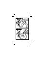
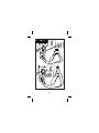
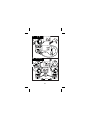
• AC and DC Volts (V/v) See Figure -4-
• Resistance (O) See Figure -5-
• Diode/Continuity (G/C) See Figure –6-
• DC Current (DC μA) See Figure –7-
• Capacitance (P) See Figure –8-
• Temperature (°C/°F) See Figure –9-
• AC Current (a) See Figure –11-
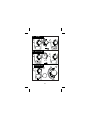
Additional Features
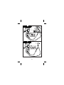
Auto Power Off/Auto Power Off Disable See Figures -2- and –3-
The meter will automatically shut itself off after approximately 10 minutes
after power is turned on, or no activity has occurred with the meter. The
meter will beep when it turns off. Turn the rotary dial to reactivate the
meter.
The Auto Power Off feature can be disabled to keep the meter from going to
sleep. Press the BACKLIGHT button and then switch the rotary knob to
power on the meter.
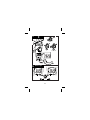
Backlight See Figure -12-
The AC75B backlight illuminates the entire display for easy measurement
viewing in dark work environments. The backlight is activated for 60
seconds once the button is pressed.
HOLD Measurements See Figure -10-
The HOLD button allows the meter to capture and continuously display a
measurement reading. To use the HOLD feature, make a measurement,
when the reading has stabilized, press the HOLD button. The measurement
value will be captured on the display. Press the HOLD button again to
release the value.
Product Maintenance
Maintenance
Do not attempt to repair this meter. It contains no user serviceable parts.
Repair or servicing should only be performed by qualified personnel.
Cleaning
To clean the meter, periodically wipe the case with a soft moistened cloth.
To avoid damage to the plastic components do not use benzene, alcohol,
acetone, ether, paint thinner, lacquer thinner, ketone or other solvents to
clean the meter.

5
Troubleshooting
If the meter appears to operate improperly, check the following items first.
1. Review the operating instructions to ensure the meter is being used
properly.
2. Make sure the battery is in good condition. The low battery symbol N
appears when the battery falls below the level where accuracy is
guaranteed. Replace a low battery immediately.
Battery Replacement
To replace the battery
1. Turn the meter off and remove the test leads.
2. Loosen the screw and remove the battery door.
3. Replace the battery using an alkaline 9 V battery. See General
Specifications for detailed battery specifications.
4. Replace the battery cover and tighten the screw. Recycle the battery
using approved methods.
XWWARNING
To avoid electrical, shock remove the test leads from both the meter and
the test circuit before accessing the battery or the fuses.

6
Repair
All test tools returned for warranty or non-warranty repair or for calibration
should be accompanied by the following: your name, company’s name,
address, telephone number, and proof of purchase. Additionally, please
include a brief description of the problem or the service requested and
include the test leads with the meter. Non-warranty repair or replacement
charges should be remitted in the form of a check, a money order, credit
card with expiration date, or a purchase order made payable to Amprobe®
Test Tools.
In-Warranty Repairs and Replacement – All Countries
Please read the warranty statement and check your battery before
requesting repair. During the warranty period any defective test tool can be
returned to your Amprobe® Test Tools distributor for an exchange for the
same or like product. Please check the “Where to Buy” section on
www.amprobe.com for a list of distributors near you. Additionally, in the
United States and Canada In-Warranty repair and replacement units can
also be sent to a Amprobe® Test Tools Service Center (see below for
address).
Non-Warranty Repairs and Replacement – US and Canada
Non-warranty repairs in the United States and Canada should be sent to a
Amprobe® Test Tools Service Center. Call Amprobe® Test Tools or inquire
at your point of purchase for current repair and replacement rates.
In USA In Canada
Amprobe® Test Tools Amprobe® Test Tools
Everett, WA 98203 Mississauga, ON L4Z 1X9
Tel: 888-993-5853 Tel: 905-890-7600
Fax: 425-446-6390 Fax: 905-890-6866
Non-Warranty Repairs and Replacement – Europe
European non-warranty units can be replaced by your Amprobe® Test Tools
distributor for a nominal charge. Please check the “Where to Buy” section
on www.amprobe.com for a list of distributors near you.
European Correspondence Address*
Amprobe® Test Tools Europe
P.O. Box 1186
5602 BD Eindhoven
The Netherlands
*(Correspondence only – no repair or replacement available from this
address. European customers please contact your distributor).

7
Specifications
General Specifications
Display: 3 ¾ digit large scale liquid crystal display (LCD)
Display Count: 4000 counts
Measuring Rate: 1.5 times per second
Overrange Display: 0o is displayed for Ω functions. Actual value is shown
for A, V, and temperature functions.
Automatic Power Off Time: Approximately 10 minutes after power on
Low battery indication: The N symbol is displayed when the battery
voltage drops below the operating level for accurate results.
Power: Single standard 9 V battery, NEDA160A.
Battery Life: 200 hours with an alkaline 9 V battery.
Environmental Specifications
Indoor Use
Calibration: One year calibration cycle
Operating Temperature:
0 °C to 30 °C at ≥80 % R.H.
30 °C to 40 °C at ≥75 % R.H.
40 °C to 50 °C at ≥45 % R.H.
Storage Temperature: -20 °C to 60 °C at 0 to 80 % R.H. (battery removed)
P, )
Overvoltage Category:
IEC 61010-1 CAT III - 600 V, CAT II 1000 V, Pollution Degree 2
EN61010-2-032
CAN/CSA C22.2 No. 1010.1-92
CAN/CSA C22.2 No. 1010.1B-92
CAN/CSA C22.2 No. 1010.2.032-96
Altitude: ≤2000 M (6562 Feet)
Conductor Size: ≤ 32 mm diameter (1.25 in)
EMC: EN61326-1.
Shock Vibration: Sinusoidal vibration per MIL-PRF-28800F (5 to 55 Hz, 3 g
maximum)
Drop Protection: 4 foot drop to hardwood on concrete floor
Electrical Specifications
Accuracy: ±(% reading + number of digits) at 23 °C ±5 °C at <80 % R.H.
Temperature Coefficient: Add 0.2 x (Specified Accuracy)/°C, <.18 °C,
>28 °C.

8
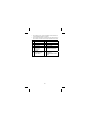
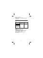
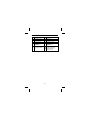
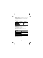
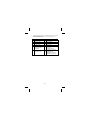
DC/AC VOLTS
Range DC Accuracy AC Accuracy
4.000 V
40.00 V
400.0 V
1000 V dc/750 V ac
±(0.9 % + 2 dgt)
±(1.5 % + 5 dgt)
50 Hz to 500 Hz
Overvoltage Protection: DC 1000 V or AC 750 V rms
Input Impedance: 10 MΩ//less than 100 ρF
CMRR/NMRR: (Common Mode Rejection Ratio/Normal Mode Rejection
Ratio)
V ac
CMRR > 60 dB at DC, 50 Hz/60 Hz
V dc
CMRR > 100 dB at DC, 50 Hz/60 Hz
NMRR > 50 dB at DC, 50 Hz/60 Hz
AC Conversion Type: Average sensing rms indication.
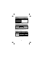
Resistance
Range Accuracy
2400.0 Ω ±(1.0 % + 2 dgt)
4.000 kΩ
40.00 kΩ
400.0 kΩ
±(0.7 % + 2 dgt)
4.000 MΩ ±(1.0 % + 2 dgt)
140.00 MΩ ±(1.5 % + 2 dgt)
Overload Protection: 1000 V dc/750 V ac
Open Circuit Voltage: -1.3 V approx.
1<100 dgt rolling
210 dgt rolling

9
Diode Check and Continuity
Resolution Accuracy
10 mV ±(1.5 % + 5 dgt)
From 0.4 V to 0.8 V
Max Test Current: 1.5 mA
Max Open Current: 3 V
Overload Protection: 1000 V dc/750 V ac
Continuity: Built-in buzzer sounds when resistance is less than
approximately 100 Ω. Response time is approximately 100 msec
DC μA
Range Accuracy
400.0 μA
4000 μA ±(1.0 % + 2 dgt)
Voltage Burden: < 5 mV/μA
Overload Protection: 1000 V dc/750 V ac
Resolution: 100 nA

10
Capacitance
Range Accuracy
4.000 nF ±(3.0 % + 20 dgt)
40.00 nF
400.0 nF
4.000 μF
40.00 μF
400.0 μF
14.000 mF
±(2.0 % + 8 dgt)
Overload Protection: 1000 V dc/750 V ac
1< 50 dgt fluctuating
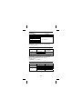
AC Current
Function Range AC Accuracy
0.0 to 399.9 A
AB
(50 to 60 Hz) 400.0 to 600.0 A* ±(1.9 % + 5 digits)
*0.0 to 500.0 A Continuous
501 A to 600.0 A 10 minutes maximum followed by 10 minutes cooling
period.
Overload Protection: 1000 V dc/750 V ac
AC Conversion Type: Average sensing rms display
Position Error: ±1.5 % of reading
Temperature
Function Range Accuracy
-40 °C to 0.1 °C 1 % ± 4 °C
°C 0 °C to 400.0 °C 1 % ± 3 °C
-40 °F to 32 °F 1 % ± 8 °F
32 °F to 750 °F 1 % ± 6 °F
°F
750 °F to 1000 °F 1 % ± 8 °F
Overload Protection: 1000 V dc/750 V ac

11
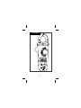
1
Clamp Meter
AC75B

12
2
3
Auto Power Off
Auto Off Disable
10 min
Off/On
2
1
AC75B

13
4
5Disconnect
AC75B
AC75B

14
6
AC75B
AC75B

15
7
8
Disconnect
Discharge
AC75B
AC75B
La page est en cours de chargement...
La page est en cours de chargement...
La page est en cours de chargement...
La page est en cours de chargement...
La page est en cours de chargement...
La page est en cours de chargement...
La page est en cours de chargement...
La page est en cours de chargement...
La page est en cours de chargement...
La page est en cours de chargement...
La page est en cours de chargement...
La page est en cours de chargement...
La page est en cours de chargement...
La page est en cours de chargement...
La page est en cours de chargement...
La page est en cours de chargement...
La page est en cours de chargement...
La page est en cours de chargement...
La page est en cours de chargement...
La page est en cours de chargement...
La page est en cours de chargement...
La page est en cours de chargement...
La page est en cours de chargement...
La page est en cours de chargement...
La page est en cours de chargement...
La page est en cours de chargement...
La page est en cours de chargement...
La page est en cours de chargement...
La page est en cours de chargement...
La page est en cours de chargement...
La page est en cours de chargement...
La page est en cours de chargement...
La page est en cours de chargement...
La page est en cours de chargement...
La page est en cours de chargement...
La page est en cours de chargement...
La page est en cours de chargement...
La page est en cours de chargement...
La page est en cours de chargement...
La page est en cours de chargement...
La page est en cours de chargement...
La page est en cours de chargement...
La page est en cours de chargement...
La page est en cours de chargement...
La page est en cours de chargement...
La page est en cours de chargement...
La page est en cours de chargement...
La page est en cours de chargement...
La page est en cours de chargement...
La page est en cours de chargement...
La page est en cours de chargement...
La page est en cours de chargement...
-
 1
1
-
 2
2
-
 3
3
-
 4
4
-
 5
5
-
 6
6
-
 7
7
-
 8
8
-
 9
9
-
 10
10
-
 11
11
-
 12
12
-
 13
13
-
 14
14
-
 15
15
-
 16
16
-
 17
17
-
 18
18
-
 19
19
-
 20
20
-
 21
21
-
 22
22
-
 23
23
-
 24
24
-
 25
25
-
 26
26
-
 27
27
-
 28
28
-
 29
29
-
 30
30
-
 31
31
-
 32
32
-
 33
33
-
 34
34
-
 35
35
-
 36
36
-
 37
37
-
 38
38
-
 39
39
-
 40
40
-
 41
41
-
 42
42
-
 43
43
-
 44
44
-
 45
45
-
 46
46
-
 47
47
-
 48
48
-
 49
49
-
 50
50
-
 51
51
-
 52
52
-
 53
53
-
 54
54
-
 55
55
-
 56
56
-
 57
57
-
 58
58
-
 59
59
-
 60
60
-
 61
61
-
 62
62
-
 63
63
-
 64
64
-
 65
65
-
 66
66
-
 67
67
-
 68
68
-
 69
69
-
 70
70
-
 71
71
-
 72
72


Amprobe AC75B Manuel utilisateur
- Catégorie
- Multimètres
- Taper
- Manuel utilisateur
- Ce manuel convient également à
dans d''autres langues
- italiano: Amprobe AC75B Manuale utente
- español: Amprobe AC75B Manual de usuario
- Deutsch: Amprobe AC75B Benutzerhandbuch
Documents connexes
-
Amprobe PM51A Pocket Multimeter Manuel utilisateur
-
Amprobe PM55A Manuel utilisateur
-
-
-
-
-
-