
Feature Information ..........................
Assembly .........................................
Installation ........................................
Gas Assist Lift Mechanism ...............
Operation .........................................
Adjustments .......................................
Cautions .............................................
Battery Information .............................
Battery Connection ..........................
Wiring Diagram ................................
Circuit Breaker ...................................
Propeller ..........................................
Maximizer™ .....................................
Maintenance ....................................
Trouble Shooting ..............................
Limited Warranty ..............................
Description.............................................. pg. 2
Assemblage ............................................ pg. 3
Pose ....................................................... pg. 4-5
Mécanisme de levage assisté .............. pg. 6-7
Fonctionnement ...................................... pg. 8-9
Reglages ................................................ pg. 10-11
Prudences .............................................. pg. 12
Informations de batterie .......................... pg. 13
Branchement de la batterie .................... pg. 14
Schéma de câblage................................ pg. 15
Disjoncteur.............................................. pg. 16-17
Hélice...................................................... pg. 18
Maximizer™ ........................................... pg. 19
Entretien ................................................. pg. 19
Dépannage ............................................. pg. 20-21
Garantie limitée ...................................... pg. 22
BOWMOUNT BOWGUARD 360°®
FOOT CONTROL LIFT ASSIST
TROLLING MOTOR
MOTEUR DE P CHE
BOWGUARD
360°®
À LEVAGE ASSISTÉ, PÉDALE DE
COMMANDE ET MONTAGE SUR PROUE
Master User Manual for FORTREX
NOTE: Do not return your Minn Kota motor to your retailer. Your
retailer is not authorized to repair or replace this unit. You may
obtain service by:
• calling Minn Kota at 1-800-227-6433 or 1-507-345-4623;
• returning your motor to the Minn Kota Factory Service Center;
• sending or taking your motor--- to any Minn Kota authorized
service center on enclosed list.
Please include proof of purchase, serial number and purchase
date for warranty service with any of the above options.
REMARQUE: Ne pas retourner le moteur Minn Kota au
concessionnaire. Ce dernier n’est pas autorisé à le réparer ou à le
remplacer. En cas de panne:
• Contacter Minn Kota au 1-800-227-6433 ou au
1-507-345-4623;
• Retourner le moteur à l’usine Minn Kota;
• Ou à un centre de Minn Kota agréé de la liste suivante.
Quelle que soit l’option, joindre la facture, mentionner le n° de
série et la date d’achat pour bénéficier de la garantie.
PLEASE THOROUGHLY READ THIS USER MANUAL. FOLLOW ALL
INSTRUCTIONS AND HEED ALL SAFETY & CAUTIONARY NOTICES
BELOW. USE OF THIS MOTOR IS ONLY PERMITTED FOR PERSONS THAT
HAVE READ AND UNDERSTOOD THESE USER INSTRUCTIONS. MINORS
MAY USE THIS MOTOR ONLY UNDER ADULT SUPERVISION.
LISEZ S’IL VOUS PLAÎT TOUT À FAIT CE MANUEL D’UTILISATEUR. SUIVEZ
TOUTES LES INSTRUCTIONS ET FAITES ATTENTION À TOUTE LA SÉCURITÉ ET
AUX PRÉAVIS D’AVERTISSEMENT CI-DESSOUS. L’UTILISATION DE CE MOTEUR
EST SEULEMENT PERMISE POUR LES PERSONNES QUI ONT LU ET ONT COM-
PRIS CES INSTRUCTIONS D’UTILISATEUR. LES MINEURS PEUVENT UTILISER CE
MOTEUR SEULEMENT DANS LA SUPERVISION ADULTE.
serial number
numéro de série
purchase date
date d’achat

2
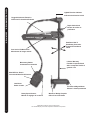
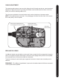
BowGuard 360°®
Breakaway Protection
Protection BowGuard
360°®
Mom/Off/Con Switch
Commande Mom./Arrêt/Continu
Heel Block
Butée du talon
Rugged Aluminum Extrusion
Extrusion En aluminium Robuste
Weedless Wedge Propeller
Hélice à bord anti-herbe
Permanent Magnet Motor
Moteur à aimant permanent
Momentary Switch
Commande momentanée
Rotary Speed Control
Molette de réglage de la vitesse
FEATURE INFORMATION DESCRIPTION
2
Specifications subject to change without notice.
Ces caractéristiques peuvent faire l’objet de modifications sans préavis.
Depth Collar Knob
Bouton du collier de
profondeur
Lighted Direction Indicator
Indicateur de direction éclairé
Lifetime Warranty
Flexible Composite Shaft
Arbre composite flexible à
garantie à vie
Gas Assist Lift Mechanism
Mécanisme de levage assisté

ASSEMBLY ASSEMBLAGE
3
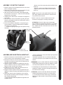
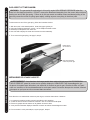
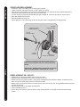
ASSEMBLY OF MOTOR TO MOUNT:
1. Place the mount on an elevated surface such as a work-
bench or tailgate of pickup.
2. Remove the 5/16” Allen screw and lock washer from the
mount using an Allen wrench. (See picture)
3. Align the key ways on the inside of the bowguard with
the ends links on the mount. Lower the motor assembly
straight down until seated.
4. Install the 5/16” Allen screw / lock washer and tighten to
10-12 ft/lbs.
5. Stow the motor into the flat position by pulling the rope/
handle to disengage the latch bar, allowing the motor to
fold into the flat position.
6. Once in the stowed or flat position, the gas spring pin
can be installed. Follow the steps below to install the
gas spring pin and spacers:
• Locate the upper gas spring pin and spacers in bag
assembly
• Align the end of the gas spring with the holes in the
outer arm
• Install pin, spacers and Phillips flat head screws
• Tighten screws until the heads are flush with the
outer arm
NOTE: Screws have a pre-applied thread locker, DO
NOT apply additional thread locker to screws as that
may prevent future removal.
7. Motor / mount can now be installed onto the boat.
Proceed to next page for mounting instructions.
ATTENTION: The 5/16” Allen screw must be tight
when installed and periodically tightened to 10-12 ft/lbs
(Step 4), which will allow the motor to be stowed prop-
erly. Tighten the Allen screw when the mount is in the
deployed position.
ASSEMBLAGE DU MOTEUR AU MONTANT :
1. Placez le montant sur une surface élevée, un banc de tra-
vail ou le hayon d’une camionnette par exemple.
2. Enlevez la vis Allen de 7,93 mm (5/16 po) et la rondelle
de sûreté du montant au moyen d’une clé Allen de 6,35
mm (⁄ po). (Voyez la photo.)
3. Alignez la rainure à l’intérieur du protège proue par rap-
port aux maillons en bout du montant. Abaissez l’assem-
blage du moteur tout droit pour l’asseoir.
4. Installez le 5/16” la vis d’Allen / la machine à laver de
serrure et serrez-vous à 10-12 ft/lbs.
5. Rangez le moteur à plat en tirant la poignée/corde pour
débrayer la barre de blocage, permettant ainsi de plier le
moteur.
6. Une fois le moteur à plat, la goupille du vérin pneuma-
tique peut être remontée. Suivez les étapes ci-dessous
pour installer cette goupille.
• Trouvez l’épingle printanière supérieure du gaz dans l’as-
semblage de sac.
• Alignez l’extrémité du vérin pneumatique par rapport aux
trous du bras externe.
• Remettez la goupille et la vis cruciforme à tête plate.
• Serrez la vis jusqu’à ce que sa tête soit au ras du bras
externe.
REMARQUE: Les vis ont été enduites de colle pour filetage,
N’APPLIQUEZ PAS plus de colle pour filetage sur les vis
car cela pourrait empêcher de les enlever à l’avenir.
7. L’assemblage de moteur/montant peut maintenant être
installé sur le bateau. Continuez à la page suivante pour
les instructions de montage.
ATTENTION: le 5/16” la vis d’Allen doit être serré quand
installé et périodiquement serré à 10-12 ft/lbs (le Pas
4), qui permettra au moteur d’être rangé correctement.
Serrez la vis d’Allen quand le mont est dans la position
déployée.
Allen Screw
Vis Allen
Safety Latch
Levier De Sécurité
keys
Clavettes

MONTAGE SUR LA PROUE :
Il est recommandé de se faire assister pour cette procédure.
1. Pour la pose, ne séparez pas l’arbre/moteur du garde-
proue Bowguard. Le ressort du garde-proue est sous
tension et doit toujours rester assuré.
2. 2. Posez le support, le moteur ramené à fond (à plat), sur
le pont du bateau :
• Montez le moteur le plus près possible de l’axe du
bateau.
• Assurez-vous qu’il n’y a pas d’obstacle au perçage dans
la zone de la proue située sous l’emplacement choisi.
• Assurez-vous que le support du moteur est assez loin
du bord du bateau. Le moteur ne doit rencontrer aucun
obstacle lorsqu’il est abaissé ou remonté.
3. 5. Montez la plaque sur la proue avec les boulons (1/4-20
x 8,89 cm (3-1/2 po)), rondelles et écrous fournis.
REMARQUE : Si possible, serrez tout les jeux de boulons
de montage, écrous et rondelles.
4. Installez la bande Velcro entre le moteur et le pont du
bateau, entre les deuxième et troisième jeux de trous de
montage.
5. Montez la plaque sur la proue par les trous percés au
moyen des boulons de 1/4-20 x 8,89 cm (3-1/2 po),
écrous et rondelles fournis.
REMARQUE: Si possible, fixez tous les jeux de boulons,
écrous et rondelles de montage.
6. Installez le stabilisateur de montant de proue (si compris).
Voyez la page 5 pour ses instructions d’installation.
CAUTION: MAKE SURE YOUR MOTOR IS MOUNTED ON A LEVEL
SURFACE
PRÉCAUTION : ASSUREZ-VOUS QUE LE MOTEUR EST MONTÉ SUR
UNE SURFACE DE NIVEAU.
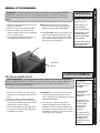
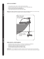
INSTALLATION OF THE BOWMOUNT:
We recommend that you have another person help with this
procedure.
1. For installation, do not remove the shaft/motor from the
Bowguard. The Bowguard spring is under tension and must
always remain secured.
2. Place the mount, with the motor in the fully retracted (flat)
position, on the deck of the boat:
• The motor should be mounted as close to the centerline
of the boat as possible.
• Make sure bow area under the chosen location is clear
and unobstructed for drilling.
• Make sure the motor rest is positioned far enough
beyond the edge of the boat. The motor, as it is lowered
into the water or raised into the boat, must not encounter
any obstructions.
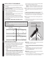
3. Once in position, determine which bolt pattern is to be
used (see below), mark at-least 4 of the holes in the bow
plate and drill through with a 9/32” drill bit. Either pattern
may be used when installing the motor.
Pattern 1. Minnkota 3” bolt pattern standard motors.
Pattern 2. Alternate 4” bolt pattern commonly used.
NOTE: If pattern 2 is to be used, the right side plate must
be removed to access the mounting holes in the bow
plate.
4. Install Velcro strap between the motor and deck of boat
between second and third set of mounting holes.
5. Mount the plate to the bow through the drilled holes using
the provided (1/4-20 x 3-1/2”) bolts, nuts and washers.
NOTE: If possible, secure all sets of mounting bolts, nuts
and washers.
6. Install the bow mount stabilizer (if included). See page 5
for installation instructions.
Velcro Strap
la bande Velcro
Position the Bowmount close to the
centerline of the boat and in an area
free of obstructions.
Positionnez le support de proue le
plus près possible de l’axe du bateau
et dans une zone sans obstacles.
INSTALLATION POSE
4

INSTALLATION POSE
5
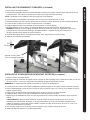
INSTALLING THE BOWMOUNT STABILIZER: (if Included)
1. Place motor in the stowed position
2. Unthread the composite rod from the bracket and attach bracket to the bottom of the bowguard using the 5/16” cap
screws and nuts. The nuts fit into pocket on the inside of the bowguard behind the spring.
NOTE: The bracket can be installed on the left or right side of the bowguard.
3. Pull the bumper off the stabilizer rod and place the rod next to the bracket as shown in photo.
4. Place the threaded end down onto the deck surface and mark the rod 3/4” above the top of the bracket (see photo)
5. Cut the rod to the mark and round the cut edge with a file or sandpaper.
6. Install the bottom bumper to the stabilizer rod and thread the rod into the bracket.
7.Adjust the stabilizer rod up or down to so that the tip just touches the support surface. See photo below.
WARNING: Adjusting the rod too tightly removes the end play needed for proper pin engagement and doing so
could prevent the mount from fully latching in the stowed position. If installed correctly, the rod tip should
lift off the deck about 1/4” without the mount unlatching.
8. Once adjusted, tighten the jam nut against the bracket, which will prevent the rod from turning.
9. Install top cap if threads are exposed.
INSTALLER LE STABILISATEUR DU MONTANT DE PROUE (si compris) :
1. Placez le moteur en position rangée.
2. Dévissez la tige de composite du support et fixez le support au bas du protège proue à l’aide des vis Allen de 7,93 mm
(5/16 po) et écrous. Les écrous entrent dans des cavités du protège proue derrière le ressort.
REMARQUE: Le support peut être installé sur la droite ou la gauche du protège proue.
3. Tirez le butoir pour l’enlever de la tige du stabilisateur et placez la tige près du support comme montré dans la photo.
4. Placez l’extrémité filetée vers le bas sur la surface du pont et marquez la tige à 19,1 mm (fl po) au-dessus du haut du
support (voyez la photo).
5. Coupez la tige au point marqué et arrondissez le bord coupé avec une lime ou de la toile émeri.
6. Installez le butoir inférieur sur la tige du stabilisateur et vissez la tige dans le support.
7. Réglez la tige de stabilisation de façon à ce que sa pointe touche à peine la surface de support. Voyez la photo ci-
dessus.
AVERTISSEMENT : Appuyer la tige fermement contre la surface de support pourrait éliminer le jeu en bout
nécessaire pour bien emboîter la goupille, ce qui pourrait empêcher le montant de s’emboîter complètement en
position de rangement. Quand elle est bien installée, la pointe de la tige devrait se lever de 6,35 à 12,7 mm (⁄ à fi
po) du pont sans décrocher le montant.
8. Une fois réglé, serrez l’écrou de blocage contre le support, ce qui empêchera la tige de tourner.
9. Installez le capuchon supérieur si les filets apparaissent.
3/4”
19.1mm
Optional mounting holes
Trous de montage optionnels

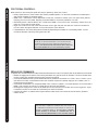
GAS ASSIST LIFT MECHANISM:
To disconnect one end of the gas spring, follow the instructions below:
1. With the mount in the stowed position, locate the upper cylinder pin.
2. Using two Phillips screwdrivers, remove 1 of the Phillips flat head screws.
3. Remove pin and spacers from outer arm.
4. Now it is safe to deploy the motor and remove the motor assembly.
5. To re-connect the gas spring, see page 3, step 6.
WARNING: The gas assist lift mechanism in this unit is under HIGH SPRING PRESSURE when the
motor is in the deployed position. DO NOT remove the BowGuard assembly from the mount without discon-
necting one end of the gas spring. Failure to do this can create a condition where accidental pulling of the
rope may cause the mount to spring open rapidly, striking anyone or anything in the direct path.
Phillips Screw
Vis cruciforme
Gas Spring Bracket
ressort au pas du gaz
MÉCANISME DE LEVAGE ASSISTÉ:
Pour décrocher une extrémité du ressort au pas du gaz, suivez les instructions ci-dessous :
1. Le montant en position rangée, trouvez la goupille du vérin supérieur.
2. À l’aide de deux tournevis cruciformes, enlevez 1 des vis cruciformes à tête plate.
3. Enlevez la goupille du bras externe en la glissant à travers le bras.
4. Vous pouvez maintenant déployer sûrement le moteur et enlevez l’assemblage de moteur.
5. Pour raccorder le vérin pneumatique, voyez la page 3, étape 6.
AVERTISSEMENT : Le mécanisme de levage assisté dans cette unité est sous HAUTE PRESSION
PAR LE RESSORT quand le moteur est en position déployée. N’ENLEVEZ PAS l’assemblage de gar-
de-proue du montant sans décrocher une extrémité du ressort au pas du gaz. Omettre de faire ceci peut
créer une condition où tirer accidentellement la corde peut causer l’ouverture brusque du montant, heurtant
quiconque ou quoi que se soit se trouvant dans sa course.
GAS ASSIST LIFT MECHANISM MÉCANISME DE LEVAGE ASSISTÉ
6

GAS ASSIST LIFT MECHANISM MÉCANISME DE LEVAGE ASSISTÉ
7
1. Disconnect one end of the gas spring. see
page 6 for instructions.
2. Place the motor in the deployed position.
3. Remove the 5/16” cap screw and lock
washer located on the top of the bowguard,
in front of the pull rope.
4. Lift motor/Bowguard assembly straight up
until bowguard is free from mount.
NOTE: Rope and latch bar should never
be pulled with the motor removed as the
assembly is under HIGH PRESSURE.
5. To re-assemble: Align the key ways on the
inside of the bowguard with the ends links
on the mount. Lower the assembly straight
down until seated Re-install the 5/16” cap
screw and washer and tighten.
WARNING
MOVING PARTS CAN
CRUSH OR CUT
•GAS ASSIST LIFT
MECHANISM IS
UNDER PRESSURE
•DISCONNECT GAS
SPRING BEFORE
REMOVING MOTOR
FROM MOUNT
•DO NOT PULL ROPE
UNTIL GAS SPRING IS
DISCONNECTED
Allen Screw
Vis Allen
WARNING: The gas assist lift mechanism in this unit is under HIGH SPRING
PRESSURE when the motor is in the deployed position. DO NOT remove the
BowGuard assembly from the mount without disconnecting one end of the gas
spring.
LES PIÈCES
MOBILES PEUVENT
ÉCRASSER OU
COUPER.
•LE MÉCANISME
DE LE VAGE
ASSISTÉ EST SOUS
PRESSION.
•DÉCROCHEZ LE
RESSORT AU PAS
DU GAZ AVANT
D’ENLEVER LE
MOTEUR DU
MONTANT.
•NE TIREZ PAS LA
CORDE SANS TOUT
D’ABORD AVOIR
DÉCROCHÉ LE
RESSORT AU PAS
DU GAZ.
DÉPOSE DU GARDE-PROUE :
AVERTISSEMENT : Le mécanisme de levage assisté dans cette unité est sous
HAUTE PRESSION PAR LE RESSORT quand le moteur est en position déployée.
N’ENLEVEZ PAS l’assemblage de garde-proue du montant sans décrocher une
extrémité du ressort au pas du gaz.
AVERTISSEMENT
REMOVAL OF THE BOWGUARD:REMOVAL OF THE BOWGUARD:
1. Décrochez un côté du vérin pneumatique.
Reportez-vous à la page 6 pour les instruc-
tions.
2. Placez le moteur en position déployée.
3. Enlevez la vis Allen de 7,93 mm (5/16 po)
et la rondelle de sûreté situées au haut du
protège proue, devant la corde.
4. Levez l’assemblage moteur/protège proue
tout droit jusqu’à ce que le protège proue
soit séparé du montant.
REMARQUE: La corde et la barre de blocage
ne devraient jamais être tirées quand le
moteur est enlevé car l’assemblage est sous
GRANDE PRESSION.
5. Pour remonter : Alignez la rainure à l’in-
térieur du protège proue par rapport aux
maillons en bout du montant. Abaissez l’as-
semblage du moteur tout droit pour l’asseoir.
Remettez la vis Allen de 7,93 mm (5/16 po)
et la rondelle, puis serrez-les.

OPERATION FONCTIONNEMENT
8
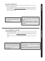
CAUTION: SWITCH THE MOM / OFF / CON CONTROL TO OFF WHEN
NOT IN USE. IF THE MOTOR CONTROL IS LEFT ON AND THE PRO-
PELLER ROTATION IS BLOCKED, SEVERE MOTOR DAMAGE CAN
RESULT. TROLLING MOTOR WILL DEPLETE BATTERY IF SWITCH IS
LEFT IN MOM (MOMENTARY) OR CON (CONTINUOUS) POSITION.
ATTENTION : METTEZ TOUJOURS LA COMMANDE MOM / OFF /
CON SUR ARR T LORSQUE LE MOTEUR N’EST PAS UTILISÉ. SI
LA COMMANDE DU MOTEUR EST SUR MARCHE ET L’HÉLICE EST
COINCÉE, LE MOTEUR RISQUE D’ TRE ENDOMMAGÉ. TROLLING
MOTEUR ÉPUISER LA BATTERIE SI L’INTERRUPTEUR EST À
GAUCHE DANS MOM (MOMENTANÉE) OU CON (CONTINU) POSITION.
FOOT PEDAL CONTROLS:
Most controls on the remote foot pedal are easy to operate by either foot or hand:
• Rotary Speed Control. These motors offer infinitely variable speeds. Turn the knob clockwise to increase speed
and counter-clockwise to decrease speed.
• MOM / OFF / CON Switch. When depressed to CON, the “constant on” allows you to run continuously without
keeping your foot on the pedal. Depress the switch MOM for momentary operation or to OFF.
• Momentary Switch. With the MON / OFF / CON set to “MOM”, a toe touch on the “momentary” switch turns the
motor on. Let up and the motor stops.
• Right /Left. Push the toe end of the foot rest down to turn right and push the heel end of the foot rest down to
turn left. Watch the lighted indicator on the motor head to check direction.
• Forward/Reverse. The motor always drives forward by depressing the constant on or momentary switch. You can
reverse the direction of thrust by turning the motor 180°.
PÉDALE DE COMMANDE :
La plupart des commandes peuvent être facilement effectuées à la main ou au pied à partir de la pédale de commande :
• Molette de réglage de la vitesse. Ces moteurs permettent une gamme infinie de vitesses. Tournez la molette dans
le sens horaire pour accélérer et dans le sens inverse pour ralentir.
• Commande MOM/OFF/CON (momentané/arrêt/continu). Mettez la commande sur « CON » pour « Continu » pour
faire tourner le moteur continuellement sans avoir à laisser le pied sur la pédale. Appuyez sur « MOM » pour un
fonctionnement momentané.
• Commande momentanée. La commande MON / OFF / CON sur « MOM », une simple pression sur la commande «
MOM » met le moteur en marche. Il s’arrête dès que la touche est relâchée.
• Droite/gauche. Appuyez sur l’avant de la pédale pour tourner à droite et sur le talon pour tourner à gauche. Voyez
l’indicateur lumineux sur le boîtier de commande pour vérifier la direction.
• Inverseur de marche. Le moteur tourne toujours dans le même sens. Pour inverser le sens de marche, pivotez le
moteur de 180°.

OPERATION FONCTIONNEMENT
9
BOW MOUNT OPERATION:
The bowmount is designed to fold back and lock the motor flat on the deck when not in use and to
provide secure stowage for transport.
• The pull rope releases the lock bar, which automatically engages when the unit is lowered or
raised into position. The pull grip and rope should be used to both lower and raise the unit.
• The motor rest positions the lower unit as it comes in contact with the nose of the mount and
guides it onto the motor rest.
WARNING : WHEN RAISING OR LOWER-
ING MOTOR, KEEP FINGERS CLEAR OF
ALL HINGE AND PIVOT POINTS AND ALL
MOVING PARTS.
FONCTIONNEMENT DU SUPPORT :
Le montage de proue est prévu pour se replier et pour verrouiller le moteur à plat sur le pont lorsqu’il
n’est pas utilisé et pour le transport.
• Le cordon libère la barre de verrouillage qui s’engage automatiquement lorsque le moteur est
abaissé ou relevé en position. Utilisez la poignée et le cordon pour abaisser et pour relever le
moteur.
• Le repos du moteur positionne le moteur lorsqu’il touche le nez du support et le guide dans le
repos.
ATTENTION : LORS DE L’ABAISSEMENT
OU DU RELEVAGE DU MOTEUR, VEILLEZ
À NE PAS METTRE LES DOIGTS PRÈS
DES POINTS DE PINCEMENT ET DES
PIÈCES MOBILES.
WARNING: WHEN INCLUDED WITH MOTOR,
THE VELCRO STRAP AND STABILIZER MUST
BE USED WHEN MOTOR IS IN THE STOWED
POSITION.
FAILURE TO INSTALL AND USE THESE SUP-
PLIED PARTS MAY RESULT IN DAMAGE TO
THE MOTOR NOT COVERED BY THE PRODUCT
WARRANTY.
AVERTISSMENT:QUAND COMPRIS AVEC LE MOTEUR,
LA BRIDE VELCRO ET LE STABILISATEUR DOIVENT
ÊTRE UTILISÉS QUAND LE MOTEUR EST EN POSITION
DE REMORQUAGE.
NE PAS INSTALLER ET UTILISER CES PIÈCES
FOURNIES PEUT ENTRAÎNER DES DÉGÂTS AU
MOTEUR N’ÉTANT PAS COUVERTS PAR LA GARANTIE.

ADJUSTMENTS REGLAGES
10
DEPTH ADJUSTMENT:
• Firmly grasp the outer shaft or control head and hold it steady.
• Loosen the depth setting knob on the depth collar until the shaft slides freely.
• Raise or lower the motor to the desired depth.
• Turn the motor control head to the desired position.
• Tighten depth setting knob to secure the motor in place.
NOTE: When setting the depth be sure the top of the motor is submerged at least 12” to avoid churning
or agitation of surface water. The propeller must be completely submerged.
RÉGLAGE DE LA PROFONDEUR :
• Saisissez fermement l’arbre extérieur ou le boîtier de commande et immobilisez-le.
• Desserrez le collier de serrage jusqu’à ce que l’arbre coulisse librement.
• Remontez ou abaissez le moteur à la profondeur voulue.
• Tournez le boîtier de commande sur la position voulue.
• Serrez le collier de serrage pour fixer le moteur en place.
REMARQUE : Lors du réglage de la profondeur, assurez-vous que le haut du moteur est immergé d’au
moins 30 cm (12 po) pour éviter tout remous à la surface de l’eau. L’hélice doit être entièrement immergée.
Depth Setting Knob
Bouton de réglage
de la profondeur
12” Minimum depth
Profondeur de 30 cm
minimum

ADJUSTMENTS REGLAGES
11
Cable Tension Adjustment Screw
Vis de réglage de la tension du câble
Cable Pulley
Poulie de câble
Stainless Steel Cable
Câble d’acier inoxydable
RÉGLAGE DU CÂBLE:
Le câble de direction est pré-réglé en usine mais l’usure normale doit être compensée de temps à
autre. Pour régler la longueur et la tension, tournez la vis de réglage située près du bas la pédale
de commande sous le couvercle du câble de commande.
Tournez la vis dans le sens horaire pour augmenter la tension et dans le sens contraire pour la
diminuer.
REMARQUE : Si le câble est trop détendu, il peut sortir du tambour dans le boîtier de commande
ou de la poulie dans la pédale.
CABLE ADJUSTMENT:
The steering cable tension is pre-set at the factory but will, through normal use, need occasional
adjustment. Adjust the tension by turning the Phillips screw located near the bottom of the foot
pedal, just under the steering cable cover.
Turn the screw clockwise to increase tension and counter-clockwise to decrease tension.
NOTE: If the cable becomes too loose, it may disengage for either the roller drum in the control
box or the pulley in the foot pedal.

CAUTIONS PRUDENCES
12
Attention:
•Avoid running your motor with the propeller out of the water. This may result in injuries from the rotating pro-
peller.
•It is recommended to set the speed selector to zero and place the motor in the deployed position prior to con-
necting power cables.
•Always ensure that the power cables are not twisted or kinked; and that they are securely routed to avoid a
safety or trip hazard. Ensure cables are unobstructed in all locations to avoid damaging the wire insulation.
Damage to the insulation could result in failure or injury.
•Always inspect the insulation of the power cables prior to use to ensure they are not damaged.
•Disregarding these safety precautions may result in an electrical short of the battery(s) and/or motor. Always
disconnect the motor from the battery(s) before cleaning or checking the propeller.
•Avoid submerging the complete motor as water may enter the lower unit through control head and shaft.
Water in the lower unit may cause an electrical short and damage the lower unit. This damage will not be
covered by warranty.
Caution!
•Always operate the motor in a safe distance away from obstructions. Never approach the motor when the
propeller is running. Contact with a spinning propeller may endanger you or others.
•Always exercise safe practices when using your motor; stay clear of other watercrafts, swimmers, and any
floating objects. Always obey water regulations applicable to your area of operation.
•Never operate the motor while under the influence of alcohol, drugs, medication, or other substances which
may impair your ability to safely operate equipment.
•This motor is not suitable for use in strong currents exceeding the thrust level of the motor.
The constant noise pressure level of the motor during use is less than 70dB(A). The overall vibration level does
not exceed 2,5m/sec≈.
Attention :
•Avoid la course à pied de votre moteur avec l’hélice à l’extérieur de l’eau. Cela peut s’ensuivre dans les bles-
sures de l’hélice tournante.
•Il est recommandé de montrer le sélectionneur de vitesse au zéro et placer le moteur dans la position
déployée avant de raccorder des câbles de batterie. Débranchez des câbles de batterie avant le fait de
ranger.
•Always garantissent que les câbles d’alimentation ne sont pas tournés ou kinked; et cela ils sont solidement
mis en déroute pour éviter le hasard de voyage ou une sécurité. Garantissez que les câbles sont libres dans
tous les endroits pour éviter de nuire à l’isolation métallique. Le dommage à l’isolation pourrait s’ensuivre
dans l’échec ou la blessure.
•Always inspectent l’isolation des câbles d’alimentation avant l’utilisation pour garantir qu’ils ne sont pas nuis.
•Disregarding ces précautions de sécurité peut s’ensuivre dans un électrique sauf de la batterie(s) et-ou le
moteur. Débranchez toujours le moteur de la batterie(s) avant le fait de nettoyer ou le fait de vérifier l’hélice.
•Évitez de submerger le moteur complet comme l’eau peut entrer dans l’unité plus basse par la tête de con-
trôle et le puits. L’eau dans l’unité plus basse peut provoquer un court électrique et nuire à l’unité plus
basse. Ce dommage ne sera pas couvert selon la garantie.
Prudence!
•Faites toujours marcher le moteur dans une distance sûre loin des obstructions. N’approchez-vous jamais du
moteur quand l’hélice court. Contact avec une hélice tournante peut mettre vous en danger ou d’autres.
•Exercez toujours des pratiques sûres en utilisant votre moteur; évitez d’autre watercrafts, les nageurs et n’im-
porte quels objets flottants. Obéissez toujours aux règlements d’eau applicables à votre région d’opération.
•Ne faites jamais marcher le moteur pendant que sous l’influence d’alcool, médicaments, médication, ou d’au-
tres substances qui peuvent diminuer votre capacité de bien faire marcher l’équipement.
•Ce moteur n’est pas convenable pour l’utilisation dans de forts courants excédant le niveau de poussée du
moteur.
Le niveau de pression bruyant constant du moteur pendant l’utilisation est moins de 70 décibels (A). Le niveau
de vibration général n’excède pas 2,5m/sec ≈.

BATTERY INFORMATION INFORMATIONS DE BATTERIE
13
BATTERY INFORMATION:
The motor will operate with any deep cycle marine 12 volt battery (two 12 volt batteries wired in series for 24
volt motors or three 12 volt batteries wire in series for 36 volt motors). For best results use a deep cycle,
marine battery with at least a 115 ampere hour rating. Maintain batteries at full charge. Proper care will
ensure having battery power when you need it and will significantly improve the battery life. Failure to
recharge lead-acid batteries (within 12-24 hours) is the leading cause of premature battery failure. Use a
variable rate Minn Kota charger to avoid overcharging.
If you are using a battery to start a gasoline outboard, we recommend that you use a separate deep cycle
marine battery/batteries for your Minn Kota trolling motor.
Advice regarding batteries:
Never connect the (+) and the (–) terminals of the battery together. Take care that no metal object can
fall onto the battery and short the terminals. This would immediately lead to a short and utmost fire
danger.
INFORMATIONS DE BATTERIE :
Ces moteur feront marcher avec n’importe quel fusilier marin de cycle profond la batterie de 12 volts (deux 12
volts batteries télégraphié en série pour les moteurs de 24 volts ou trois 12 volts batteries le fil en série pour
les moteurs de 36 volts). Car les meilleurs résultats utilisent un cycle profond, la batterie marine avec au
moins une 115 heure d’ampère en évaluant. Maintenez batteries à la charge complète. Le soin nécessaire
garantira le pouvoir de batterie ayant quand vous en avez besoin et améliorerez de façon significative la
vie de batterie. L’échec de recharger le premier acide batteries (au cours de 12-24 heures) est la principale
cause d’échec de batterie prématuré. Utilisez un taux variable Minn Kota le chargeur pour éviter de faire
payer au prix fort.
Si vous utilisez une batterie pour commencer un moteur hors-bord d’essence, nous recommandons que vous
utilisez un fusilier marin de cycle profond séparé battery/batteries de votre Minn Kota le moteur.
Conseil quant à batteries :
Ne communiquez jamais le (+) et (-) les terminus de la batterie ensemble. Faites attention qu’aucun
objet en métal ne puisse tomber sur la batterie et court les terminus. Cela causerait immédiatement
un danger de feu court et suprême.

BATTERY CONNECTION BRANCHEMENT DE LA BATTERIE
14
WARNING: • BEFORE CONNECTING BATTERY, MAKE
SURE THE MOM/CON SWITCH IS IN THE OFF POSI-
TION.
• IMPROPER WIRING OF 24 OR 36 VOLT SYSTEMS
COULD CAUSE BATTERY EXPLOSION!
• KEEP LEADWIRE WING NUT CONNECTION TIGHT
AND SOLID TO BATTERY TERMINALS.
• LOCATE BATTERY IN A VENTILATED COMPART-
MENT.
AVERTISSEMENT : • AVANT DE RACCORDER LA
BATTERIE, VÉRIFIEZ QUE LA COMMANDE MOM/
OFF/CON EST SUR ARRÊT.
• UNE ERREUR DE POLARITÉ DANS UN CIRCUIT
DE 24 V PEUT PROVOQUER L’EXPLOSION DE LA
BATTERIE !
• VEILLEZ À CE QUE LES ÉCROUS PAPILLONS
SUR LES BORNES DE LA BATTERIE SOIENT BIEN
SERRÉS.
• PLACEZ LA BATTERIE DANS UN COMPARTIMENT
AÉRÉ.
BATTERY CONNECTION:
24 Volt Systems: FORTREX 80
1. Make sure that the motor is switched off (speed selector on
“0”).
2. Two 12 volt batteries are required.
3. The batteries must be wired in series, only as directed in wir-
ing diagram, to provide 24 volts.
a. Connect a connector cable to positive ( + ) terminal of bat-
tery 1 and to negative ( – ) terminal of battery 2.
b. Connect positive (+) red lead to positive (+) terminal on
battery 2.
c. Connect negative (–) black lead to negative (–) terminal of
battery 1.
4. For safety reasons do not switch the motor on until the propel-
ler is in the water.
36 Volt Systems FORTREX 101 / 112
1. Make sure that the motor is switched off (speed selector on “0”).
2. Three 12 volt batteries are required.
3. The batteries must be wired in series, only as directed in wiring
diagram, to provide 36 volts.
a. Connect a connector cable to positive ( + ) terminal of battery
1 and to negative ( – ) terminal of battery 2.
b. Connect a connector cable to positive (+) terminal of battery
2 and to negative (–) terminal of battery 3.
c. Connect positive (+) red lead to positive (+) terminal on bat-
tery 3.
d. Connect negative (–) black lead to negative (–) terminal of
battery 1.
4. For safety reasons do not switch the motor on until
the propeller is in the water.
Note: Do not use your crank battery as one of the
two or three supply batteries; crank batteries are
not built for deep discharge service.
RACCORDEMENT DE LA BATTERIE :
Systèmes de 24 V FORTREX 80
1. Assurer que le moteur est éteint (le sélectionneur de vitesse sur
“0”).
2. Deux 12 volts batteries sont exigés.
3. Le batteries doit être télégraphié en série, seulement comme
dirigé dans le schéma de connexions, fournir 24 volts.
a. Raccordez un câble de connecteur à positif (+) le terminus de
batterie 1 et à négatif (-) le terminus de batterie 2.
b. Communiquez positif (+) l’avance rouge à positif (+) le termi-
nus sur la batterie 2.
c. Communiquez négatif (–) le graphite pour enduit à négatif (–)
le terminus de batterie 1.
4. Pour la sécurité les raisons n’allument pas le moteur avant que
l’hélice ne soit dans l’eau.
Système de 36 V FORTREX 101 / 112
1. Assurer que le moteur est éteint (le sélectionneur de vitesse sur
“0”).
2. Trois 12 volts batteries êtes exigés.
3. Le batteries doit être télégraphié en série, seulement comme dirigé
dans le schéma de connexions, fournir 36 volts.
a. Raccordez un câble de connecteur à positif (+) le terminus de
batterie 1 et à négatif (-) le terminus de batterie 2.
b. Raccordez un câble de connecteur à positif (–) le terminus de
batterie 2 et à négatif (–) le terminus de batterie 3.
c. Communiquez positif (+) l’avance rouge à positif (+) le terminus
sur la batterie 3.
d. Communiquer négatif (–) le graphite pour enduit à négatif (–) le
terminus de batterie 1.
4. Pour la sécurité les raisons n’allument pas le moteur jusqu’à ce
que l’hélice soit dans l’eau.
En installant une prise de courant sur le
leadwire, observez la polarité nécessaire et
suivez des instructions dans votre manuel de
propriétaire de bateau.
Voir le schéma de connexions sur les pages
suivantes.

WIRING DIAGRAM SCHÉMA DE CÂBLAGE
15
12v
24v
36v
B+
M-
B-
M+
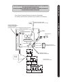
BLK/RED, NOIR/ROUGE M+
BLACK/NOIR M-
CONTROL BOARD/
CARTE DE COMMANDE
INDICATOR LIGHT
VOYANT
BLACK/NOIR B-
RED/ROUGE B+
MOTOR/
MOTEUR
MOMENTARY SWITCH
COMMANDE MOMENTANEE
SPEED ADJUSTMENT KNOB
MOLETTE DE REGLAGE DE LA VITESSE
BATTERY 1
BATTERIE 1
BATTERY 2
BATTERIE 2
BATTERY 3
BATTERIE 3
BATTERY 1
BATTERIE 1
BATTERY 2
BATTERIE 2
BATTERY 1
BATTERIE 1
YELLOW / JAUNE
GREEN / VERT
WHITE / BLANC
BLK/BROWN
NOIR/MARRON
BLK/ORANGE
NOIR/ORANGE
OPTIONAL BROWN WIRE *
SEE BOAT WIRING DIAGRAM
FIL MARRON OPTIONNEL *
ÉQUIPÉS DE SONAR. VOYEZ LE SCHÉMA DE CÂBLAGE DU BATEAU.
MOM/OFF/CON SWITCH
COMMANDE MOM/OFF/CON
RED/ROUGE M+
BLACK/NOIR M-
FUSE *
FUSIBLE *
* US MOTORS ONLY
* MOTEURS US SEULEMENT
THIS IS A UNIVERSAL MULTI-VOLTAGE DIAGRAM. DOUBLE CHECK YOUR MOTORS
VOLTAGE FOR PROPER CONNECTIONS
CECI EST UN SCHÉMA À TENSION MULTIPLE UNIVERSEL. REVÉRIFIEZ LA TENSION DE
VOTRE MOTEUR POUR BIEN LE BRANCHER.
Over-Current Protection Devices not shown in illustrations.
Les Artifices de Protection Suractuels non montrés en illustrations.

BOAT RIGGING AND PRODUCT INSTALLATION:
For safety and compliance reasons, we recommend that you follow American Boat and Yacht Council (ABYC)
standards when rigging your boat. Altering boat wiring should be completed by a qualifi ed marine technician. The
following specifi cations are for general guidelines only:
CAUTION: These guidelines apply to general rigging to support your Minn Kota motor. Powering multiple motors
or additional electrical devices from the same power circuit may impact the recommended conductor gauge and
circuit breaker size. If you are using wire longer than that provided with your unit, follow the conductor gauge
and circuit breaker sizing table below. If your wire extension length is more than 25 feet we recommend that you
contact a qualifi ed marine technician.
An over-current protection device (circuit breaker or fuse) must be used. Coast Guard requirements dictate
that each ungrounded current-carrying conductor must be protected by a manually reset, trip-free circuit breaker
or fuse. The type (voltage and current rating) of the fuse or circuit breaker must be sized accordingly to the troll-
ing motor used. The table below gives recommended guidelines for the circuit breaker sizing.
Reference:
United States Code of Federal Regulations: 33 CFR 183 - Boats and Associated Equipment
ABYC E-11: AC and DC Electrical Systems on Boats.
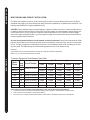
*Conductor Gauge and Circuit Breaker Sizing Table
Motor
Thrust
Max
Amp
Draw
Circuit Breaker
Wire Extension Length
5 feet 10 feet 15 feet 20 feet 25 feet
30# 30 50 Amp @ 12 VDC 10 AWG 10 AWG 8 AWG 6 AWG 4 AWG
40#, 45# 42 10 AWG 8 AWG 6 AWG 4 AWG 4 AWG
50#, 55# 50 60 Amp @ 12 VDC 8 AWG 6 AWG 4 AWG 4 AWG 2 AWG
70# 42 50 Amp @ 24 VDC 10 AWG 10 AWG 8 AWG 8 AWG 6 AWG
80# 56 60 Amp @ 24 VDC 8 AWG 8 AWG 8 AWG 6 AWG 6 AWG
101# 46 50 Amp @ 36 VDC 8 AWG 8 AWG 8 AWG 8 AWG 8 AWG
112# 52 60 Amp @ 36 VDC 8 AWG 8 AWG 8 AWG 8 AWG 8 AWG
E-Drive 40 50 Amp @ 48 VDC 10 AWG 10 AWG 10 AWG 10 AWG 10 AWG
*The conductor and circuit breaker sizing table above is only valid for the following assumptions.
1. No more than three (3) conductors are bundled together inside a sheath or conduit outside of engine spaces.
2. Each conductor has 105 degree C temp rated insulation.
3. No more than 5% voltage drop allowed at full motor power based on published product power requirements.
"BATEAU GRÉEMENT ET PRODUIT DE L'INSTALLATION :"
"Pour des raisons de sécurité et de conformité, nous recommandons de suivre les normes de l’American"
"Boat And Yacht Council (ABYC) lorsque truquer votre bateau. Modifi er le câblage du bateau doit être complété
par un technicien marin qualifi é. Les spécifi cations suivantes sont uniquement des directives générales :"
"Avertissement : Ces directives s'appliquent au gréement générale à l'appui de votre moteur Minn Kota."
"Alimenter plusieurs moteurs ou des dispositifs électriques supplémentaires depuis le même circuit de puissance
peut infl uencer la taille recommandée de la jauge du conducteur et disjoncteur. Si vous utilisez fi l plus long que
celui fourni avec votre unité, suivre le conducteur jauge et le disjoncteur dimensionnement tableau ci-dessous.
Si votre fi l longueur d’extension est plus de 7.5 metres nous recommandons que vous contacter un technicien
marin qualifi é."
"Un dispositif de protection de surintensité (disjoncteur ou fusible) doit être utilisé. Les exigences de"
"la Garde-Côte américain disent que chaque conducteur sans fondement de porteurs de courant doit être
protégé par un disjoncteur mise en circuit, à déclenchement libre ou un fusible. Le type (tension et courant nom-
inal) du fusible ou disjoncteur doit être dimensionné en conséquence pour le moteur utilisé. Le tableau ci-des-
sous donne les directives pour le calibrage de disjoncteur."
“Référence :”
“United States Code of Federal Regulations : CFR 33 183 – bateaux et équipement connexe”
“ABYC E-11: AC et DC des systèmes électriques à bord de bateaux”
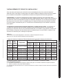
"* Jauge de conducteur et disjoncteur Table de dimensionnement Longueur totale de chef d'orchestre “
Moteur
poussée
Max
Ampère Disjoncteur
Fil Longueur d'extension
1.5
mètres
3
mètres
4.5
mètres
6
mètres
7.5
mètres
30# 30 50 Amp @ 12 VDC 5 mm 5 mm 8 mm 13 mm 21 mm
40#, 45# 42 5 mm 8 mm 13 mm 21 mm 21 mm
50#, 55# 50 60 Amp @ 12 VDC 8 mm 13 mm 21 mm 21 mm 33 mm
70# 42 50 Amp @ 24 VDC 5 mm 5 mm 8 mm 8 mm 13 mm
80# 56 60 Amp @ 24 VDC 8 mm 8 mm 8 mm 13 mm 13 mm
101# 46 50 Amp @ 36 VDC 8 mm 8 mm 8 mm 8 mm 8 mm
112# 52 60 Amp @ 36 VDC 8 mm 8 mm 8 mm 8 mm 8 mm
E-Drive 40 50 Amp @ 48 VDC 5 mm 5 mm 5 mm 5 mm 5 mm
"* Le disjoncteur tableau ci-dessus de dimensionnement et chef d'orchestre est uniquement valable"
"pour les hypothèses suivantes."
"1. Pas plus de 3 conducteurs sont regroupés à l'intérieur d'une gaine ou conduites à l'extérieur des espaces de moteur."
"2. Chaque conducteur a 105oc temp, évalué à isolation."
"3. Pas plus d'une chute de tension de 5 % a permis à la puissance du moteur complet en fonction des besoins de puissance
produit publié."
CIRCUIT BREAKER DISJONCTEUR
16

BOAT RIGGING AND PRODUCT INSTALLATION:
For safety and compliance reasons, we recommend that you follow American Boat and Yacht Council (ABYC)
standards when rigging your boat. Altering boat wiring should be completed by a qualifi ed marine technician. The
following specifi cations are for general guidelines only:
CAUTION: These guidelines apply to general rigging to support your Minn Kota motor. Powering multiple motors
or additional electrical devices from the same power circuit may impact the recommended conductor gauge and
circuit breaker size. If you are using wire longer than that provided with your unit, follow the conductor gauge
and circuit breaker sizing table below. If your wire extension length is more than 25 feet we recommend that you
contact a qualifi ed marine technician.
An over-current protection device (circuit breaker or fuse) must be used. Coast Guard requirements dictate
that each ungrounded current-carrying conductor must be protected by a manually reset, trip-free circuit breaker
or fuse. The type (voltage and current rating) of the fuse or circuit breaker must be sized accordingly to the troll-
ing motor used. The table below gives recommended guidelines for the circuit breaker sizing.
Reference:
United States Code of Federal Regulations: 33 CFR 183 - Boats and Associated Equipment
ABYC E-11: AC and DC Electrical Systems on Boats.
*Conductor Gauge and Circuit Breaker Sizing Table
Motor
Thrust
Max
Amp
Draw
Circuit Breaker
Wire Extension Length
5 feet 10 feet 15 feet 20 feet 25 feet
30# 30 50 Amp @ 12 VDC 10 AWG 10 AWG 8 AWG 6 AWG 4 AWG
40#, 45# 42 10 AWG 8 AWG 6 AWG 4 AWG 4 AWG
50#, 55# 50 60 Amp @ 12 VDC 8 AWG 6 AWG 4 AWG 4 AWG 2 AWG
70# 42 50 Amp @ 24 VDC 10 AWG 10 AWG 8 AWG 8 AWG 6 AWG
80# 56 60 Amp @ 24 VDC 8 AWG 8 AWG 8 AWG 6 AWG 6 AWG
101# 46 50 Amp @ 36 VDC 8 AWG 8 AWG 8 AWG 8 AWG 8 AWG
112# 52 60 Amp @ 36 VDC 8 AWG 8 AWG 8 AWG 8 AWG 8 AWG
E-Drive 40 50 Amp @ 48 VDC 10 AWG 10 AWG 10 AWG 10 AWG 10 AWG
*The conductor and circuit breaker sizing table above is only valid for the following assumptions.
1. No more than three (3) conductors are bundled together inside a sheath or conduit outside of engine spaces.
2. Each conductor has 105 degree C temp rated insulation.
3. No more than 5% voltage drop allowed at full motor power based on published product power requirements.
"BATEAU GRÉEMENT ET PRODUIT DE L'INSTALLATION :"
"Pour des raisons de sécurité et de conformité, nous recommandons de suivre les normes de l’American"
"Boat And Yacht Council (ABYC) lorsque truquer votre bateau. Modifi er le câblage du bateau doit être complété
par un technicien marin qualifi é. Les spécifi cations suivantes sont uniquement des directives générales :"
"Avertissement : Ces directives s'appliquent au gréement générale à l'appui de votre moteur Minn Kota."
"Alimenter plusieurs moteurs ou des dispositifs électriques supplémentaires depuis le même circuit de puissance
peut infl uencer la taille recommandée de la jauge du conducteur et disjoncteur. Si vous utilisez fi l plus long que
celui fourni avec votre unité, suivre le conducteur jauge et le disjoncteur dimensionnement tableau ci-dessous.
Si votre fi l longueur d’extension est plus de 7.5 metres nous recommandons que vous contacter un technicien
marin qualifi é."
"Un dispositif de protection de surintensité (disjoncteur ou fusible) doit être utilisé. Les exigences de"
"la Garde-Côte américain disent que chaque conducteur sans fondement de porteurs de courant doit être
protégé par un disjoncteur mise en circuit, à déclenchement libre ou un fusible. Le type (tension et courant nom-
inal) du fusible ou disjoncteur doit être dimensionné en conséquence pour le moteur utilisé. Le tableau ci-des-
sous donne les directives pour le calibrage de disjoncteur."
“Référence :”
“United States Code of Federal Regulations : CFR 33 183 – bateaux et équipement connexe”
“ABYC E-11: AC et DC des systèmes électriques à bord de bateaux”
"* Jauge de conducteur et disjoncteur Table de dimensionnement Longueur totale de chef d'orchestre “
Moteur
poussée
Max
Ampère Disjoncteur
Fil Longueur d'extension
1.5
mètres
3
mètres
4.5
mètres
6
mètres
7.5
mètres
30# 30 50 Amp @ 12 VDC 5 mm 5 mm 8 mm 13 mm 21 mm
40#, 45# 42 5 mm 8 mm 13 mm 21 mm 21 mm
50#, 55# 50 60 Amp @ 12 VDC 8 mm 13 mm 21 mm 21 mm 33 mm
70# 42 50 Amp @ 24 VDC 5 mm 5 mm 8 mm 8 mm 13 mm
80# 56 60 Amp @ 24 VDC 8 mm 8 mm 8 mm 13 mm 13 mm
101# 46 50 Amp @ 36 VDC 8 mm 8 mm 8 mm 8 mm 8 mm
112# 52 60 Amp @ 36 VDC 8 mm 8 mm 8 mm 8 mm 8 mm
E-Drive 40 50 Amp @ 48 VDC 5 mm 5 mm 5 mm 5 mm 5 mm
"* Le disjoncteur tableau ci-dessus de dimensionnement et chef d'orchestre est uniquement valable"
"pour les hypothèses suivantes."
"1. Pas plus de 3 conducteurs sont regroupés à l'intérieur d'une gaine ou conduites à l'extérieur des espaces de moteur."
"2. Chaque conducteur a 105oc temp, évalué à isolation."
"3. Pas plus d'une chute de tension de 5 % a permis à la puissance du moteur complet en fonction des besoins de puissance
produit publié."
CIRCUIT BREAKER DISJONCTEUR
17

PROPELLER HÉLICE
18
Prop nut
Écrou de l’hélice
Washer
Rondelle Drive pin
Goupille d’entraînement
Weedless Propeller
Hélice anti-herbe
PROPELLER REPLACEMENT:
• Disconnect motor from battery prior to changing the propeller.
• Hold the propeller and loosen the prop nut with a pliers or a wrench.
• Remove prop nut and washer. If the drive pin is sheared/broken, you will need to hold the shaft steady with a
screwdriver blade pressed into the slot on the end of the shaft.
• Turn the old prop to horizontal (as illustrated) and pull it straight off. If the drive pin falls out, push it back in.
• Align new propeller with drive pin.
• Install prop washer and prop nut.
• Tighten prop nut 1/4 turn past snug. [25-35 inch lbs.] Be careful, over tightening can damage prop.
REMPLACEMENT DE L’HÉLICE :
• Débranchez le moteur de la batterie avant de changer l’hélice.
• Saisissez l’hélice et desserrez l’écrou avec une pince ou une clé.
• Retirez l’écrou et la rondelle de l’hélice. Si la goupille d’entraînement est cassée ou cisaillée, immobilisez l’arbre
avec un tournevis pressé dans la fente à l’extrémité de l’arbre.
• Mettez l’hélice à l’horizontale (schéma ci-contre) et tirez l’hélice droit sur son axe. Si la goupille d’entraînement sort,
remettez-la en place.
• Alignez l’hélice neuve sur la goupille d’entraînement.
• Posez la rondelle et l’écrou.
• Serrez l’écrou de 1/4 de tour après contact [3-4 Nm]. Faites attention, un serrage excessif peut endommager
l’hélice.
CAUTION: DISCONNECT THE MOTOR FROM THE BAT-
TERY BEFORE BEGINNING ANY PROP WORK OR MAINTE-
NANCE.
PRÉCAUTION : DÉBRANCHEZ LE MOTEUR DE LA BATTERIE
AVANT D’ENTREPRENDRE L’ENTRETIEN DE L’HÉLICE.
Slot End
Extrémité fendue

MAXIMIZER™: Les circuits électroniques incorporés
du Maximizer créent des impulsions modulées pour pro-
longer le temps de fonctionnement et la vie de la batterie.
Au moyen de la commande de vitesse du Maximizer, vous
pouvez, dans quelques cas, expérimenter des interférenc-
es sur l’affichage de votre détecteur de profondeur. Nous
conseillons l’emploi d’une batterie marine à cycles variables
séparée pour votre moteur de pêche à la traîne et d’aliment-
er le détecteur de profondeur avec la batterie de démarrage.
Si les problèmes persistent toujours, appelez notre service
au client au 1-800-227-6433.
MAXIMIZER™: The built-In Maximizer’s electronics
create pulse width modulation to provide longer running
time and extended battery life. With the Maximizer speed
control, you may, in some applications, experience interfer-
ence in your depth finder display. We recommend that you
use a separate deep cycle marine battery for your trolling
motor and that you power the depth finder from the starting
/ cranking battery. If problems still persist, call our service
department at 1-800-227-6433.
MAINTENANCE:
1. After use, these units should be rinsed with fresh water, then wiped down with a cloth dampened with an aqueous based sili-
cone spray such as Armor All®. This series of motors is not equipped for salt water exposure.
2. The propeller must be cleaned of weeds and fishing line. The line can get behind the prop, damage the seals and allow water to
enter the motor. Check this after every 20 hours of operation.
3. Before each use, check to see that the prop nut is secure.
4. To prevent accidental damage during trailering or storage, disconnect the battery whenever the motor is off of the water. For
prolonged storage, lightly coat all metal parts with an aqueous based silicone spray.
5. For maximum performance, restore battery to full charge before each use.
6. Keep battery terminals clean with fine sandpaper or emery cloth.
7. The weedless wedge propeller is designed to provide absolute weed free operation with very high efficiency. To maintain this top
performance, the leading edge of the blades must be kept smooth. If they are rough or nicked from use, restore to smooth by sand-
ing with fine sandpaper.
8. Grease latch pins periodically to prevent binding or sticking.
9. The 5/16” Allen screw that attaches the motor to the mount should be periodically tightened to 10-12 ft/lbs to prevent motor stowing
problems. Tighten the Allen screw when the mount is in the deployed position.
ENTRETIEN :
1. Après chaque utilisation, rincez le moteur à l’eau douce puis essuyez-le avec un chiffon imprégné de silicone tel que
l’Armorall®. Les moteurs de cette série ne sont pas prévus pour fonctionner dans l’eau de mer.
2. Nettoyez l’hélice et débarrassez-la des herbes et des fils de pêche. Les fils peuvent passer derrière l’hélice, user les joints et
laisser l’eau pénétrer dans le moteur. Effectuez cette inspection toutes les 20 heures d’utilisation.
3. Avant chaque utilisation, assurez-vous que l’écrou de l’hélice est bien serré.
4. Pour un remisage prolongé, débranchez la batterie et enduisez toutes les parties métalliques d’une fine couche de silicone
pulvérisée.
5. Pour des performances maximales, rechargez la batterie à fond avant chaque utilisation.
6. Veillez à la propreté des bornes de la batterie, nettoyez-les avec du papier de verre fin ou de la toile émeri.
7. L’hélice à bord anti-herbe est prévue pour assurer un fonctionnement sans enroulement d’herbe et une grande efficacité. Maintenez
le bord d’attaque des pales lisse pour maintenir ces performances optimales. Si le bord d’attaque est émoussé, poncez-le avec du
papier de verre fin.
8. Le loquet de graisse épingle périodiquement pour prévenir le fait d’attacher ou collant.
9. Le 5/16” la vis d’Allen qui attache le moteur au mont devrait être périodiquement serré à 10-12 ft/lbs pour prévenir des
problèmes rangeants automobiles. Serrez la vis d’Allen quand le mont est dans la position déployée.
MAXIMIZER MAXIMIZER MAINTENANCE ENTRETIEN
19

TROUBLESHOOTING DÉPANNAGE
20
TROUBLESHOOTING:
1. Motor fails to run or lacks power:
• Check battery connections for proper polarity.
• Make sure terminals are clean and corrosion free. Use
fine sandpaper or emery cloth to clean terminals.
• Check battery water level. Add water if needed.
2. Motor loses power after a short running time:
• Check battery charge, if low, restore to full charge.
3. Motor is difficult to steer:
• Check steering cables for proper tension. Adjust as nec-
essary.
4. You experience prop vibration during normal operation:
• Remove and rotate the prop 180°. See removal instruc-
tions in prop section.
5. Unit difficult to deploy:
• Lubricate the latch pins. Stow and deploy motor a few
times until latch pins latch freely.
6. Motor drains battery when not in use.
Motors equipped with a Maximizer control board, will draw
a small amount of current when connected to the battery,
this is normal. To prevent battery drain, disconnect power
to the motor when the boat is not in use.
7. Lift-assist not functioning:
• Ensure lift-assist pin was installed prior to motor use.
8. Motor shaft falls to one side of the motor shaft yoke when
stowing.
• The 5/16” Allen screw that attaches the motor to the
mount should be periodically tightened to 10-12 ft/lbs.
Tighten the Allen screw when the mount is in the deployed
position.
NOTE: For all other malfunctions, see enclosed authorized
service center listing for nearest service center.
DÉPANNAGE :
1. Le moteur ne tourne pas ou manque de puissance :
• Vérifiez la polarité du raccordement à la batterie.
• Assurez-vous que les bornes de la batterie sont propres
et ne sont pas corrodées. Nettoyez-les avec du papier de
verre fin ou de la toile émeri.
• Vérifiez le niveau d’eau de la batterie. Ajoutez-en s’il le
faut.
2. Le moteur perd de sa puissance après un court moment de
fonctionnement :
• Vérifiez la charge de la batterie et rechargez-la si elle est
basse.
3. Le moteur est difficile à diriger :
• Vérifiez la tension du câble de direction. Réglez-la s’il le
faut.
4. Des vibrations se font sentir lors du fonctionnement normal
de l’hélice :
• Déposez l’hélice et tournez-la de 180°. Voyez les
instructions de dépose dans la section sur l’hélice.
5. Unité difficile à déployer :
• Le ressort au pas du gaz se détent après de longues
périodes au repos. Rangez et déployez le moteur plusieurs
fois jusqu’à ce que les goupilles de verrouillage s’engagent
librement.
6. Trolling moteur draine la batterie lorsqu’elle n’est pas
utilisée.
Switch MOM / OFF / CON passer sur pied pour position
OFF lorsqu’il n’est pas utilisé. Trolling moteur épuiser
la batterie si l’interrupteur est à gauche dans MOM
(momentanée) ou CON (continu) position.
7. Printemps du gaz non fonctionnement:
•Garantissez que l’épingle printanière du gaz a été installée
avant l’utilisation
8. Le puits automobile tombe à un côté du joug de puits
automobile en rangeant.
• le 5/16” la vis d’Allen qui attache le moteur au mont devrait
être périodiquement serrée à 10-12 ft/lbs. Serrez la vis
d’Allen quand le mont est dans la position déployée.
REMARQUE : Pour tout autre dysfonctionnement, voyez la
liste ci-jointe pour trouver le centre de service après-vente
agréé le plus proche.
La page est en cours de chargement...
La page est en cours de chargement...
La page est en cours de chargement...
La page est en cours de chargement...
La page est en cours de chargement...
La page est en cours de chargement...
La page est en cours de chargement...
La page est en cours de chargement...
-
 1
1
-
 2
2
-
 3
3
-
 4
4
-
 5
5
-
 6
6
-
 7
7
-
 8
8
-
 9
9
-
 10
10
-
 11
11
-
 12
12
-
 13
13
-
 14
14
-
 15
15
-
 16
16
-
 17
17
-
 18
18
-
 19
19
-
 20
20
-
 21
21
-
 22
22
-
 23
23
-
 24
24
-
 25
25
-
 26
26
-
 27
27
-
 28
28


MINN KOTA FORTREX Manuel utilisateur
- Taper
- Manuel utilisateur
- Ce manuel convient également à
dans d''autres langues
- English: MINN KOTA FORTREX User manual
Documents connexes
-
MINN KOTA Riptide Manuel utilisateur
-
MINN KOTA POWERDRIVE V2 Manuel utilisateur
-
MINN KOTA PowerDrive Master User Manual
-
-
MINN KOTA 2377123 Le manuel du propriétaire
-
-
-
-
-
