Maxtor 777 W V1.0 Manuel utilisateur
- Catégorie
- Des caméras de sécurité
- Taper
- Manuel utilisateur
Ce manuel convient également à

Digital Multiplex Recorder
USER’S MANUAL
777 W V1.0
Please read the instructions thoroughly before operation and retain it for future reference.

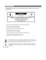
The lightning flash with arrowhead symbol, within an equilateraltriangle, is intended to alert
the user to the presence ofuninsulated"dangerous voltage" within the product's enclosure that
may be of sufficient magnitude to constitute a risk of electric shock to persons.
The exclamation point within an equilateral triangle is intendedto alert the user to the presence
of important operating and maintenance-(servicing) instructions in the literature accompanying
the appliance.
All the safety and operating instructions should be read before operation. The improper operation may cause
permanent damage.
• Please use the provided adaptor (Other adaptor is not suitable for this machine).
• Please lift and place this equipment gently.
• Do not expose this equipment to open sunlight.
• Do not use this equipment near water or in contact with water.
• Do not spill liquid of any kind on the equipment.
• Please power down the unit before unplugging.
• Do not switch the Power On & Off within short period of time (within 3 seconds).
• Do not attempt to have this equipment serviced by yourself.
• Installation should be made by qualified service personnel.
WARNING

What Do You Get
What Do You Get
?
?
• FEATURES--------------------------------------------------------------------------------------
• PACKAGE INCLUDING ----------------------------------------------------------------------
Before Operation
Before Operation
• INSTALLATION GUIDE----------------------------------------------------------------------
• FRONT PANEL ----------------------------------------------------------------------------------
• BACK PANEL-----------------------------------------------------------------------------------
Basic Operation
Basic Operation
• START THIS UNIT ------------------------------------------------------------------------------
• OPERATION--------------------------------------------------------------------------------------
Detailed Menu Setup
Detailed Menu Setup
• MENU ----------------------------------------------------------------------------------------------
• ACCESS MENU ---------------------------------------------------------------------------------
• MAIN MENU--------------------------------------------------------------------------------------
• MENUOPTIONS --------------------------------------------------------------------------------
• MOTION DETECTION-------------------------------------------------------------------------
Network Setting Guide
Network Setting Guide
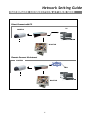
• HARDWARE CONNECTION AT DMR SIDE --------------------------------------------
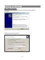
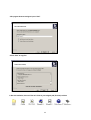
• STATIC IP SETTING--------------------------------------------------------------------------
• DYNAMIC IP SETTING ------------------------------------------------------------------------
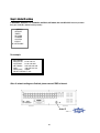
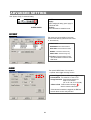
• SOFTWARE OPERATION AT CLIENT SIDE ---------------------------------------------
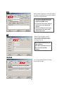
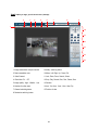
• INTRODUCTION OF BASIC OPERATION ------------------------------------------------
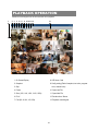
•PLAYBACK OPERATION----------------------------------------------------------------------
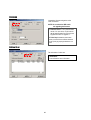
•ADVANCED SETTING--------------------------------------------------------------------------
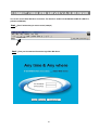
•CONNECT VIDEO WEB SERVER VIA IE BROWSER----------------------------------
TABLE OF CONTENTS
1
1
2
3
5
6
6
8
9
9
10
15
17
18
224
34
35
37
38
41

TABLE OF CONTENTS
Advanced Operation
Advanced Operation
• OPERATION OPTIONS -----------------------------------------------------------------------
• KEY LOCK ----------------------------------------------------------------------------------------
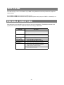
• TROUBLE SHOOTING--------------------------------------------------------------------------
• SPECIFICATIONS -------------------------------------------------------------------------------
Appendix
Appendix
• APPENDIX #1 – INSTALL HDD---------------------------------------------------------------
• APPENDIX #2 – RACK MOUNT---------------------------------------------------------------
• APPENDIX #3 – RECORDING SPEED------------------------------------------------------
• APPENDIX #4 – PIN CONFIGURATIONS--------------------------------------------------
43
44
44
45
46
48
49
50

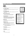
FEATURES
DMR Features
•Remote control via the Internet
•Wavelet Compression Format replaces Time-Lapse VCR + Multiplexer
• 4 Audio inputs / 2 Audio outputs
• On Screen Display and RTC (Real time clock) Function
• Support from 4 channels to 7/9/10/13/16 channels video inputs
• Picture-In-Picture (PIP) is available in live and DMR playback modes
• Motion detection function and 4 level video quality adjustable on each channel
• Alarm Input & Output Function
• Video loss detected on each channel can record up to 160 events
• Power-loss memory function
• Support 2 Removable HDDs, IDE Type
• Quick Multiple Search by date/time, alarm, full list
• Security password protection
1
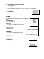
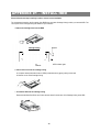
What Do You Get ?
What Do You Get ?
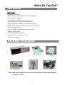
Digital Multiplex Recorder(with HDD cartridge)
User’s Manual
2 Keys for Cartridge Power Adapter and Cord
NOTE : Please check the package to make sure that you receive the complete accessories which includes the
components shown above.
Accessories pack
PACKAGE INCLUDING
CD-ROM

2
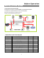
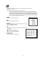
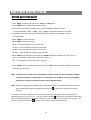
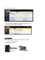
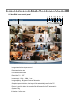
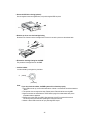
1. Connect cameras and monitor with the DMR.
2. Shown below is one example for connecting the DMR to your existing Observation System.
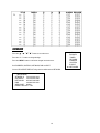
3. Install HDDs(The compatible HDD Brands are listed in the following table.)
Please refer to page.46 Appendix #1 for installation instructions.
The HDDsmust be installed before the DMR is turned on.
INSTALLATION GUIDE
Before Operation
Manufacturer Model Capacity Rotation
HITACHI Deskstar 180 GXP (120 GB) 120GB 7200 rpm
HITACHI Deskstar 7K250, HDS722516VLAT20
160GB
7200rpm
HITACHI Deskstar 7K250, HDS722525VLAT80 250GB 7200rpm
IBM Deskstar 120GXP (80GB) 80GB 7200 rpm
IBM Deskstar 120GXP (120GB) 120GB 7200 rpm
Maxtor DiamondMax 536DX(60GB) 4W060H4 60GB 5400rpm
Maxtor DiamondMax Plus 9 80GB 7200 rpm
Maxtor DiamondMax Plus 9, Model#6Y120L 120GB 7200 rpm
Maxtor DiamondMax Plus 9, Model#6Y160L0 160GB 7200rpm
Seagate Barracuda ATA IV, ST380021A 80GB 7200rpm
Seagate Barracuda ATA V, ST3120023A 120GB 7200 rpm
Seagate Barracuda 7200.7 Plus, ST3160023A 160GB 7200 rpm
Western Digital Caviar WD1200BB-00CAA1 120GB 7200rpm
Western Digital Caviar WD2000BB-00DWA0 200GB 7200rpm
COMPATIBLE HARD DISK BRANDS
Alarm
Sensor
Main Monitor
Power
Camera 1 Camera 16 Call Monitor
Audio Speaker

3
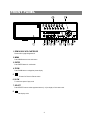
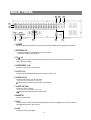
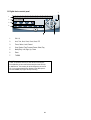
FRONT PANEL
REC
SELECT
MENU
ENTER
ZOOM SLOW
ALARM
HDD
Full
HDD
TIMER
PLAY
REC
Down
Left
Right
POWER
16
7
2 4 6
1 53
8 10 12 14
9 11 13 15
Up
1. REMOVABLE HDD CARTRIDGE
Please refer to page.46 Appendix #1.
2. MENU
Press MENU button to enter main menu.
3. ENTER
Press ENTER button for confirmation.
4. ZOOM
Press ZOOM button to enlarge the picture display.
5.
Press PIP button for Picture in Picture screen.
6. SLOW
To slow down speed of play mode.
7. SELECT
Press SELECT button to select appointed camera (1~16) to displayon full screen mode.
8.
4 channels display mode

4
9.
7, 9, 10, 13 channels display mode
10.
16 channels display mode
11. LED LIGHT
The LED Light is ON under the following conditions.
•HDD : HDD is activated
•HDD Full : HDD is full
•ALARM : If you want to turn off the ALARM LED light, please refer to page.13 and set the
Camera / ALARM item as OFF. (all of thecameras should be set as OFF.)
•TIMER : When Timer is set as Enabled
•PLAY : On Play mode
•REC : On Recording mode
12. CAMERA (1-16)
Press theCamera Select (1-16) to select specified camera.
13. REC
Press REC to start recording.
14. REW / LEFT
•REW:Under DMR play mode, it can play video backward at different speeds. (Press REW again to adjust
speed as 1, 2, 4, 8, 16, 32 times)
•Left : Under setup mode, it works as Leftbutton.
15. PLAY
Press PLAY toplay recorded video.
16. STOP / DOWN
•STOP : Under DMR Record / Play mode, it can stop the action.
•DOWN : Under setup mode, it works as Down button.
17. PAUSE / UP
•Pause : Under DMR play mode, it can pause the action.
•UP : Under setup mode, it works as Up button.
18. FF / Right
•FF : It can play video forward at high speed, and press FF againto adjust speed from 1, 2, 4, 8, 16, 32 times.
•Right : Under setup mode, it can work as Right button.
19. POWER
Press Power to turn ON / OFF the DMR.

5
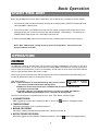
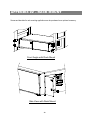
1. POWER
Please use the provided adaptor to connect power cord (Other adaptors are not suitable for this machine).
2. EXTERNAL I/O
•Controlled remotely by an external device or control system.
•Alarm input, external I / O explanation.
3. 75Ω / HI
When using Loop function, please switch to HI. If you don’t use Loop function or disconnect the video
input, please set it as 75Ω.
4. VIDEO INPUT (1-16)
Connect to video source, such as camera.
5. LOOP (1-16)
Connect video signal between Input port and Loop port to make a loop.
6. AUDIO IN (1-4)
Connect to audio source, such as microphone.
•IPS should be set to 25A (for NTSC) or 18A (for PAL)
✻ 4 audio inputs, but users can only select 1 for recording.
7. AUDIO OUT (R/L)
Connect to monitor or speaker.
•IPS should be set to 25A (for NTSC) or 18A (for PAL)
✻ with 2 mono audio outputs from the same source.
8. MONITOR
Connect to Main monitor.
9. CALL
Connect to CALL monitor. Show the Switch Display. When the alarmis triggered, the call monitor will show
the triggered channel for a period of time.
10.LAN
Connect Internet by LAN cable.
BACK PANEL
8 6 7
5
4
1 2
3
10
9

Connect the AC Power Cord with Power Adapter and plug into an electrical outlet. The Red LED indicator light will be
ON and the DMR is in Standby mode.
1.
Press the Power button. The POWER LED will turn from red to orange, and other red LED indicators will turn ON. It
takes approximately 5 to 15 seconds to boot the system with the message : “ HDD Detecting ”. On connecting, the
POWER LED will change to green color, and the Alarm LED will be ON.
2.
6
Before using the DMR, please have the HDDsinstalled ready. (refer to Appendix #1 for installation or removal of HDDs).
START THIS UNIT
Basic Operation
OPERATION
3. Before operating the DMR, please set up the system time first. (for setting system time, please refer to page.12).
NOTE : When “HDD not found” message shows up, please refer to appendix # 1. It may result from the
improper installation of the HDD.
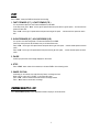
2002 – JAN –01 01:02:03
M● 032GB 080GB
RECORDING
The DMR offers a variety of recording modes, such as continuous recording, scheduled time, or by events. You can set up
recording speed and resolution. You can set these options by selecting MENU / RECORD before recording, please refer to
page.13. Under the recording status, if power is off accidentally, recorded video will still be stored in the HDDs. DMR will
return to original recording situation after power is on again.
On the screen, you will find the date, time, HDD recording type,the amount of available GB left in the HDDsmemory and
the letter “M” represents the method of recording that is occurring.
(OW : HDD Overwrite)
NOTE : 1. When the HDDsare full under O/W Recording mode, previous recorded
files may be overwritten without further warning notices.
2.XXGB on the left side means the left space in the Master HDD andthat at the right side means
the left space in the Slave HDD.
3. If the HDD’s capacity is only 5 GB left, it will buzz for 3 seconds; so as in 4GB, 3GB, 2GB and
1GB. If the O/W Recording mode(NOTE 1) is on, it won’t have the warning buzzer.
There are 4 recording modes in which Recording can occur : Alarm, Timer, Manual and Motion Trigger.
1. ALARM RECORDING
DMR is triggered by an alarm input. Indicated by the letter “A” and will show diagram on the triggered channel.
2. TIMER RECORDING
Recording is scheduled by a Timer. Indicated by the letter “T”.
3. MANUAL RECORDING
Recording is initiated by manually pressing the REC button.Indicated by the letter “M”.
4. MOTION TRIGGER RECORDING
Recording is triggered by motion detection. Indicated by the letter “D”. And show diagram on the triggered channel.

PLAY
Press “ PLAY ” button, the DMR will show the last recording.
1. FAST FORWARD (F.F. ) & FAST REWIND (F.R.)
You can increase speed for Fast Forward and Rewind on the DMR.
In the Play mode, press ” ►► ” once to get 2X speed forward and press twice to get 4X speed,… and the maximum
speed can reach 32X.
Press ”◄◄ ” once to get 1X speed rewind and press twice to get 2X speed, … and the maximum speed can reach
32X.
2. SLOW FORWARD (S.F.) & SLOW REWIND (S.R.)
You can also slow down the speeds of Forward and Rewind on the DMR.
In the Play mode, press the SLOW button and you will enter Slow mode.
Press ” ►► ” once to get 1/2X speed forward and press twice to get 1/4X speed,… and the slowest speed can reach
1/32X.
Press ”◄◄ ” once to get 1/2X speed rewind and press twice to get 1/4X speed, … and the slowest speed can reach
1/32X.
3. PAUSE
It will let you pause the current image displayed on the screen.
4. STOP
Press “ STOP ” button under all circumstance, it will return DMR to live monitoring mode.
5. IMAGE JOG DIAL
It will allow you to manually view video frame-by-frame, one image at a time.
While in PLAY mode, press “ PAUSE ”, it will pause the screen.
Press “ ►► ” button to advance the frozen screen one image forward.
Press “ ◄◄ ” button to move back one image.
CAMERA SELECT (1--16)
Press Camera Select (1-16) to select appointed camera to display on full screen mode.
7

Detailed Menu Setup
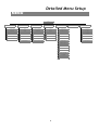
MENU
8
LAST RECORD
FULL LIST
ALARM LIST
MOTION LIST
TIME SEARCH
SEARCH
DAY
START
END
QUALITY
IPS
TIMER ENABLE
TIMER
HDD OVERWRITE
RECORD IPS
RECORD QUALITY
ALARM REC IPS
ALARM REC QUALITY
MOTION TRIGGER RECORD
RECORD
TITLE
DWELL
Brightness / Contrast / Color
ALARM
RECORD
CAMERA
AUDIO INPUT
INT AUDIBLE ALARM
EXT AUDIBLE ALARM
MOTION AUDIBLE ALARM
ALARM DURATION
DWELL TIME
MESSAGE LATCH
TITLE DISPLAY
TIME DISPLAY
TIME
NEW PASSWORD
CLEAR HDD
SYSTEM RESET
SYSTEM EVENT
SEVER IP
GATEWAY
NET MASK
DNS
WEB PORT
RESET DEFAULT
NETWORK
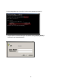
MENU

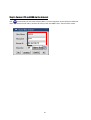
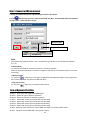
The Menu allows you to configure your DMR settings. Please follow the
steps below to access the Menu :
Press the Menu button. The password screen will appear:
Password: 0000
The default Password is 0000. Press the Enter button to access the Menu.
To key-in the Password, press the “Right” and “Left” buttons to move between numbers, and use the “Up”
and “Down” buttons to input the number.
Press the ENTER button once the correct Password is entered. The MENU options screen will appear.
Note: If you get a message “Password Error”, you might enter an incorrect password.
There are 7 options available in the Main Menu:
SEARCH --------Find recorded list
TIMER ----------Scheduling Record
RECORD -------Record Mode Setup
CAMERA -------Camera Channel Setup
SYSTEM --------System Setup
EVENT ----------Event List
NETWORK------Network Setup
9
Outlined below are the buttons used for Menu setting :
•“Up” and “Down” : Scroll up and down or change values when an option is selected and is blinking
•“Left” and “Right” : Scroll sideways within a menu option that has been selected
•ENTER : Selects a submenu / an option under a submenu for browsing / modification
•MENU : Completes modification of a menu option and exits a menu
ACCESS MENU
MAIN MENU
NOTE :
(MENU)
► SEARCH
TIMER
RECORD
CAMERA
SYSTEM
EVENT
NETWORK

MENU OPTIONS
SYSTEM
10
1. AUDIO INPUT
To choose one of 4 channels to record. (can only select 1 during operation for recording)
2. INT AUDIBLE ALARM
To set the INTERNAL AUDIBLE ALARM. It will be trigged by event occurrence when
the setting is ON.
5. ALARM DURATION
Set the reaction time which was determined by the length of
alarm mode responded to a buzzer. Default setting is 10 sec.
Options are 10 SEC, 15 SEC, 20 SEC, 30 SEC, 1MIN, 2MIN,
3 MIN, 5 MIN, 10 MIN, 15 MIN, 30 MIN, ALWAYS.
6. DWELL TIME
DWELL TIME is the time period that each channel sequentially
shown on call monitor.
7. MESSAGE LATCH
To select whether the DMR messages will disappear after 10
sec or remain on screen. NO is the default setting which the
messages will go away after 10 sec.
NOTE : Video loss, Alarm and Motion messages will be shown
the same as Alarm Duration time.
8. TITLE DISPLAY
To set the title shown on monitor or not.
9. TIME DISPLAY
To set the time format on the DMR.
10. TIME
To set the correct time on the DMR.
3. EXT AUDIBLE ALARM
To set the EXTERNAL AUDIBLE ALARM. It will be trigged by event occurrence when
the setting is ON.
(MENU)
SEARCH
TIMER
RECORD
CAMERA
►SYSTEM
EVENT
NETWORK
4. MOTION AUDIBLE ALARM
To set the MOTION AUDIBLE ALARM. It will be trigged by
motion detection occurrence when the setting is ON.
(SYSTEM)
► AUDIO INPUT : 1
INT AUDIBLE ALARM : ON
EXT AUDIBLE ALARM : ON
MOTION AUDIBLE ALARM : ON
ALARM DURATION : 10 SEC
DWELL TIME : 02 SEC
MESSAGE LATCH : NO
TITLE DISPLAY :ON
TIME DISPLAY : Y/M/D
2003-JAN-02(THU) 17:37:09
NEW PASSWORD : XXXX
CLEAR HDD : NO
SYSTEM RESET : NO

11. NEW PASSWORD : XXXX (Default password : 0000)
To set the new password.
12. CLEAR HDD
Delete all the contents of your HDD. When you choose “YES” on this option, you will be prompted with the
question shown : Press “►” to clear HDD or press ”◄” not to clear HDD.
13. SYSTEM RESET
Reset the system to book to the factory default settings.
11
ALL DATA IN HDD
WILL BE CLEARED
ARE YOU SURE?
(◄ : NO ► : YES )
SEARCH
Press ”ENTER” to confirm SEARCH setup, and the screen will show the following
options.
1. LAST RECORD
Play the last recorded video.
2. FULL LIST
Show a listing of all recorded video sorted by time on the HDD.
D : Motion Recording
M : Manual Recording time
A : Alarm Recording time
T : Timer Recording time
M-HDD : Storage in Master HDD
S-HDD : Storage in Slave HDD
3. ALARM LIST
Show a listing of all recorded video triggered by an Alarm.
NOTE: If there is no Alarm recorded, the screen will
display “EMPTY”.
4. MOTION LIST
Show a listing of all triggered motion detections.
5. TIME SEARCH
Find video recorded on a specific date that is entered.
(SEARCH)
►LAST RECORD
FULL LIST
ALARM LIST
MOTION LIST
TIME SEARCH
(MENU)
► SEARCH
TIMER
RECORD
CAMERA
SYSTEM
EVENT
NETWORK
► 2002-JAN-01 02:32:03 M-HDD
2002-JAN-03 01:02:03 M-HDD
2002-JAN-05 21:12:24 M-HDD
2002-JAN-12 12:57:38 M-HDD
2002-JAN-13 16:16:39 S-HDD
2002-JAN-15 23:55:23 S-HDD
2002-JAN-22 18:22:13 M-HDD
2002-JAN-25 12:52:03 S-HDD
◄: PAGE UP ►: PAGE DOWN
M
M
A
T
D
M
T
D

12
TIMER
1. DAY
Select the day, or days of the week (Mon–Fri / Sat-Sun / Daily) that you wish to schedule
the DMR to auto recording.
NOTE : 1.Special Date could be changed by “Enter”, “Up” and “Down” buttons.
2. If you have selected the specific date and recording timer set from that specific day to a new day,
then the Recording Timer Schedule will be setas a whole week. For specific date of Recording Timer
Schedule, it is not recommended to set End Time over 23:59. For Example:If you set Timer Schedule
Day as Sunday, and START from 11:30, but End on 00:20, then Recording Timer Schedule is setas
from every Sunday's 11:30 to next Sunday's 00:20. If you only want to set Recording Timer Schedule
from every Sunday 11:30 to Monday00:20, then you should set Recording Timer Schedule as Sunday
from 11:30 to 23:59, and Monday from 00:00 to00:20.
2. START
Select the starting time for the recording.
3. END
Select the finishing time for the recording.
4. QUALITY
Select the image quality for the recording. There are four Quality settings :
BEST, HIGH, NORMAL and BASIC.
5. IPS
Stand for Images Per Second and it could let you see Recordsubmenu
for more details.
NTSC-25A、15、08、04、02、01
PAL-18A、12、06、03、02、01
NOTE : “A” means “ Record with Audio”.
6. TIMER ENABLE
Enables / disables Timer recording function.
(TIMER)
DAY START END QUALITY IPS
DAILY 00:00 00:00 BEST 25A
DAILY 00:00 00:00 BEST 25A
DAILY 00:00 00:00 BEST 25A
DAILY 00:00 00:00 BEST 25A
DAILY 00:00 00:00 BEST 25A
DAILY 00:00 00:00 BEST 25A
DAILY 00:00 00:00 BEST 25A
TIMER ENABLE : NO
(MENU)
SEARCH
►TIMER
RECORD
CAMERA
SYSTEM
EVENT
NETWORK

13
RECORD
1. HDD OVERWRITE
Select “YES” to overwrite previous recording video in HDD.
NOTE : When the HDD is full under O/W Recording mode, previous recorded files
may be overwritten without further warning notices.
2. RECORDING IPS
Select the images per second of recording. The options are
as following :
NTSC-25A、15、8、4、2、1
PAL-18A、12、6、3、2、1
NOTE : “A” means “Record with Audio ”.
3. RECORDING QUALITY
There are four quality settings : BEST, HIGH, NORMAL and BASIC.
4. ALARM REC IPS
Select the images per second of recording during an Alarm.The options are as following :
NTSC-25A、15、8、4、2、1
PAL-18A、12、6、3、2、1
NOTE : “A” means “ Record with Audio”.
5. ALARM REC QUALITY
There are four quality settings during an Alarm : BEST, HIGH, NORMAL and BASIC.
6. MOTION TRIGGER RECORDING
When you set up the MOTION DETECTION function (Please refer to Page.15 for MOTION DETECTION SETUP),
1. Select “ON” to set up the motion trigger recording: It can automatically switch from stand-by mode to Recording Mode.
The motion detection will change the scanning sequence and shows and “D” on the monitor.
NOTE: The trigger recording time will depend on ALARM DURATION mode setting (Please refer to page.10 for ALARM DURATION) and it will
record from the last trigger time. For example, when the alarm duration setting is 1 min, the time recording time is from 9:00:00 to 9:01:00.
If the motion detection trigged again at 9:00:40, the trigged recording time will from 9:00:00 to 9:00:40 and 9:00:40 to 9:01:40. The total
recording time is 00:01:40.
2. Select ”OFF”: The screen shows , the motion detection will change the scanning sequence while in recording mode and shows
“M”on the monitor.
3. (Brightness) / (Contrast) / (Color)
Have a video adjustment (Brightness / Contrast / Color) of each channel. The level is from 0 to 9.
4. ALARM
Select LOW / OFF / HIGH for alarm polarity. The default value is LOW.
5. RECORD
Set up which channel you want to record during alarm trigger. The DMR record methods are as below :
EVENT : when alarm input is triggered, DMR will record alarming channel more frequently.
For example : when CH01 is triggered, the recording method will become 1-2-1-3-1-4….
NORMAL : when alarm input is triggered, DMR will record normally as set up.
OFF : when alarm input is triggered, DMR will not record.
(RECORD)
► HDD OVERWRITE: NO
RECORD IPS: 25A
RECORD QUALITY : NORMAL
ALARM REC IPS: 25A
ALARM REC QUALITY : HIGH
MOTION TRIGGER RECORD: ON
CAMERA
1. TITLE
Assign a six-characters title to each camera input. Initially each title is the
camera’s max number.
2. DWELL
Select “ON” to set up the channel auto switching on the call monitor.
(MENU)
SEARCH
TIMER
► RECORD
CAMERA
SYSTEM
EVENT
NETWORK
(MENU)
SEARCH
TIMER
RECORD
► CAMERA
SYSTEM
EVENT
NETWORK

NETWORK
(MENU)
SEARCH
TIMER
RECORD
CAMERA
SYSTEM
EVENT
► NETWORK
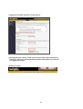
Press the “▲”“▼””◄”“►”buttons to move the cursor.
Press the “+”“-”buttons to change the digit.
Press the “MENU” button to confirm the changes/ to exit the menu.
Set IP ADDRESS, GATEWAY, NET MASK, DNS and PORT.
Choose YES in RESET DEFAULT will go back to default value of NETWORK.
14
(NETWORK)
SERVER IP
GATEWAY
NET MASK
DNS
WEB PORT
RESET DEFAULT NO
192.168.001.010
192.168.001.065
255.255.255.000
168.095.001.001
00080

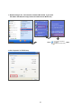
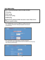
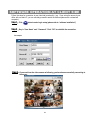
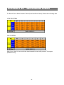
MOTION DETECTION SETUP
1. Press “ MENU “ to enter the menu set up, then “ Down ” to CAMERA setup.
2. Press “ENTER” twice to enter the Motion Detection Setup.
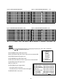
3. Each screen displays the current camera picture overlaid withthe motion targets (as Figure 1).
You can push the button “ Left ” or “ Right ”, ” Up ” or “ Down ” to adjust motion detection in ON or OFF.
4. The targets on each motion setup can be turned to ON or OFF individually. To set up targets, using the
front panel buttons:
àPress “ENTER” to confirm the channel
àPress “ENTER” to enter motion mode
•▲ Up --moves the target cursor up one row at a time.
•▼ Down --moves the target cursor down one row at a time.
•◄ Left --moves the target cursor left one column at a time.
•► Right --moves the target cursor right one column at a time.
àPress “ENTER” to turn the target cursor ON and press “ENTER” again to turn the target cursor OFF. (Figure 1-1)
•Zoom – turns all targets in the current row ON or OFF. (Figure 1-2)
•PIP – turns all targets on the screen ON or OFF. (Figure 1-3)
5. Press “ SLOW “ button to setup the Sensitivity list up to 255 and “ REC “ button to setup the Sensitivity list down to 000.
The default value is set on 32.
NOTE : Sensitivity value is related to motion and brightness change. Low value (as 001) means higher sensitivity
on motion and brightness change. High value (as 255) means lower sensitivity on motion and brightness
change. User can choose the suitable sensitivity value in different locations.
NOTE : When motion trigger recording setting is ON, it can automatically switch from stand-by mode to record mode.The
motion detection will change the scanning sequenceand shows on the monitor. There will be an action as
following:
For example : If the motion is detected on Camera #1, its recording & scanning sequence will be more frequent. The
sequence will be as 1st, 2nd, 1st, 3rd, 1st, … 16th. And channel 1 will show on the screen. If 2nd cameraand 3rd camera
both motion detection are activated, they will be scanning as 1st, 2nd, 3rd, 2nd, 2nd, 3rd, 3rd, 2nd, 3rd, 4th, 2nd, 3rd … and
vice versa. And CH2 & CH3 will show for a period of time which is same as Alarm Duration time.
15
MOTION DETECTION

16
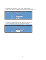
Figure 1 MOTION DETECTION SETUP
1
2 3 4 5 6 7 8 9 10 11 12 13 14 15
--
-- -- -- -- -- -- -- -- -- -- -- -- -- --
032
1
2 3 4 5 6 7 8 9 10 11 12 13 14 15
--
-- -- -- -- -- -- -- -- -- -- -- -- -- --
Figure 1-1 MOTION DETECTION SETUP — 1~15
032
1
2 3 4 5 6 7 8 9 10 11 12 13 14 15
--
-- -- -- -- -- -- -- -- -- -- -- -- -- --
Figure 1-2 MOTION DETECTION SETUP--LINE
032
Figure 1-3 MOTION DETECTION SETUP--ALL
1
2 3 4 5 6 7 8 9 10 11 12 13 14 15
--
-- -- -- -- -- -- -- -- -- -- -- -- -- --
032
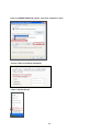
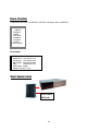
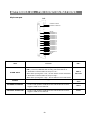
EVENT
There are only 16 recorded events will be shown on a single pageand please press “◄ ” or “► ” to change the
pages or press ▲ + ▼ to CLEAR the EVENT record.
(MENU)
SEARCH
TIMER
RECORD
CAMERA
SYSTEM
► EVENT
NETWORK
M–HDD WARNING 2002-JAN-01 03:00:00
M–HDD LOSS 2002-JAN-01 03:00:00
M–HDD ERROR 2002-JAN-01 03:00:00
S–HDD WARNING 2002-JAN-01 03:00:00
HDD FULL 2002-JAN-01 03:00:00
SYSTEM ERROR 2002-JAN-01 03:00:00
----02 VLOSS 2002-JAN-01 03:00:00
----03 ALARM 2002-JAN-01 03:00:00
◄: PAGE UP ►: PAGE DOWN ▲+▼: CLEAR
M-HDD WARNING: Master HDD might be failed.
M-HDD LOSS: Master HDD does not exist. Now user can use the otherHDD.
M-HDD ERROR: Master HDD might be error
S-HDD WARNING: Slave HDD might be failed
S-HDD LOSS: Slave HDD does not exist. Now user can use the other HDD.
S-HDD ERROR: Slave HDD might be error
HDD FULL: HDD is full
SYSTEM ERROR: System might be failed
----02 VLOSS: Channel: 2 Video loss
----03 ALARM: Channel: 3 External I/O Alarm have triggered
POWER RESTORE : Power restore
La page est en cours de chargement...
La page est en cours de chargement...
La page est en cours de chargement...
La page est en cours de chargement...
La page est en cours de chargement...
La page est en cours de chargement...
La page est en cours de chargement...
La page est en cours de chargement...
La page est en cours de chargement...
La page est en cours de chargement...
La page est en cours de chargement...
La page est en cours de chargement...
La page est en cours de chargement...
La page est en cours de chargement...
La page est en cours de chargement...
La page est en cours de chargement...
La page est en cours de chargement...
La page est en cours de chargement...
La page est en cours de chargement...
La page est en cours de chargement...
La page est en cours de chargement...
La page est en cours de chargement...
La page est en cours de chargement...
La page est en cours de chargement...
La page est en cours de chargement...
La page est en cours de chargement...
La page est en cours de chargement...
La page est en cours de chargement...
La page est en cours de chargement...
La page est en cours de chargement...
La page est en cours de chargement...
La page est en cours de chargement...
La page est en cours de chargement...
La page est en cours de chargement...
-
 1
1
-
 2
2
-
 3
3
-
 4
4
-
 5
5
-
 6
6
-
 7
7
-
 8
8
-
 9
9
-
 10
10
-
 11
11
-
 12
12
-
 13
13
-
 14
14
-
 15
15
-
 16
16
-
 17
17
-
 18
18
-
 19
19
-
 20
20
-
 21
21
-
 22
22
-
 23
23
-
 24
24
-
 25
25
-
 26
26
-
 27
27
-
 28
28
-
 29
29
-
 30
30
-
 31
31
-
 32
32
-
 33
33
-
 34
34
-
 35
35
-
 36
36
-
 37
37
-
 38
38
-
 39
39
-
 40
40
-
 41
41
-
 42
42
-
 43
43
-
 44
44
-
 45
45
-
 46
46
-
 47
47
-
 48
48
-
 49
49
-
 50
50
-
 51
51
-
 52
52
-
 53
53
-
 54
54


Maxtor 777 W V1.0 Manuel utilisateur
- Catégorie
- Des caméras de sécurité
- Taper
- Manuel utilisateur
- Ce manuel convient également à
dans d''autres langues
- English: Maxtor 777 W V1.0 User manual
Documents connexes
Autres documents
-
Sanyo DSR-3000 Manuel utilisateur
-
Monacor DMR-184 Le manuel du propriétaire
-
Deltaco DVR Manuel utilisateur
-
Swann DVR4-5500 Operating Instructions Manual
-
Samsung SCR-3000P Manuel utilisateur
-
-
-
Velleman CCTVPROM15 Guide d'installation
-
-
Lorex Technology L15LD420 Series Manuel utilisateur