Winmate R17IH3S-MLA1-89 Manuel utilisateur
- Catégorie
- Téléviseurs
- Taper
- Manuel utilisateur
Ce manuel convient également à

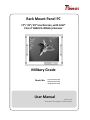
Rack Mount Panel PC
17”/ 19”/ 24” touchscreen, with Intel®
Core i7 4650U 3.30GHz processor
Military Grade
User Manual
Version 1.0
Document Part Number: 9152111I100U
Model No:
R17IH3S-MLA1-89
R19IH3S-MLA3-89
W24IH3S-MLS1-89

User Manual
ii
Preface
Copyright Notice
No part of this document may be reproduced, copied, translated, or transmitted in any form
or by any means, electronic or mechanical, for any purpose, without the prior written
permission of the original manufacturer.
Trademark Acknowledgement
Brand and product names are trademarks or registered trademarks of their respective
owners.
Disclaimer
We reserve the right to make changes, without notice, to any product, including circuits
and/or software described or contained in this manual in order to improve design and/or
performance. We assume no responsibility or liability for the use of the described product(s)
conveys no license or title under any patent, copyright, or masks work rights to these
products, and make no representations or warranties that these products are free from
patent, copyright, or mask work right infringement, unless otherwise specified. Applications
that are described in this manual are for illustration purposes only. We make no
representation or guarantee that such application will be suitable for the specified use
without further testing or modification.
Warranty
Our warranty guarantees that each of its products will be free from material and
workmanship defects for a period of one year from the invoice date. If the customer discovers
a defect, we will, at his/her option, repair or replace the defective product at no charge to the
customer, provide it is returned during the warranty period of one year, with transportation
charges prepaid. The returned product must be properly packaged in its original packaging to
obtain warranty service. If the serial number and the product shipping data differ by over 30
days, the in-warranty service will be made according to the shipping date. In the serial
numbers the third and fourth two digits give the year of manufacture, and the fifth digit
means the month (e. g., with A for October, B for November and C for December).
For example, the serial number 1W15Axxxxxxxx means October of year 2015.

User Manual
iii
Customer Service
We provide a service guide for any problem by the following steps: First, visit the website of
our distributor to find the update information about the product. Second, contact with your
distributor, sales representative, or our customer service center for technical support if you
need additional assistance.
You may need the following information ready before you call:
Product serial number
Software (OS, version, application software, etc.)
Detailed description of the problem
The exact wording of error messages
In addition, free technical support is available from our engineers every business day. We are
always ready to give advice on application requirements or specific information on the
installation and operation of any of our products.

User Manual
iv
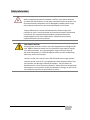
Advisory Conventions
Four types of advisories are used throughout the user manual to provide helpful information or to
alert you to the potential for hardware damage or personal injury. These are Notes, Important,
Cautions, and Warnings. The following is an example of each type of advisory.
NOTE:
A note is used to emphasize helpful information
IMPORTANT:
An important note indicates information that is important for you to know.
CAUTION/ ATTENTION
A Caution alert indicates potential damage to hardware and explains how to avoid the
potential problem.
Une alerte d’attention indique un dommage possible à l’équipement et explique
comment éviter le problème potentiel.
WARNING! / AVERTISSEMENT!
An Electrical Shock Warning indicates the potential harm from electrical hazards and
how to avoid the potential problem.
Un Avertissement de Choc Électrique indique le potentiel de chocs sur des
emplacements électriques et comment éviter ces problèmes.
ALTERNATING CURRENT / MISE À LE TERRE!
The Protective Conductor Terminal (Earth Ground) symbol indicates the potential
risk of serious electrical shock due to improper grounding.
Le symbole de Mise à Terre indique le risqué potential de choc électrique grave à
la terre incorrecte.

User Manual
v
Safety Information
WARNING! / AVERTISSEMENT!
Always completely disconnect the power cord from your chassis whenever
you work with the hardware. Do not make connections while the power is on.
Sensitive electronic components can be damaged by sudden power surges.
Only experienced electronics personnel should open the PC chassis.
Toujours débrancher le cordon d’alimentation du chassis lorsque vous
travaillez sur celui-ci. Ne pas brancher de connections lorsque l’alimentation
est présente. Des composantes électroniques sensibles peuvent être
endommagées par des sauts d’alimentation. Seulement du personnel
expérimenté devrait ouvrir ces chassis.
CAUTION/ATTENTION
Always ground yourself to remove any static charge before touching the CPU
card. Modern electronic devices are very sensitive to static electric charges.
As a safety precaution, use a grounding wrist strap at all times. Place all
electronic components in a static-dissipative surface or static-shielded bag
when they are not in the chassis.
Toujours verifier votre mise à la terre afin d’éliminer toute charge statique
avant de toucher la carte CPU. Les équipements électroniques moderns sont
très sensibles aux décharges d’électricité statique. Toujours utiliser un
bracelet de mise à la terre comme précaution. Placer toutes les composantes
électroniques sur une surface conçue pour dissiper les charge, ou dans un sac
anti-statique lorsqu’elles ne sont pas dans le chassis.

User Manual
vi
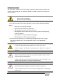
Safety Precautions
For your safety carefully read all the safety instructions before using the device. All
cautions and warnings on the equipment should be noted. Keep this user manual for
future reference.
CAUTION/ATTENTION
Do not cover the openings!
Ne pas couvrir les ouvertures!
*Let service personnel to check the equipment in case any of the following problems
appear:
o The power cord or plug is damaged.
o Liquid has penetrated into the equipment.
o The equipment has been exposed to moisture.
o The equipment does not work well or you cannot get it to work according
to the user manual.
o The equipment has been dropped and damaged.
o The equipment has obvious signs of breakage.
Do not leave this equipment in an uncontrolled environment where the storage
temperature is below -20°C (-4°F) or above 60°C (140°F). It may damage the
equipment.
CAUTION/ATTENTION
Use the recommended mounting apparatus to avoid risk of injury.
Utiliser l’appareil de fixation recommandé pour éliminer le risque de
blessure.
WARNING! / AVERTISSEMENT!
Only use the connection cords that come with the product. When in doubt,
please contact the manufacturer.
Utiliser seulement les cordons d’alimentation fournis avec le produit. Si vous
doutez de leur provenance, contactez le manufacturier.
WARNING!/ AVERTISSEMENT!
Always ground yourself against electrostatic damage to the device.
Toujours vérifier votre mise à la terre afin que l’équipement ne se décharge
pas sur vous.

User Manual
vii
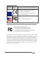
Important Information
Countries/
Area
Symbol
This equipment complies with essential requirements of:
European
Union
Electromagnetic Compatibility Directive(2014/30/EU)
Low Voltage Directive (2014/35/EU)
Restrictions of the use of certain hazardous substances
(RoHS) Directive (2011/65/EU)
USA
FCC Part 15 Subpart B Regulations Class B
Federal Communications Commission Radio Frequency Interface Statement
This device complies with part 15 FCC rules.
Operation is subject to the following two conditions:
This device may not cause harmful interference.
This device must accept any interference received including
interference that may cause undesired operation.
This equipment has been tested and found to comply with the limits for a class "A" digital
device, pursuant to part 15 of the FCC rules. These limits are designed to provide
reasonable protection against harmful interference when the equipment is operated in a
commercial environment. This equipment generates, uses, and can radiate radio frequency
energy and, if not installed and used in accordance with the instruction manual, may cause
harmful interference to radio communications. Operation of this equipment in a residential
area is likely to cause harmful interference in which case the user will be required to correct
the interference at him own expense.

User Manual
viii
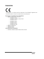
European Union
This equipment is in conformity with the requirement of the following EU legislations and
harmonized standards. Product also complies with the Council directions.
Electromagnetic Compatibility Directive (2014/30/EU)
EN55024: 2010 EN 55022: 2010 Class B
o IEC61000-4-2: 2009
o IEC61000-4-3: 2006+A1: 2007+A2: 2010
o IEC61000-4-4: 2012
o IEC61000-4-5: 2014
o IEC61000-4-6: 2013
o IEC61000-4-8: 2010
o IEC61000-4-11: 2004
EN55022: 2010/AC:2011
EN61000-3-2:2014
EN61000-3-3:2013
Low Voltage Directive (2014/30/EU)
EN 60950-1:2006/A11:2009/A1:2010/A12:2011/ A2:2013

User Manual
ix
Revision History
Version
Date
Note
Author
1.0
20-June-2016
Initial release
Tom Huang

User Manual
x
Contents
Preface ........................................................................................................................................ ii
1 Introduction ............................................................................................................................ 13
1.1 Product Features ................................................................................................................ 13
1.2 Hardware Specifications .................................................................................................... 14
1.3 Software Support ............................................................................................................... 15
1.4 Packing List ......................................................................................................................... 16
1.5 Appearance ........................................................................................................................ 17
1.5.1 Appearance ............................................................................................................. 17
1.5.2 On-Screen Display Control ...................................................................................... 18
1.6 Dimensions ......................................................................................................................... 19
1.6.1 Dimensions 17” ....................................................................................................... 19
1.6.2 Dimensions 19” ....................................................................................................... 20
1.6.3 Dimensions 24” ....................................................................................................... 21
2 Getting Started........................................................................................................................ 23
2.1 Powering On ....................................................................................................................... 23
2.1.1 Power Considerations ............................................................................................. 23
2.1.2 Connecting the Power ............................................................................................. 24
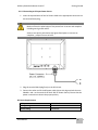
2.2 Connecting Other Devices ................................................................................................. 26
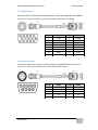
2.2.1 AC Power IN Connector ........................................................................................... 26
2.2.2 VGA Connector ........................................................................................................ 27
2.2.3 RS-232 Connector .................................................................................................... 27
2.2.4 USB 2.0 A Type Connector ....................................................................................... 28
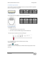
2.2.5 LAN Connector......................................................................................................... 28
2.4 Turning ON /OFF ................................................................................................................ 28
3 Mounting Solutions ................................................................................................................. 30
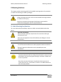
3.1 Cable Mounting Considerations ........................................................................................ 30
3.2 Safety Precautions ............................................................................................................. 31
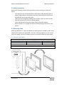
3.3 Mounting Guide ................................................................................................................. 31
3.3.1 Console / Rack Mount ............................................................................................. 31
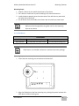
3.3.2 VESA Mount ............................................................................................................. 32

User Manual
xi
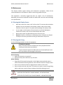
4 Maintenance ........................................................................................................................... 35
4.1 Cleaning the Display Screen ............................................................................................... 35
4.2 Cleaning the Casing ............................................................................................................ 35
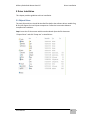
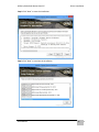
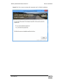
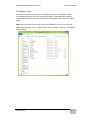
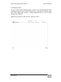
5 Driver Installation ................................................................................................................... 37
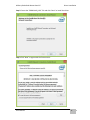
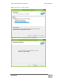
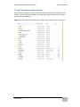
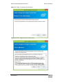
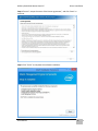
5.1 Chipset Driver..................................................................................................................... 37
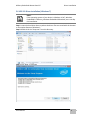
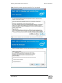
5.2 Graphics Driver .................................................................................................................. 40
5.3 Audio Driver ....................................................................................................................... 43
5.4 Ethernet Driver .................................................................................................................. 45
5.5 Intel® Management Engine Software ................................................................................ 48
5.6 USB 3.0 Driver Installation (Windows 7) ............................................................................ 51
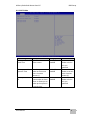
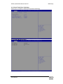
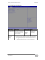
6 BIOS Setup .............................................................................................................................. 56
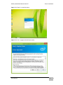
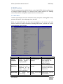
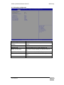
6.1 How and When to Use BIOS Setup .................................................................................... 56
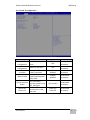
6.2 BIOS Functions ................................................................................................................... 57
6.2.1 Main Menu .............................................................................................................. 57
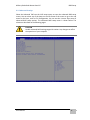
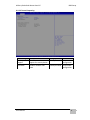
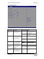
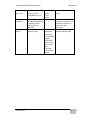
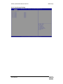
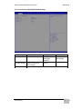
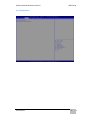
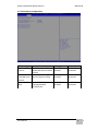
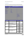
6.2.2 Advanced Settings ................................................................................................... 58
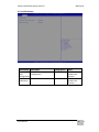
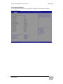
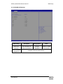
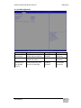
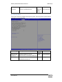
6.2.3 Chipset Menu .......................................................................................................... 72
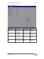
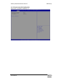
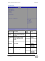
6.2.4 Boot Menu ............................................................................................................... 78
6.2.5 Security Menu ......................................................................................................... 79
6.2.6 Save & Exit ............................................................................................................... 80
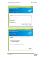
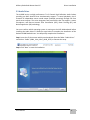
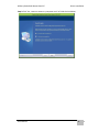
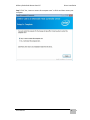
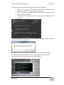
6.3 Using Recovery Wizard to Restore Computer ................................................................... 81
7 Technical Support .................................................................................................................... 84
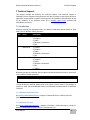
7.1 Introduction ....................................................................................................................... 84
7.1.1 Winmate Download Center ..................................................................................... 84
7.1.2 Winmate File Share ................................................................................................. 84
7.2 Problem Report Form ........................................................................................................ 85
Appendix A MIL-STD-810F/G Compliance ................................................................................... 87
A1 MIL-STD-810F/G Compliance ............................................................................................. 87
Appendix B MIL-STD-461E/F Compliance .................................................................................... 89
B1 MIL-STD-461E/F Compliance .............................................................................................. 89

Military Grade Rack Mount Panel PC Introduction
User Manual
12
Introduction
This chapter gives you product overview,
describes features and hardware specification.
You will find all accessories that come with the
Panel PC in the packing list.

Military Grade Rack Mount Panel PC Introduction
User Manual
13
1 Introduction
Military Grade Panel PCs feature low power high performance CPU with fanless design.
Anti-corrosive coating with aluminum alloy housing withstands the harshest military
environments. Armored connectors MIL-DTL-38999 (type I and III) initially developed
for aerospace industry perfectly fit in our Military grade product line.
Withstanding rigors of harsh environments and tough weather conditions these Panel
PCs meet the most demanding requirements. Suitable for Army Headquarters and
being connected to mobile devices on the field Panel PC can provide up-to-date
information for immediate commands.
1.1 Product Features
Military Grade Rack Mount Panel PCs offer the following features:
Intel® Core i7 4650U 3.30GHz processor.
Fanless, streamlined enclosure for highly efficient heat dissipation.
Aluminum housing with anti-corrosive coating.
5-wire resistive touch.
Convenient on-screen display control.
Built-in Light Sensor for auto brightness control.
AC 110~240V Power input (default) with isolation DC 9~36V (Optional).
Flush Rack / Rack Mount mechanical design (8U).
Military Grade connectors (MIL-DTL-38999/1 and 38999/3).
Compliance with military standard MIL-STD-810G/F.

Military Grade Rack Mount Panel PC Introduction
User Manual
14
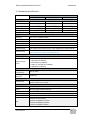
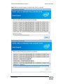
1.2 Hardware Specifications
Model Name
R17IH3S-MLA1-89
R19IH3S-MLA3-89
W24IH3S-MLS1-89
Display:
Size
17”
19”
24”
Resolution
1280 x 1024
1280 x 1024
1920 x 1200
Brightness
350 cd/
(typ.)
350 cd/
(typ.)
300 cd/
(typ.)
Contrast Ratio
1000:1 (typ.)
1000:1 (typ.)
1000:1 (typ.)
Viewing Angle
-85~85(H);-80~80(V)
-85~85(H);-80~80(V)
-89~89(H);-89~89(V)
Display colors
16.7M (colors)
System:
Processor
Intel® Core™ i7 4650U 3.30GHz
BIOS
AMI 16Mbit Flash
System Memory
1 x SO-DIMM DDR3L 1600 (default 4GB)
System Chipset
Intel® HD Graphics 5000
Storage
mSATA SSD (default 64GB)
LAN Controller
Intel® Ethernet Controller 1211-AT + Intel® Gigabit Etherne PHY 1218-LM
Expansion Slot
1 x Mini PCIe slot (for USB module)
*For PCI expansion customized housing required.
Input/ Output:
Plug & Play
VESA DDC 1/2B
Back panel I/O
ports
1 x Power Input (MIL-DTL-38999/1)
1 x VGA (MIL-DTL-38999/3)
1 x RS232 (MIL-DTL-38999/3)
1 x USB 2.0 A Type (MIL-DTL-38999/3)
1 x LAN (MIL-DTL-38999/3)
Environment and Mechanical:
Operating
Temperature
-20°C to +60°C
Operating
Humidity
95%RH ±3%
Power Specifications:
Power Input
Default AC 110~240V IN
Optional isolation DC 9~36V IN
Ordering Information (optional):
Touch
5-wire resistive / 5-wire resistive with EMI coating
Glass
EMI coating glass (default AR glass)
Storage
mSATA SSD up to 256GB
RAM
SO-DIMM DDR3 1666, up to 8GB
Power
Optional isolation 9~36V DC IN
OS
Windows 10 IoT Enterprise
Windows Embedded 8.1 Industry
Windows Embedded 8 Standard
Windows Embedded Standard 7

Military Grade Rack Mount Panel PC Introduction
User Manual
15
1.3 Software Support
Winmate provide all necessary drivers and Software Development Kit (SDK).
Drivers:
Chipset Driver
Graphics Driver
Audio Driver
Ethernet Driver
Intel ® Management Engine Software
USB 3.0 Driver (for Windows 7)
SDK:
Watchdog SDK

Military Grade Rack Mount Panel PC Introduction
User Manual
16
1.4 Packing List
Carefully remove the box and unpack your device. Please check if all the items listed
below are inside your package. If any of these items are missing or damaged contact us
immediately.
Standard factory shipment list:
Panel PC
User Manual (Hardcopy)
CD-ROM with Driver Utility
and User Manual
Power cord
MIL-DTL-38999/1
VGA Cable
MIL-DTL-38999/3
RS-232 Cable
MIL-DTL-38999/3

Military Grade Rack Mount Panel PC Introduction
User Manual
17
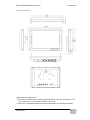
1.5 Appearance
This section includes appearance and input/ output connectors’ layout.
1.5.1 Appearance
LAN
VGA
RS-232
USB 2.0
AC IN
Ground
Display
OSD Panel
VESA
M4 Nut

Military Grade Rack Mount Panel PC Introduction
User Manual
18
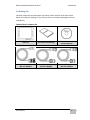
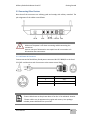
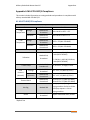
1.5.2 On-Screen Display Control
On-Screen Display (OSD) is a user-friendly interface to remote the display function and
to adjust the display’s image properties. It also supports special Hot Keys for easy
control, such as auto-adjustment and brightness control for backlight.
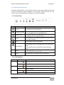
1.5.2.1 Control Keys
Icon
Button
Function
Power
Turn ON or turn OFF the Panel PC.
Brightness DOWN
Decrease the brightness of the display screen, or allows
user to navigate items of a single OSD menu.
Brightness UP
Increase the brightness of the display screen, or allows user
to navigate items of a single OSD menu.
Night
Tap this button to enter NIGHT MODE to increase visibility
in low-light conditions.
Day
Tap this button to enter DAY MODE.
Auto/ Manual
Tap the button once to AUTOMATICALLY adjust brightness
mode.
Press the button again to MANUALLY adjust brightness
mode.
Reset
Clear any pending errors or events and brings a system to
normal condition or an initial state.
LOCK
Tap this button to lock the function of OSD panel.
1.5.2.2 LED Indicators
Indicator
Color
Definition
PWR
Green
Power is ON and the device functions normally
Orange
Panel PC is suspended
HDD
Green
HDD is active
OFF
HDD is inactive
LOCK
Red
The function of OSD buttons is locked
OFF
Lock function disabled

Military Grade Rack Mount Panel PC Introduction
User Manual
19
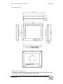
1.6 Dimensions
This section includes mechanical drawing and dimensions of Panel PCs.
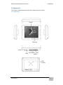
1.6.1 Dimensions 17”
*Measurements shown in mm.
**Tolerance of all dimensions is shown as follow 0~30 mm ± 0.1 mm, 30~50 mm ± 0.15
mm, 50~120 mm ± 0.2 mm, above 120 mm ± 0.25 mm.
***Note: this is a simplified drawing and some components are not marked in detail.

Military Grade Rack Mount Panel PC Introduction
User Manual
20
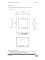
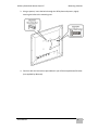
1.6.2 Dimensions 19”
*Measurements shown in mm.
**Tolerance of all dimensions is shown as follow 0~30 mm ± 0.1 mm, 30~50 mm ± 0.15
mm, 50~120 mm ± 0.2 mm, above 120 mm ± 0.25 mm.
***Note: this is a simplified drawing and some components are not marked in detail.
La page est en cours de chargement...
La page est en cours de chargement...
La page est en cours de chargement...
La page est en cours de chargement...
La page est en cours de chargement...
La page est en cours de chargement...
La page est en cours de chargement...
La page est en cours de chargement...
La page est en cours de chargement...
La page est en cours de chargement...
La page est en cours de chargement...
La page est en cours de chargement...
La page est en cours de chargement...
La page est en cours de chargement...
La page est en cours de chargement...
La page est en cours de chargement...
La page est en cours de chargement...
La page est en cours de chargement...
La page est en cours de chargement...
La page est en cours de chargement...
La page est en cours de chargement...
La page est en cours de chargement...
La page est en cours de chargement...
La page est en cours de chargement...
La page est en cours de chargement...
La page est en cours de chargement...
La page est en cours de chargement...
La page est en cours de chargement...
La page est en cours de chargement...
La page est en cours de chargement...
La page est en cours de chargement...
La page est en cours de chargement...
La page est en cours de chargement...
La page est en cours de chargement...
La page est en cours de chargement...
La page est en cours de chargement...
La page est en cours de chargement...
La page est en cours de chargement...
La page est en cours de chargement...
La page est en cours de chargement...
La page est en cours de chargement...
La page est en cours de chargement...
La page est en cours de chargement...
La page est en cours de chargement...
La page est en cours de chargement...
La page est en cours de chargement...
La page est en cours de chargement...
La page est en cours de chargement...
La page est en cours de chargement...
La page est en cours de chargement...
La page est en cours de chargement...
La page est en cours de chargement...
La page est en cours de chargement...
La page est en cours de chargement...
La page est en cours de chargement...
La page est en cours de chargement...
La page est en cours de chargement...
La page est en cours de chargement...
La page est en cours de chargement...
La page est en cours de chargement...
La page est en cours de chargement...
La page est en cours de chargement...
La page est en cours de chargement...
La page est en cours de chargement...
La page est en cours de chargement...
La page est en cours de chargement...
La page est en cours de chargement...
La page est en cours de chargement...
La page est en cours de chargement...
La page est en cours de chargement...
-
 1
1
-
 2
2
-
 3
3
-
 4
4
-
 5
5
-
 6
6
-
 7
7
-
 8
8
-
 9
9
-
 10
10
-
 11
11
-
 12
12
-
 13
13
-
 14
14
-
 15
15
-
 16
16
-
 17
17
-
 18
18
-
 19
19
-
 20
20
-
 21
21
-
 22
22
-
 23
23
-
 24
24
-
 25
25
-
 26
26
-
 27
27
-
 28
28
-
 29
29
-
 30
30
-
 31
31
-
 32
32
-
 33
33
-
 34
34
-
 35
35
-
 36
36
-
 37
37
-
 38
38
-
 39
39
-
 40
40
-
 41
41
-
 42
42
-
 43
43
-
 44
44
-
 45
45
-
 46
46
-
 47
47
-
 48
48
-
 49
49
-
 50
50
-
 51
51
-
 52
52
-
 53
53
-
 54
54
-
 55
55
-
 56
56
-
 57
57
-
 58
58
-
 59
59
-
 60
60
-
 61
61
-
 62
62
-
 63
63
-
 64
64
-
 65
65
-
 66
66
-
 67
67
-
 68
68
-
 69
69
-
 70
70
-
 71
71
-
 72
72
-
 73
73
-
 74
74
-
 75
75
-
 76
76
-
 77
77
-
 78
78
-
 79
79
-
 80
80
-
 81
81
-
 82
82
-
 83
83
-
 84
84
-
 85
85
-
 86
86
-
 87
87
-
 88
88
-
 89
89
-
 90
90


Winmate R17IH3S-MLA1-89 Manuel utilisateur
- Catégorie
- Téléviseurs
- Taper
- Manuel utilisateur
- Ce manuel convient également à
dans d''autres langues
- English: Winmate R17IH3S-MLA1-89 User manual
Documents connexes
-
 Winmate R17IH3S-MLA1-89 Manuel utilisateur
-
 Winmate W24L100-RKS1ML Manuel utilisateur
-
 Winmate W24L100-MLA2FP Manuel utilisateur
-
 Winmate R19IHAT-66EX Manuel utilisateur
-
 Winmate M133KML(HB) Series Guide de démarrage rapide
-
 Winmate I330EAC-IKW Guide de démarrage rapide
-
 Winmate EAC PRO-IK90 Guide de démarrage rapide
-
 Winmate FM07A Manuel utilisateur
-
 Winmate Military M320TF-MIL Manuel utilisateur
-
 Winmate R15L100-MLC3HB Manuel utilisateur


Autres documents
-
Silicon Power SP010TBPHDA10S2K Fiche technique
-
Adlink SETO-1000 Manuel utilisateur
-
Kingston DATATRAVELER LOCKER G2/DTLPG2 Le manuel du propriétaire
-
3M Computer Monitor UMUV.10-045V2 Manuel utilisateur
-
Kingston Technology Computer Drive DTLPG3 Manuel utilisateur
-
SICK IT6300DPM/IT6320DPM Mode d'emploi