
Crystal Vision Ltd., Lion Technology Park, Station Road East, Whittlesford, Cambridge, CB22 4WL, England.
E-mail: [email protected] Website: www.crystalvision.tv Tel: +44(0) 1223 497049 Fax: +44(0) 1223 497059
X-KEY
Digital effects keyer

X-KEY Effects Keyer User Manual 22/12/98 page 2 of 28
X-KEY Digital Effects Keyer
USERS MANUAL
Xkeyman6.doc CRS 22/12/98
Panel S/W 1.4.2 onwards
XKEY S/W 1.8.0 onwards
CONTENTS
INTRODUCTION ............................................................................................................................................................ 3
MIX OR WIPE .............................................................................................................................................................. 3
LINEAR KEY ............................................................................................................................................................... 3
CHROMA-KEY MODE ............................................................................................................................................... 3
ORDERING INFORMATION...................................................................................................................................... 4
SPECIFICATION.......................................................................................................................................................... 4
MECHANICAL ......................................................................................................................................................... 4
INPUTS..................................................................................................................................................................... 4
OUTPUTS (SDI)....................................................................................................................................................... 4
CONTROL ................................................................................................................................................................ 5
INSTALLATION INFORMATION............................................................................................................................... 6
TIMING CONSIDERATIONS ..................................................................................................................................... 6
VIDEO CONNECTIONS FOR FR1-2XKEY............................................................................................................... 6
REMOTE CONNECTIONS FOR FR1-2XKEY........................................................................................................... 6
UPPER REMOTE..................................................................................................................................................... 6
UPPER RS422A........................................................................................................................................................ 6
UPPER RS422B........................................................................................................................................................ 7
UPPER RS232 .......................................................................................................................................................... 7
REMOTE CONNECTIONS FOR PAN-XKEY............................................................................................................ 8
RS232........................................................................................................................................................................ 8
+6VDC INPUT CONNECTOR FOR PAN-XKEY ...................................................................................................... 9
CONTROL CABLE FOR RS422 CONTROL OF A SINGLE X-KEY........................................................................ 9
CONTROL CABLE FOR RS232 CONTROL OF A SINGLE XKEY......................................................................... 9
CONTROL CABLE FOR RS422 CONTROL OF MULTIPLE X-KEY MODULES.................................................. 9
DIP SWITCHES ON X-KEY BOARD....................................................................................................................... 10
SW1......................................................................................................................................................................... 10
SW2......................................................................................................................................................................... 10
LINK POSITIONS ON X-KEY MODULE ................................................................................................................ 11
SOFTWARE UPGRADES ON X-KEY MODULE.................................................................................................... 11
GETTING ACCESS TO THE PAN-XKEY CPU....................................................................................................... 11
SOFTWARE UPGRADES ON PAN-XKEY CONTROL PANEL ............................................................................ 12
OPERATION INSTRUCTIONS .................................................................................................................................. 13
GETTING STARTED................................................................................................................................................. 13
MODES OF OPERATION.......................................................................................................................................... 13
USING THE X-KEY AS A CHROMA KEYER ........................................................................................................ 13
DETAILED DESCRIPTION OF MENUS.................................................................................................................. 15
Switch On menu ...................................................................................................................................................... 15
CHROMA Top Menu .............................................................................................................................................. 15
MIX Top Menu ........................................................................................................................................................ 21
KEY Top Menu........................................................................................................................................................ 21
WIPE Top Menu...................................................................................................................................................... 25
OUTPUT Top Menu................................................................................................................................................ 25
MEMORY Top Menu .............................................................................................................................................. 27
REMOTE Top Menu ............................................................................................................................................... 27

X-KEY Effects Keyer User Manual 22/12/98 page 3 of 28
X-KEY Digital Effects Keyer
USERS MANUAL
INTRODUCTION
The Crystal Vision X-KEY Digital Effects Keyer has simple mix, wipe and key functions, together
with a high quality linear chroma-keyer. Its small size and low cost makes it suitable for multi-
channel keying in live applications. It is especially useful in virtual studios where a chroma-key
function can be provided for each camera so that the studio mixer inputs are already combined with
the "set" allowing full preview of the virtual images. Two modules can be fitted into a 1U frame,
and are controlled by a remote panel. A single remote panel can be used to control up to ten units.
The keyer has 2 picture inputs, an external key input, a combined picture output, and a processed
key output (all serial digital). The combined picture output can be used to preview inputs, or
processed background or foreground. Modes of Operation are: MIX, WIPE, KEY and CHROMA-
KEY.
MIX OR WIPE
In these modes the unit will perform a mix or wipe between 2 video sources, or between one video
source and an internal colour matte. The mix or wipe is either controlled manually or by setting an
auto-transition triggered from the control panel or from remote control. The internal wipe pattern
generator has a number of simple wipes including horizontal, vertical, horizontal blind, vertical
blind, cross or box.
LINEAR KEY
In this mode the unit will cut a hole in a video picture in the shape of the external key signal and fill
it with either another video picture or a colour from the internal matte generator. The key signal can
be amplified, offset and inverted. This is used to add captions, graphics or logos to a video source.
The key processing can be used to fade the “logo” in and out either manually or as a timed
transition.
The keying process can either be multiplicative, or additive depending on the sources to be
combined. Additive keying is used when the foreground is already shaped onto a black background
as in some caption generators, or when the foreground and key signals are the same, (self keying).
Additive keying prevents aliasing effects of shaping a signal that is already shaped ready for keying
(often seen as a black outline to the character).
CHROMA-KEY MODE
The X-KEY effects keyer has a complete chroma-key system that generates the key signal from the
foreground input and produces a combined output. The key and foreground processing allow many
fine adjustments that help eliminate the difficulties of the process and make it easier to create a
realistic effect. The linear keying allow sophisticated effects with transparent and reflective
elements in the foreground (water, glass, mirrors etc). Both additive keying (with blue suppressed to

X-KEY Effects Keyer User Manual 22/12/98 page 4 of 28
black) and conventional keying are available together with external key input for graphics in the
foreground, and a garbage matte generator.
ORDERING INFORMATION
X-KEY Effects Keyer Module (Includes Chroma
Keyer
FR1-2XKEY 1U Frame for up to 2 XKEY modules.
Includes all rear connections and PSU
PAN-KEY Remote Control panel for up to 10
XKEY modules.
SPECIFICATION
MECHANICAL
1U frame holds up to two XKEY modules.
525mm deep. Board and PSU removable from front.
POWER SUPPLY 85 to 264Volt, 75 watts.
Weight with 2 modules 8 Kg
Remote Control Panel for up to 10 modules
19” 2U high 60mm deep, bench or panel mounting.
Weight 2 Kg
Remote RS232/422 control. With some GPI functions.
Power for the remote panel is 6 volts and either comes from the main frame on the control cable (up
to 15 meters) or from external dc supply. (A suitable low voltage converter is supplied with the
control panel, and has IEC input 100 to 250 volts)
A short remote control lead with internal power connection is supplied with the control panel
INPUTS
I/P A/ Foreground (SDI)
I/P B/ Background (SDI)
Inputs A & B have serial LOOP outputs
Key/Alpha Key (SDI)
Analogue Syncs Reference with loop output
OUTPUTS (SDI)
MAIN x 2
Main can be combined output, or select preview from inputs, or processed foreground or
background, or key.
KEY x 2 (after processing).

X-KEY Effects Keyer User Manual 22/12/98 page 5 of 28
CONTROL
RS232 or RS422 multi-drop
19,200 baud, 8 bit no parity

X-KEY Effects Keyer User Manual 22/12/98 page 6 of 28
INSTALLATION INFORMATION
The X-KEY module plugs into the FR1-2XKEY 1U frame. This will hold one or two modules. The
two modules have entirely independent connections on the rear panel for video inputs outputs and
control.
The X-KEY module is controlled by the PAN-XKEY remote control panel. If more than one X-
KEY module is intended to be controlled from the same remote control panel then it is necessary to
connect the RS422 ports of all the X-KEY modules together with external wiring and also to set the
DIP switches on the front of each X-KEY module to give them a separate address.
TIMING CONSIDERATIONS
1 Analogue reference is required for each XKEY module
2 Inputs must be within a 64us timing window.
3 Delay of the unit is no more than 1 line depending on the relative delay of syncs to SDI
input.
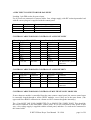
VIDEO CONNECTIONS FOR FR1-2XKEY
There are identical video connections for the upper and lower modules in the frame.
Connections from right hand side are:
FGND: SDI Foreground input.
FGND LOOP SDI Foreground active loop output
KEYIN SDI Key input (optional alpha key for chroma key mode)
BCKGND SDI Background input
BCKGND LOOP SDI Background active loop output
SYNC Analogue mixed sync input or black and burst
SYNC LOOP Passive loop of analogue sync input.
OUT1/OUT2 SDI main output
KEY OUT (x2) SDI combined key output
REMOTE CONNECTIONS FOR FR1-2XKEY
UPPER REMOTE
15 way D type plug.
For future use only
UPPER RS422A
15 way D type socket

X-KEY Effects Keyer User Manual 22/12/98 page 7 of 28
This is the main control port. Use this or the RS232 port to control the upper keyer.
Pin Function Comment Pin Function Comment
1 GND 10 NC
2 TX- 11 NC
3 RX+ 12 NC
4 GND 13 NC
5NC 14NC
6 GND 15 +5V out See note
7TX+
8RX-
9 GND
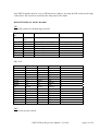
UPPER RS422B
15 way D type socket
This is the secondary control port, for future use.
Pin Function Comment Pin Function Comment
1 GND 10 NC
2 TX- 11 NC
3 RX+ 12 NC
4 GND 13 NC
5NC 14NC
6 GND 15 +5V out See note
7TX+
8RX-
9 GND
UPPER RS232
15 way D type socket
This has both serial control ports. Use this or the RS422A port to control the upper keyer. Use RX1
and TX1 as RX2 and TX2 are for future use only.
Pin Function Comment Pin Function Comment
1 GND 10 NC
2 TX1 11 NC
3 RX1 12 NC
4NC 13NC
5NC 14NC
6 NC 15 +5V out See note
7 TX2 Future use
8 RX2 Future use
9 GND
LOWER REMOTE, LOWER RS422A, LOWER RS422B and LOWER RS232 are connected the
same as the upper controls but for the lower X-KEY module.

X-KEY Effects Keyer User Manual 22/12/98 page 8 of 28
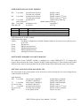
REMOTE CONNECTIONS FOR PAN-XKEY
RS422 (Main control connection)
9 way D type plug
Pin Function Comment
1 GND
2RX-
3TX+
4 GND
5 +5V in Use this or DC power connector
6 GND
7RX+
8TX-
9 GND
RS232
9 way D type plug
Pin Function Comment
1 GND
2RX1
3TX1
4NC
5 +5V in Use this or DC power connector
6NC
7 RX2 Future use only
8 TX2 Future use only
9 GND
REMOTE (Future use only)
9 way D type socket
Pin Function Comment
1 GPI1 Inputs. Active connect to ground
2GPI2
3GPI3
4GPI4
5GPI5
6GPI6
7GPI7
8GPI8
9 GND

X-KEY Effects Keyer User Manual 22/12/98 page 9 of 28
+6VDC INPUT CONNECTOR FOR PAN-XKEY
Latching 3-pin DIN socket for power input.
Use if power not connected via remote cables. Low voltage supply, with IEC mains input and a lead
with the correct plug on is supplied with the control panel.
Pin Function Comment
1 +6V DC Regulated to +5V on CPU
2Gnd
3 No connect
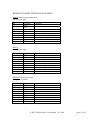
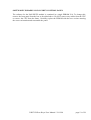
CONTROL CABLE FOR RS422 CONTROL OF A SINGLE X-KEY
15 way D plug for FR1-2XKEY 9 way D socket for PANXKEY
Pin Function Comment Pin Function Comment
1 GND 1 GND
2 TX- 2 RX-
3 RX+ 3 TX+
4 GND 4 GND
6 GND 6 GND
7 TX+ 7 RX+
8 RX- 8 TX-
9 GND 9 GND
15 +5V out See note 5 +5V in Use this or DC power
connector
CONTROL CABLE FOR RS232 CONTROL OF A SINGLE XKEY
15 way D plug for FR1-2XKEY 9 way D socket for PANXKEY
Pin Function Comment Pin Function Comment
1 GND 1 GND
2 TX1 2 RX1
3 RX1 3 TX1
15 +5V out See note 5 +5V in Use this or DC power
connector
CONTROL CABLE FOR RS422 CONTROL OF MULTIPLE X-KEY MODULES
If more than one module is controlled from the same remote control panel, the remote control must
be externally looped through to all the XKEY modules, even if they are in the same frame. (The
upper and lower RS422 connection in a frame are NOT connected together internally.)
The +Vout MUST ONLY BE CONNECTED TO A SINGLE FR1-2XKEY PORT. This should be
the nearest connector to the PANXKEY remote panel. If it is not convenient to take power in this
way, a low voltage supply is supplied with the control panel, and then +5v need not be connected in
the control cable.

X-KEY Effects Keyer User Manual 22/12/98 page 10 of 28
Each XKEY module must be set to a different device address, by using the DIP switch on the edge
of the board. This can be accessed from the front panel of the frame.
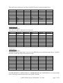
DIP SWITCHES ON X-KEY BOARD
SW1
8 way DIP switch on left-hand edge of board.
Switch
No.
Normally Up Down
S1 Always
Up
Enable system clock Disable system clock
S2 Down Channel A baud = 19200 Channel A baud = 9600
S3 Down Channel B baud = 19200 Channel B baud = 9600
S4 Up Future use
S5 See below Remote address
S6 See below Remote address
S7 See below Remote address
S8 See below Remote address
SW1 S5-8
S8 S7 S6 S5 Remote Address
Down Down Down Down 1
Down Down Down Up 2
Down Down Up Down 3
Down Down Up Up 4
Down Up Down Down 5
Down Up Down Up 6
Down Up Up Down 7
Down Up Up Up 8
Up Down Down Down 9
Up Down Down Up 10
Up Down Up Down 11
Up Down Up Up 12
Up Up Down Down 13
Up Up Down Up 14
Up Up Up Down 15
Up Up Up Up 16
SW2
Unused 8 way piano switch

X-KEY Effects Keyer User Manual 22/12/98 page 11 of 28
LINK POSITIONS ON X-KEY MODULE
JP2 3 way link towards front of board RS422 control
Towards rear of board RS232 control
JP1 3 way link towards front of board RS422 control (2nd port)
Towards rear of board RS232 control (2nd port)
LK7 3 way link towards R197 enable battery back-up
away from R197 disable battery back-up
LK6 2 way link momentary close reset board
LK4 and LK5 See Below 625/525
LK4 LK5 Use
Open Open Force 625 Line operation
Closed Open Force 525 Line operation
Open Closed Auto standard on Analogue Reference Input
LED indication on X-KEY module
LEDs from left to right
Yellow On during configuration of board. Should switch on for about 10 seconds at power-
up or reset.
Green No function
Green SDI key input present
Green SDI background present
Green SDI foreground present
Green Analogue reference syncs present
SOFTWARE UPGRADES ON X-KEY MODULE
The software for the X-KKEY module is contained in a single EPROM IC72. To change this
remove the board from the frame, using the X-KEY board removing tool. This attaches to the board
stiffener at the front of the board between the LEDs and the DIP switch at the centre of the board.
GETTING ACCESS TO THE PAN-XKEY CPU
The front panel of the control panel can be removed by first removing the six screws along the top
of the long face of the box.
Link Positions
LK1 3 way link away from U3 MAX232 disable battery (default)
towards U3 MAX232 enable battery back-up
J3 3 way link away from U3 MAX232 RS422 control (default)
(J3 next to LK1) towardsU3 MAX232 RS232 control
J2 3 way link towards front of board RS422 control (2nd port)
(J2 next to J3) Towards rear of board RS232 control (default)
SW2 8 way piano switch Future use only.

X-KEY Effects Keyer User Manual 22/12/98 page 12 of 28
SOFTWARE UPGRADES ON PAN-XKEY CONTROL PANEL
The software for the PAN-XKEY module is contained in a single EPROM U10. To change this,
remove the front panel from the box as described above. Do NOT remove any cables from the CPU
or remove the CPU from the frame. Carefully replace the EPROM with the new version ensuring
the correct orientation and reassemble the panel.

X-KEY Effects Keyer User Manual 22/12/98 page 13 of 28
OPERATION INSTRUCTIONS
GETTING STARTED
Ensure the system is correctly installed. Each keyer should have analogue syncs connected, a
foreground and a background source, and the main output should be viewed on a picture monitor.
The timing of the input sources should be within 20us of the input reference. At power-up the unit
will take 10 seconds to configure. During this period the video output will be invalid.
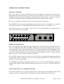
The top row of buttons are quick access keys to the main menus, or functions.
Press REMOTE on the top right of the button area and select remote 1 by pressing F1 to control the
keyer with an address of 1. Pressing REMOTE toggles between keyers 1 to 5 and 6 to 10.
Press MIX on the top row of buttons. Move the T-bar back and forwards to mix between the 2
sources. The system is now working!
MODES OF OPERATION
There are 4 mode buttons, which define the configuration of the keyer and are mutually exclusive.
These are CHROMA, MIX, KEY and WIPE. Selecting one of the buttons initialises the keyer, and
sets some default values. The function buttons F1 to F5, knobs and T bar set the adjustments. There
is an LED next to each knob and two by the T bar to show when they are active. When there are
lower levels of menu control these are selected by the function buttons F1 to F5. The À§ “up menu”
button next to F1 is used to return to higher level menus.
The OUTPUT button on the top menu can be used to look at suppressed foreground and keyed
background in additive Chroma key mode to assist setting these up of the key. The actual key can
also be viewed on the main output.
The MEMORY key allows storing and restoring of up to 10 set ups within the battery backed-up
memory of the X-KEY module. REMOTE allows the selection of 1 of up to 10 X-KEY modules for
control.
USING THE X-KEY AS A CHROMA KEYER
The X-KEY module has a very powerful chroma keyer, which with an understanding of the various
parameters can give excellent results. The following strategy should ensure correct set up.

X-KEY Effects Keyer User Manual 22/12/98 page 14 of 28
1 ADDITIVE CHROMA KEY MODE
Press CHROMA to select chroma key mode. Press F1 for COLOUR and then F5 to select ADD
mode if not already in this mode.
2 DO AN AUTO SETUP
Press CHROMA to select chroma key mode. Press F5 for AUTO and then F2 for CURSOR ON.
Use H POS and V POS on knob 1 and knob 2 to move the cursor to a typical foreground key colour
(blue/green etc). Press GRAB to get an auto set up.
3 CHECK FOREGROUND ADJUSTMENT
Press OUTPUT in the top-level buttons and F2 for foreground to output suppressed foreground.
Press CHROMA once only to allow the output to stay with the suppressed foreground and to access
CHROMA adjustments. Then press F1 for colour adjustments. Adjust the hue on knob 1 and
acceptance angle on knob 2 to get the background colour suppressed. Adjust Y suppression on knob
3 to adjust the background to black instead of grey. The suppression angle will not require much
adjustment. This control may help later to improve the transition between foreground and
background.
4 CHECK BACKGROUND ADJUSTMENT
Press OUTPUT and then F3 KeyBack to output the keyed background. Press CHROMA once to
get back to CHROMA adjustments, then F2 for key adjustments. Adjust gain on knob 2 to get full
amplitude background and lift on knob 1 to remove transparency in the foreground. Lift should be
zero, or slightly negative to get rid of any transparency on black objects. Transparency on white or
light blue foreground objects can be removed by increasing Y correction on knob 3. If transparency
persists then this can be countered by pressing the ˤ UP MENU button, then COLOUR to make
adjustments to the acceptance angle, and the hue. Now press OUTPUT then the F4 key summed to
give the combine output.
5 SHADOW and FORCE
Refer to the instructions for these sections to get shadow background and mask\alpha key force
settings. Note that the key gain and lift can be used to change shadow effects and that studio
lighting is critical. To get shadow to work correctly there must be even lighting on the colour
background so that the reduced lighting of shadow can be used to reduce the gain of the background
without effecting the rest of the background. Shadows work well with additive keying as the
keying colour in the foreground is fully suppressed even when the key is not full amplitude. In
multiplicative keying there will be a blue tinge to the shadow area. Normally, multiplicative keying
should only be used when shadows are not required and when the foreground signal is too poor to
get a good effect with additive keying.

X-KEY Effects Keyer User Manual 22/12/98 page 15 of 28
DETAILED DESCRIPTION OF MENUS
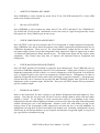
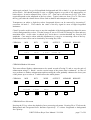
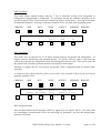
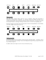
Switch On menu
A welcome message is first displayed. Press one of the top-level keys to start operation. X-KEY
modules will return to last used set-up at power-up.
CHROMA MIX KEY WIPE OUTPUT MEMORY REMOTE
X – K E Y C o n t r o l P a n e l
Software V1.4.2
ˤ F1 F2 F3 F4 F5
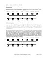
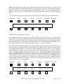
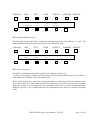
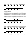
CHROMA Top Menu
Select Colour, Key, Shadow, Force or Auto set-up menus. Select the Auto menu first to get a quick
set-up then use the Colour and Key menus for fine adjustments. The shadow menu allows
enhanced shadow effects in either all, or the lower section of the picture. The force menu allows a
background force mask and a foreground force mask to be created that can be combined with an
external alpha key.
The force menu allows the operator to make use of the key input to create sophisticated foreground
and background masks. This feature can be used with the internal foreground and background
masks. The internal masks can also be prioritised as to which one generates the force when the
masks overlap. This allows more complex shapes to be created. The masks can be used to hide
physical imperfections in a virtual set or permit chroma keying in a limited area only. Also, the
background force can be used to mask out areas of the foreground that should be the chroma keying
colour but are at the edge of the set, or badly lit.
CHROMA MIX KEY WIPE OUTPUT MEMORY REMOTE
1 Chroma-Key Main Menu
Colouro Keyo Shadowo Forceo Autoo
ˤ F1 F2 F3 F4 F5

X-KEY Effects Keyer User Manual 22/12/98 page 16 of 28
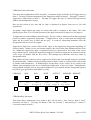
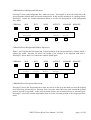
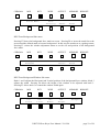
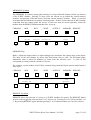
CHROMA/Colour Sub-menu
This menu allows adjustment of Hue on knob 1, Acceptance Angle on knob 2 and Y Suppression on
knob 3. Pressing F4 allows adjustment of the Suppression Angle on knob 3. Pressing F3 returns Y
Suppression control back to knob 3. Pressing F5 toggles the type of Chroma Keying between
additive and multiplicative keying.
Hue sets the colour to key onto and its value is displayed in degrees from zero to 360 with
wraparound.
Acceptance Angle adjusts the range of colours that will be accepted as key-colour. The value
displayed goes from 32 to 255 and represents a hue angle from about 30 degrees to 120 degrees.
Y Suppression is used in additive chroma keying. The key-colour is subtracted from the foreground
picture to produce suppressed foreground. Y Suppression is used to ensure that the background,
where the key colour was, is black and not grey. It works by subtracting luminance from the
foreground in the area of the key signal.
Suppression Angle has a minor effect on the edges of the suppressed foreground depending on
picture content. Adjust it to try and visually improve the effect when other adjustments have been
set. Within the suppression angle, foreground colours are suppressed to the centre of the vector
scope (black or grey). Outside the suppression angle the colours are suppressed in a direction on the
vector scope in parallel with the key colour. This changes the transitions from key colour to
foreground colour.
Both additive keying (with key-colour suppressed to black) and conventional keying are available
for chroma keying. Additive keying normally produces better results as it allows linear effects such
as shadow and transparency. In multiplicative keying there can be a tinge of key-colour to the
shadow and transparent areas due to insufficient suppression of the key colour. Multiplicative
keying should normally only be used when shadows are not required and the foreground signal is
too poor to get a good effect with additive keying.
CHROMA MIX KEY WIPE OUTPUT MEMORY REMOTE
1 333 140 100 50 Add
Hue Accept θ Y Supp Supp θ Key Mode
ˤ F1 F2 F3 F4 F5
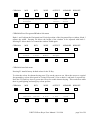
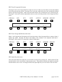
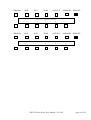
CHROMA/Key Sub-menu
This menu allows adjustments to be made to Key Lift on knob 1, Key Gain on knob 2 and Y
correction on knob 3. Pressing F4 adjusts Clean Up on knob 3 and pressing F3 returns Y
Correction control to knob 3.

X-KEY Effects Keyer User Manual 22/12/98 page 17 of 28
Adjust gain on knob 2 to get full amplitude background and lift on knob 1 to get the foreground
area to black. Lift should normally be zero, or slightly negative to get rid of any transparency on
black objects. It can be adjusted from –128 to +127. Gain can be set from zero to 255. The value
required depends on the amplitude of the key-colour. Typical values are from 35 to 70. The lower
the key gain value the cleaner linear effects such as shadow and transparency will appear.
Transparency on white or light key-colour foreground objects can be removed by increasing Y
correction on knob 3. This reduces the value of the key signal in areas of high foreground
luminance.
Clean-Up can be used in some cases to stop the amplitude of the background being reduced in areas
of noisy background key-colour. This has a range of zero to 255 with 255 having no effect and zero
maximum effect. As the value is reduced, key levels above a certain threshold are forced to full
amplitude. Care must be taken with this adjustment as it can give a contouring effect of the key.
Sometimes a better effect can be obtained by increasing Key Gain.
CHROMA MIX KEY WIPE OUTPUT MEMORY REMOTE
1 -5 50 0 255
Lift Gain Y Corr Clean Up
ˤ F1 F2 F3 F4 F5
CHROMA/Shadow Sub-menu
This menu allows Shadow enhancement to be turned on and off using F1 and to vary the gain of
enhancement using F3. Knob 1 sets the vertical range of the picture that is enhanced. A value of
zero performs no shadow enhancement and increasing the value gradually enhances the lower part
of the picture up to a value of 72 which effects the whole picture.
CHROMA MIX KEY WIPE OUTPUT MEMORY REMOTE
1 Off 50 128 Shadow Menu
On/Off V Pos Gain
ˤ F1 F2 F3 F4 F5
CHROMA/Force Sub-menu
Pressing the F1 key selects the alpha key force processing sub-menu. Pressing F4 or F5 selects the
Background and Foreground force function respectively. F3 selects foreground or background
force priority.

X-KEY Effects Keyer User Manual 22/12/98 page 18 of 28
When a back ground force mask and a foreground mask are both defined and set to on there needs
to be some control over which mask has the most significance when they interact with each other.
When the priority is set to foreground, the foreground mask will over run the background mask.
When the priority is set to background then the background mask will over run the foreground
mask.
If an external alpha key and force masks are enabled they are combined with a non-additive mix.
CHROMA MIX KEY WIPE OUTPUT MEMORY REMOTE
1 Force Menu Fore
α Keyo Priority Backo Foreo
ˤ F1 F2 F3 F4 F5
CHROMA/Force/Alpha Key Sub-menu
The Alpha Key is used to force the key signal in areas that may not be the key-colour in the
foreground. It is an external SDI signal that forces the background into the foreground allowing the
use of three-dimensional objects in the virtual set. By switching this effect on and off people can be
made to walk in front of or behind virtual objects. There are no gain adjustments on this input, so it
must be provided at the correct levels from black to white. It can also be inverted.
ForceFB allows the alpha key input to be used as a background and/or foreground force and can be
turned on and off. ForceFB analyses the key signal on the alpha key input. Firstly, the signal needs
to be within certain bounds. If the signal is below digital black (8-bit value 16) it is clipped to
digital black (8-bit value decimal 16). If the signal is above digital peak white (8-bit value decimal
235) it is clipped to digital peak white (8-bit value 235). Secondly, the signal is split into three
ranges. Background force is extracted from a range of pixel values from 16 to 48 where 16
represents full background force and 48 represents no background force. Foreground force is
extracted from a range of pixel values from 203 to 235 where 235 represents full foreground force
and 203 represents no foreground force. Values between 48 and 203 permit the normal CSO key to
pass through unaffected. In this mode, 128 linear levels of background and foreground force can be
achieved using a single 10-bit alpha key.
CHROMA MIX KEY WIPE OUTPUT MEMORY REMOTE
1 On Off Off Alpha Key Menu
α Key ForceFB Invert
ˤ F1 F2 F3 F4 F5

X-KEY Effects Keyer User Manual 22/12/98 page 19 of 28
CHROMA/Force/Background Sub-menu
Pressing F5 shows the background force mask on screen. Pressing F4 to invert the mask forces the
area around the defined mask to become background. In this way the mask acts as a garbage matte.
Pressing F1 selects the window adjustment menu to set the size and position of the background
force mask.
CHROMA MIX KEY WIPE OUTPUT MEMORY REMOTE
1 Background Force Off Off
Windowo Invert Force
ˤ F1 F2 F3 F4 F5
CHROMA/Force/Background/Window Sub-menu
Knob 1 and 2 adjusts the Horizontal and Vertical position of the background force window. Knob 3
adjusts the width. Pressing F4 allows the height of the window to be adjusted with knob 3.
Pressing F3 allows knob 3 to control the window width again.
CHROMA MIX KEY WIPE OUTPUT MEMORY REMOTE
1 100 100 100 100 Backgnd
H Pos V Pos Width Height
ˤ F1 F2 F3 F4 F5
CHROMA/Force/Foreground Sub-menu
Pressing F5 shows the foreground force mask on screen. In this way the mask prevents the defined
area from being chroma keyed. Pressing F4 to invert the mask forces the area around the defined
mask to become foreground. In this way the mask defines only a limited area to be chroma keyed.
Pressing F1 selects the window adjustment menu to set the size and position of the foreground force
mask.

X-KEY Effects Keyer User Manual 22/12/98 page 20 of 28
CHROMA MIX KEY WIPE OUTPUT MEMORY REMOTE
1 Foreground Force Off Off
Windowo Invert Force
ˤ F1 F2 F3 F4 F5
CHROMA/Force/Foreground/Window Sub-menu
Knob 1 and 2 adjusts the Horizontal and Vertical position of the foreground force window. Knob 3
adjusts the width. Pressing F4 allows the height of the window to be adjusted with knob 3.
Pressing F3 allows knob 3 to control the window width again.
CHROMA MIX KEY WIPE OUTPUT MEMORY REMOTE
1 100 100 100 100 Foregnd
H Pos V Pos Width Height
ˤ F1 F2 F3 F4 F5
CHROMA/Auto Sub-menu
Pressing F1 installs factory default values for the X-Key.
To select the colour for chroma keying press F2 to set the cursor to on. Move the cursor to a typical
foreground key colour (blue/green etc) using H Pos and V Pos on knob 1 and knob 2 respectively.
Press the F5 Grab key once to get an auto set-up for usable chroma keying. This works best when
there is good lighting and strong key colour present.
CHROMA MIX KEY WIPE OUTPUT MEMORY REMOTE
1 On 200 198 Done
Default Cursor H Pos V Pos Grab
ˤ F1 F2 F3 F4 F5
La page charge ...
La page charge ...
La page charge ...
La page charge ...
La page charge ...
La page charge ...
La page charge ...
La page charge ...
-
 1
1
-
 2
2
-
 3
3
-
 4
4
-
 5
5
-
 6
6
-
 7
7
-
 8
8
-
 9
9
-
 10
10
-
 11
11
-
 12
12
-
 13
13
-
 14
14
-
 15
15
-
 16
16
-
 17
17
-
 18
18
-
 19
19
-
 20
20
-
 21
21
-
 22
22
-
 23
23
-
 24
24
-
 25
25
-
 26
26
-
 27
27
-
 28
28


dans d''autres langues
- English: Crystal Vision X-KEY User manual
Autres documents
-
 Blackmagic Design ATEM Mini Manuel utilisateur
-
Blackmagic Ultimatte Manuel utilisateur
-
-
Roland V-1200HD Le manuel du propriétaire
-
-
Analog way CentriX CTX8022 Manuel utilisateur
-
Blackmagic Desktop Video Manuel utilisateur
-
-
-
Sony CCU-M5A Operating Instructions Manual
