SportsArt P759 Le manuel du propriétaire
- Catégorie
- Fitness, gymnastique
- Taper
- Le manuel du propriétaire

1. INTRODUCTION..................................................................................................
2. IMPORTANT SAFETY PRECAUTIONS...............................................................
3. LIST OF PARTS...................................................................................................
4. ASSEMBLING THE PRODUCT
STEP 1 Cover Support Plate and the Connector Installation.............................
STEP 2 Weight Stack Installation.......................................................................
STEP 3 CAM Installation....................................................................................
STEP 4 Cable Installation..................................................................................
STEP 5 Upper Cushion Arm Installation............................................................
STEP 6 Cylindrical Cushion Arm Installation.....................................................
STEP 7 Seat Bottom and Seat Back Installation................................................
STEP 8 Apply the Weight Stack Sticker.............................................................
STEP 9 Front Cover and Rear Cover Installation...............................................
STEP 10 Top Covers Installation ........................................................................
STEP 11 Storage Tray Installation.......................................................................
STEP 12 Cable Adjustment..................................................................................
STEP 13 Stack Fork Inspections.........................................................................
5. OPERATION INSTRUCTION................................................................................
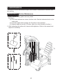
6. MAINTENANCE....................................................................................................
Maintenance Machine Maintenance......................................................................
Maintenance Schedule..........................................................................................
Maintenance Task List...........................................................................................
Maintenance One-Year Maintenance Log.............................................................
7. CONSIGNES DE SECURITE IMPORTANTES.....................................................
1
2
5
8
13
‘ ‘
17
20
24
25
26
28
29
32
33
34
35
36
40
40
41
42
43
44
P759 OWNER’S MANUAL CONTENTS

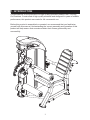
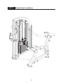
Congratulations on the purchase of a high quality SportsArt product, the P759 Leg
Curl machine. Constructed of high quality materials and designed for years of reliable
performance, this product was made for full commercial use.
Before this product is assembled or operated, we recommend that you familiarize
yourself with this manual. Understanding the correct assembly and operation of this
product will help ensure that exercisers obtain their fitness goals safely and
successfully.
1
1. INTRODUCTION

2
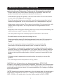
2. IMPORTANT SAFETY PRECAUTIONS
This product was designed and built for optimum safety. However certain precautions
apply during the use of this product. Please note the following safety precautions:
.Please read the entire manual before assembly and operation. Make sure the
product is installed and operated as instructed in this manual.
.Assemble and operate the product on a solid, level surface. Do not use outdoors
or near water, including pools and saunas.
.Check the product before every use. Make sure all parts are assembled, and all
fasteners are tightened. Do not use the product if it is disassembled in any way.
.Wear proper workout clothing. Do not wear loose clothing. Do not wear shoes with
leather soles or high heels. Tie all long hair back. Do not go barefoot on this
product.
.Keep away from moving parts. Moving parts may or may not stop immediately if an
object becomes caught or impedes normal motion.
.Use this product only for its intended purpose as described in this manual.
.Be careful when mounting and dismounting the unit.
.Never operate this product if it has been damaged in any way. If it is not working
properly, or has been dropped or damaged, contact a service technician for
repairs.
.Do not use accessories that are not specifically recommended by the
manufacturer. Such parts might cause injuries or cause the unit to fail.
.This product is not intended for use by persons (including children) with reduced
physical, sensory, or mental capabilities, or by people who are otherwise deficient
in product knowledge or experience. If such people use this product, they should
be given training and be supervised at all times by someone responsible for their
safety.
.Children should be supervised to ensure that they do not play on or near the
product.
.The user weight limit for this product is 227 kg, 500 lb.
CAUTION: If you feel any pain or any abnormal sensations, STOP YOUR
WORKOUT and consult your physician immediately. Work within your recommended
exercise level. DO NOT work to exhaustion. Before beginning any exercise program,
you should consult with your doctor. It is recommended that you undergo a complete
physical examination.
*NOTE: Regarding the decaled resistance on the unit weight stack, the actual weight
being lifted is configured at a ratio of 1:1. Example: If the stack fork is engaged at
60KG (132LB) at the weight stack, the actual pulling weight is 60KG (132LB).
.
.
.
.
.
.
.
.
.
.
.
.
.
.

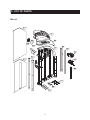
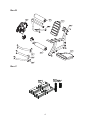
Box A
3
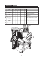
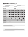
3. LIST OF PARTS

Box B
Box C
4

No. Name Qty
No.
QtyDescription
A1
A2
A3
A4
A5
A6
A7
A8
A9
2
1
1
1
1
1
2
4
Box A - Main Frame Components
A10
A11
A12
A13
A14
A15
A16
A17
5
1
1
1
1
1
1
1
1
1
No. Name Qty
No.
QtyDescription
A20
A21
A22
A23
A24
1
1
1
1
Box B - User Frame Components
A25
A26
A27
A28
A29
1
1
1
1
1
No. Name Qty
No.
QtyDescription
A30
A31
1
Box C - Weight Plates Components
A32
15
1
Weight plate sticker (65kg~100kg/143lb~220lb)
5kg/11lb weight plate
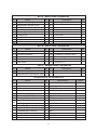
No. Name Qty Notes
Specification
12
13
14
15
16
17
18
19
Components in the Hardware Kit
1
6
8
12
8
10
1
2
2
2
1
1
1
2
1
M6*P1.0*L12
SGN- 07
M6*P1.0*L12
M5*L15
M5* 0. 8* L8
D25
M6* P1. 0* L20
D19* 7. 8
(M4)
(M5)
(M6)
(M8)
(13*17)
Screw soft cap
Phillips screw
Screw socket
Mushroom top inner hex screw
Mushroom top Phillips screw
Mushroom top Phillips screw
Round sticker
Round head inner hex screw
Bushing
L-shaped Allen wrench
L-shaped Allen wrench
L-shaped Allen wrench
L-shaped Allen wrench
Open end wrench
Phillips-head screw driver
Weight stack top right cover
Weight stack top left cover
Main frame
Cover support plate B-2
Cover support plate B-1
Storage tray
Stack fork
Weight stack rod
Cover bracket
Cover support plate A
Cover
Pulley cover
Pulley
Rear cover
Front cover
Bracket
Bracket
CAM
Cylindrical cushion
Upper cushion arm
Seat back
Seat frame
Seat bottom
Cylindrical cushion arm
Connector A
Connector B
Connector C
Weight plate sticker (10kg~60kg/22lb ~132lb)

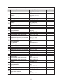
No. Name
Specification
Components on the Product
21
22
23
26
27
29
30
33
34
35
Notes
24
25
28
31
32
38
39
40
41
Hex head screw
Spring washer
Washer
Nylon hex lock nut
Upper stack carriage set
Hex bolt
Washer
PU tube
Nylon hex lock nut
Guide rod
Round head inner hex screw
Spring washer
Washer
Round head inner hex screw
Axle cover
Mushroom top inner hex screw
Mushroom top inner hex screw
Spring washer
Flat washer
CAM stop plate
Mushroom top inner hex screw
Cable set block
Mushroom top inner hex screw
Spring washer
Nylon hex lock nut
Round head inner hex screw
Axle cover
Round head inner hex screw
Round head inner hex screw
Washer
Mushroom top inner hex screw
Spring washer
Washer
Seat back plate
Bevelled head inner hex screw
Nylon hex lock nut
Mushroom top inner hex screw
M10*P1.5*L130
M10
D16*d10.2*t1.0
M10
M8*P1.25*L65
D17*d8.3*t2
∮D12*d8*L51
M8
M8*P1.25*L18
M8*t2.0
D17*d8*t1.5
M8*P1.25*L20
Ø65
M6*P1.0*L20
M6*P1.0*L12
M6
D20*d6.3*t1.5
M6*P1.0*L10
M6*P1.0*L20
M6
M6
M8*P1.25*L20
Ø50
M8*P1.25*L30
M8*P1.25*L15
D28*d8.5*t2
M8*P1.25*L25
M8
D22*d8.2*t2
M8*P1.25*L20
M8
M6*P1.0*L12
6
36
37

7
No. Name
Specification
Components on the Product
44
43
Notes
M6*P1.0*L12
D20*d6.3*t1.5
M5*L8
Mushroom top inner hex screw
Washer
Bevelled head Phillips screw

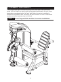
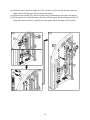
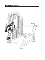
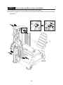
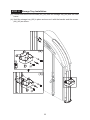
STEP 1 Cover Support Plate and the Connector Installation
8
4. ASSEMBLE THE PRODUCT
Follow instructions below to assemble this product. Note that in this manual the
words “left” and “right” are used to refer to the product and its parts. As such, these
designations correspond to the “left” and “right” sides of a person in position to
exercise on this product. Also, for brevity, the word “screws” or “nuts” is used where
washers and other hardware may be involved.

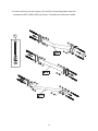
*Loosen and remove the screws (21) and the connecting plates from the
connectors (A27) (A28) (A29) as shown. Carefully set each piece aside.
9

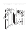
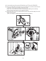
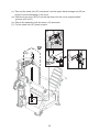
(a). Insert the screw sockets (14) into place in the main frame (A3) as shown, and then use
the screws (15) (16) to secure the brackets (A16) (A17) in place.
(Note: The bracket (A16) must be secured to the top of main frame as shown.)
10
(a)

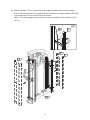
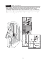
(b). Use the screws (17) to secure the cover support plates (A10) to the straight
frame of the main frame (A3) and then secure the cover support plates (A4) (A5)
to the both side of the curved frame as shown.
(Note: The cover support plates must be secured outside of the bracket (A16)
(A17).)
11
(b)

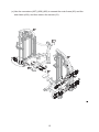
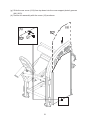
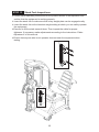
(c).Use the connectors (A27) (A28) (A29) to connect the main frame (A3) and the
seat frame (A24), and then secure the screws (21).
12

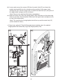
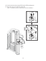
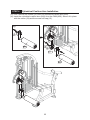
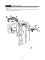
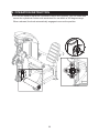
STEP 2 Weight Stack Installation
13

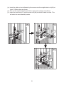
(a).Hold the upper stack carriage set (22), and then cut the zip tie. Gently lower the
upper stack carriage set (22) into place as shown.
(b).Remove the screws (23). Set the guide rod (24) downward into place as shown.
(c).Tilt the guide rod (24) backward, and then lift the upper stack carriage set (22) off
the guide rods as shown. Carefully set the upper stack carriage set (22) aside.
14
(c)
(a)
(b)

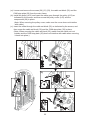
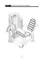
(d). Loosen and remove the screws (25) from the stack fork (A7) and insert the
weight stack rod (A8) into the central mounting position of the upper stack
carriage set (22). Use the screws (25) to secure the stack fork (A7) into place of
the upper stack carriage set (22) as shown.
(Note: Remove the stack fork first before assembling.)
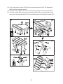
(e). Insert and lower the (5 kg/11lb) weight plates (A30) into place on the guide rods
(24) one at a time. Once complete, slide down the upper stack carriage set (22)
on top of the weight stack.
*If there is an optional (7.5kg/16.5lb) weight plate installed, insert the optional
weight plates first before the (5 kg/11lb) weight plates (A30).
points toward the front.)
(Note: The convex side of weight plate should face up and the stack fork (A7)
15
(e)
(d)

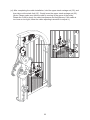
(f).Tilt the guide rods (24) back into place and then lift them up to their mounting
position, and then secure them with the screws (23).
16
(f)

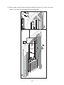
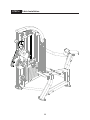
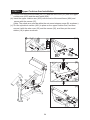
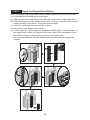
STEP 3 CAM Installation
17

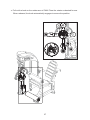
(a). Loosen and remove the screws (26) and the cap (27) from the CAM (A20).
(b). Place the CAM (A20) horizontally into its mounting area, and then rotate the cam
so that the rotator arm is pointing upward as shown.
(Note: Due to the CAM hasn't been connected to the cable yet, to avoid any
injuries, please make sure no one is near the CAM.)
(c). Secure the axle cover (27) in place with the screw (26), and then apply the round
sticker (18) as shown.
(Note: The stopper must be rested above the tube as shown.)
18
(c)
(a)
(b)

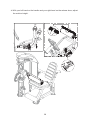
(d). Loosen and remove the screws (28) from the CAM mounting area.
(e). Secure the cover (A11) with the screws (28).
(Note: The bakelite must be rested below the cover as shown.)
19
(e)
(d)
La page est en cours de chargement...
La page est en cours de chargement...
La page est en cours de chargement...
La page est en cours de chargement...
La page est en cours de chargement...
La page est en cours de chargement...
La page est en cours de chargement...
La page est en cours de chargement...
La page est en cours de chargement...
La page est en cours de chargement...
La page est en cours de chargement...
La page est en cours de chargement...
La page est en cours de chargement...
La page est en cours de chargement...
La page est en cours de chargement...
La page est en cours de chargement...
La page est en cours de chargement...
La page est en cours de chargement...
La page est en cours de chargement...
La page est en cours de chargement...
La page est en cours de chargement...
La page est en cours de chargement...
La page est en cours de chargement...
La page est en cours de chargement...
La page est en cours de chargement...
La page est en cours de chargement...
La page est en cours de chargement...
-
 1
1
-
 2
2
-
 3
3
-
 4
4
-
 5
5
-
 6
6
-
 7
7
-
 8
8
-
 9
9
-
 10
10
-
 11
11
-
 12
12
-
 13
13
-
 14
14
-
 15
15
-
 16
16
-
 17
17
-
 18
18
-
 19
19
-
 20
20
-
 21
21
-
 22
22
-
 23
23
-
 24
24
-
 25
25
-
 26
26
-
 27
27
-
 28
28
-
 29
29
-
 30
30
-
 31
31
-
 32
32
-
 33
33
-
 34
34
-
 35
35
-
 36
36
-
 37
37
-
 38
38
-
 39
39
-
 40
40
-
 41
41
-
 42
42
-
 43
43
-
 44
44
-
 45
45
-
 46
46
-
 47
47


SportsArt P759 Le manuel du propriétaire
- Catégorie
- Fitness, gymnastique
- Taper
- Le manuel du propriétaire
dans d''autres langues
- English: SportsArt P759 Owner's manual
Documents connexes
-
SportsArt P733 Le manuel du propriétaire
-
-
-
-
-
-
-
-
-
