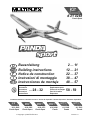
MULTIPLEX Panda Sport Building Instructions
- Catégorie
- Jouets télécommandés
- Taper
- Building Instructions

# 26 4269
Panda
# 26 4268
Panda Sport
Bauanleitung 2 ... 11
Building instructions 12 ... 21
Notice de construction 22 ... 37
Instruzioni di montaggio 38 ... 47
Instrucciones de montaje 48 ... 57
58 - 59
D
F
GB
I
ES
© Copyright by MULTIPLEX 2013 Version 1.0
Ersatzteile
Replacement parts
Pièces de rechanges
Parti di ricambio
Repuestos
Abbildungen
Illustrations
Illustrations
Illnstrazioni
Iiustraciónes
... 28 - 32
# 21 4268
Panda Sport
# 26 4272
Panda Sport
# 1 3268
Panda
# 1 3269
Panda
# 21 4268
Panda Sport
Erhältliche Varianten / Available versions / Version D disponible / Varianti disponibili / Variantes disponibles

2
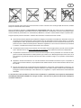
Sicherheitshinweise für MULTIPLEX-Flugmodelle
Das Modell ist KEIN SPIELZEUG im üblichen Sinne.
Mit Inbetriebnahme des Modells erklärt der Betreiber, dass er den Inhalt der Betriebsanleitung, besonders zu Sicher-
heitshinweisen, Wartungsarbeiten, Betriebsbeschränkungen und Mängel kennt und inhaltlich nachvollziehen kann.
Dieses Modell darf nicht von Kindern unter 14 Jahren betrieben werden. Betreiben Minderjährige das Modell unter der
sachkundigen Erwachsenen, ist dieser für die Umsetzung
der Hinweise der BETRIEBSANLEITUNG verantwortlich.
DAS MODELL UND DAZUGEHÖRIGES ZUBEHÖR MUSS VON KINDERN UNTER 3 JAHREN FERNGEHALTEN
WERDEN! ABNEHMBARE KLEINTEILE DES MODELLS KÖNNEN VON KINDERN UNTER 3 JAHREN VERSCHLUCKT
WERDEN. ERSTICKUNGSGEFAHR!
Beim Betrieb des Modells müssen alle Warnhinweise der BETRIEBSANLEITUNG beachtet werden. Die Multiplex Mo-
Betriebes oder Missbrauches dieses Produktes, einschließlich der dazu benötigten Zubehörteile entstehen. Dies beinhaltet
direkte, indirekte, beabsichtigte und unabsichtliche Verluste und Beschädigungen und jede Form von Folgeschäden.
Jeder Sicherheitshinweis dieser Anleitung muss unbedingt befolgt werden und trägt unmittelbar zum sicheren Betrieb
Ihres Modells bei. Benutzen Sie Ihr Modell mit Verstand und Vorsicht, und es wird Ihnen und Ihren Zuschauern viel
Spaß bereiten, ohne eine Gefahr darzustellen. Wenn Sie Ihr Modell nicht verantwortungsbewusst betreiben, kann dies
zu erheblichen Sachbeschädigungen und schwerwiegenden Verletzungen führen. Sie alleine sind dafür verantwortlich,
dass die Betriebsanleitungen befolgt und die Sicherheitshinweise in die Tat umgesetzt werden.
Bestimmungsgemäße Verwendung
Das Modell darf ausschließlich im Hobbybereich verwendet werden. Jede weitere Verwendung darüber hinaus ist nicht
erlaubt. Für Schäden oder Verletzungen an Menschen und Tieren aller Art haftet ausschließlich der Betreiber des Modells
und nicht der Hersteller.
Zum Betrieb des Modells darf nur das von uns empfohlene Zubehör verwendet werden. Die empfohlenen Komponenten
sind erprobt und auf eine sichere Funktion passend zum Modell abgestimmt. Werden andere Komponenten verwendet
oder das Modell verändert, erlöschen alle Ansprüche an den Hersteller bzw. den Vertreiber.
Um das Risiko beim Betrieb des Modells möglichst gering zu halten, beachten Sie folgende Punkte:
zDas Modell wird über eine Funkfernsteuerung gelenkt. Keine Funkfernsteuerung ist sicher vor Funkstörungen.
Solche Störungen können dazu führen, dass Sie zeitweise die Kontrolle über Ihr Modell verlieren. Deshalb müs-
sen Sie beim Betrieb Ihres Modells zur Vermeidung von Kollisionen immer auf große Sicherheitsräume in allen
Richtungen achten. Schon beim kleinsten Anzeichen von Funkstörungen müssen Sie den Betrieb Ihres Modells
einstellen!
zSie dürfen Ihr Modell erst in Betrieb nehmen, nachdem Sie einen kompletten Funktionstest und einen Reichwei-
tentest, gemäß der Anleitung Ihrer Fernsteuerung, erfolgreich ausgeführt haben.
z
nicht geblendet zu werden, oder bei anderen schwierigen Lichtverhältnissen.
z-
ben werden, die das Wahrnehmungs- und Reaktionsvermögen beeinträchtigen.
zFliegen Sie nur bei Wind- und Wetterverhältnissen, bei denen Sie das Modell sicher beherrschen können. Be-
nehmen können.
zFliegen Sie nie an Orten, an denen Sie andere oder sich selbst gefährden können, wie z.B. Wohngebiete, Über-
landleitungen, Straßen und Bahngleise.
z
wirkliches Können, sondern setzt andere Leute nur ein unnötiges Risiko aus. Weisen Sie auch andere Piloten
in unser aller Interesse auf diese Tatsache hin. Fliegen Sie immer so, dass weder Sie noch andere in Gefahr
kommen. Denken Sie immer daran, dass auch die allerbeste Fernsteuerung jederzeit gestört werden kann. Auch
langjährige, unfallfreie Flugpraxis ist keine Garantie für die nächste Flugminute.
D

3
Restrisiken
Auch wenn das Modell vorschriftsmäßig und unter Beachtung aller Sicherheitsaspekten betrieben wird, besteht immer
ein gewisses Restrisiko.
Eine ist daher obligatorisch. Falls Sie in einen Verein oder Verband eintreten, können Sie diese
Sie Modelle und Fernsteuerung immer absolut in Ordnung.
Folgende Gefahren können im Zusammenhang mit der Bauweise und Ausführung des Modells auftreten:
zVerletzungen durch die Luftschraube: Sobald der Akku angeschlossen ist, ist der Bereich um die Luftschraube
freizuhalten. Beachten Sie auch, dass Gegenstände vor der Luftschraube angesaugt werden können oder Ge-
genstände dahinter weggeblasen werden können. Das Modell kann sich in Bewegung setzen. Richten Sie es
daher immer so aus, dass es sich im Falle eines ungewollten Anlaufen des Motors nicht in Richtung anderer
Personen bewegen kann. Bei Einstellarbeiten, bei denen der Motor läuft oder anlaufen kann, muss das Modell
stets von einem Helfer sicher festgehalten werden.
z
und eine entsprechende Versicherung sind unabdingbar.
zAbsturz durch technisches Versagen oder unentdeckten Transport- oder Vorschaden. Die sorgfältige Überprüfung
des Modells vor jedem Flug ist ein Muss. Es muss jedoch immer damit gerechnet werden, dass es zu Material-
zBetriebsgrenzen einhalten. Übermäßig hartes Fliegen schwächt die Struktur und kann entweder zu plötzlichem
Materialversagen führen, oder bei späteren Flügen das Modell aufgrund von „schleichenden“ Folgeschäden
abstürzen lassen.
zFeuergefahr durch Fehlfunktion der Elektronik. Akkus sicher aufbewahren, Sicherheitshinweise der Elektronik-
komponenten im Modell, des Akkus und des Ladegerätes beachten, Elektronik vor Wasser schützen. Auf aus-
reichende Kühlung bei Regler und Akku achten.
Die Anleitungen unserer Produkte dürfen nicht ohne ausdrückliche Erlaubnis der Multiplex Modellsport GmbH
& Co. KG (in schriftlicher Form) - auch nicht auszugsweise in Print- oder elektronischen Medien reproduziert
und / oder veröffentlicht werden.
D

4
Baukasten Panda Sport # 21 4268
Machen Sie sich mit dem Bausatz vertraut!
MULTIPLEX - Modellbaukästen unterliegen während der Produktion einer ständigen Materialkontrolle. Wir hoffen, dass
vor Verwendung zu prüfen,
da bearbeitete Teile vom Umtausch ausgeschlossen sind. Sollte ein Bauteil einmal nicht in Ordnung sein, sind wir nach
Überprüfung gern zur Nachbesserung oder zum Umtausch bereit. Senden Sie das Teil, bitte ausreichend frankiert, an
-
beiten ständig an der technischen Weiterentwicklung unserer Modelle. Änderungen des Baukasteninhalts in Form, Maß,
Technik, Material und Ausstattung behalten wir uns jederzeit und ohne Ankündigung vor. Bitte haben Sie Verständnis
dafür, dass aus Angaben und Abbildungen dieser Anleitung keine Ansprüche abgeleitet werden können.
Achtung!
Ferngesteuerte Modelle, insbesondere Flugmodelle, sind kein Spielzeug im üblichen Sinne. Ihr Bau und Betrieb
erfordert technisches Verständnis, ein Mindestmaß an handwerklicher Sorgfalt sowie Disziplin und Sicherheits-
bewusstsein.
Fehler und Nachlässigkeiten beim Bau und Betrieb können Personen- und Sachschäden zur Folge haben. Da der
diese Gefahren hin.
Wichtiger Hinweis
Verlust des Modells führen. Beachten Sie: In solchen Fällen gibt es von uns keinen Ersatz. Tasten Sie sich also vorsichtig
an die Grenzen heran. Das Modell ist auf den von uns empfohlenen Antrieb ausgelegt, kann aber nur einwandfrei gebaut
und unbeschädigt den Belastungen standhalten. Weitere Tuningmaßnahmen setzen Sachverstand und entsprechend
sinnvolle Maßnahmen zur weiteren Verstärkung voraus.
Fernsteuerelemente im Modell / sonstiges Zubehör
Empfohlene Ausrüstung:
MULTIPLEX Empfänger ab RX-5 light M-LINK Best. Nr. 5 5808
oder
Empfänger RX-5 M-LINK telemetriefähig Best. Nr. 5 5817
Damit können Sie auch die Telemetrie-Module verwenden und Ihr Modell beispielsweise
Servos
6 5120
oder
6 5119
Antriebssatz mit passendem Antriebsakku:
Antriebsatz „Panda Sport“ Li-BATT powered Best. Nr. 33 3662
mit Brushless-Motor PERMAX BL-O 2812-1100,
Regler MULTIcont BL-20 SD,
Antriebssatz:
Antriebsatz „Panda Sport“ Best. Nr. 33 2662
mit Brushless-Motor PERMAX BL-O 2812-1100,
Regler MULTIcont BL-20 SD,
Akkuempfehlung:
15 7321
Klebstoff:
Zacki ELAPOR ® 20g Best.-Nr. 59 2727
Zacki ELAPOR ® Super liquid 10g Best.-Nr. 59 2728
Ladegerät: Best.-Nr. 9 2545
Combo MULTIcharger LN-3008 EQU mit Netzgerät AC/DC 230V/12V 5,0A
Werkzeuge: Klingenmesser, div. Schlitz- und Kreuzschlitz-Schraubendreher, Steck- oder Gabelschlüssel SW10
Model Service Box 8 5500
D

5
Wichtiger Hinweis
Dieses Modell ist nicht aus Styropor ™! Daher sind Verklebungen mit Weißleim, Polyurethan oder Epoxy nicht möglich.
-
angepasste Sekundenkleber. Bei Verwendung von Zacki-ELAPOR® können Sie auf Kicker oder Aktivator weitgehend
verzichten. Wenn Sie jedoch andere Kleber verwenden, und auf Kicker/Aktivator nicht verzichten können, sprühen Sie
aus gesundheitlichen Gründen nur im Freien. Vorsicht beim Arbeiten mit allen Cyanacrylatklebern. Diese Kleber härten
u.U. in Sekunden, daher nicht mit den Fingern und anderen Körperteilen in Verbindung bringen. Zum Schutz der Augen
unbedingt Schutzbrille tragen! Von Kindern fernhalten! An einigen Stellen ist es auch möglich Heißkleber zu verwenden.
Wir weisen in der Anleitung ggf. darauf hin!
Arbeiten mit Zacki ELAPOR®
Zacki ELAPOR® wurde speziell für die Verklebung für unsere Schaummodelle aus ELAPOR® entwickelt.
Um die Verklebung möglichst optimal zu gestalten, sollten Sie folgende Punkte beachten:
dann weitgehend verzichtet werden. Dazu die dem Kleber gegenüberliegende Fläche mit einem feuchten Tuch oder
Schwamm ganz dünn benetzen.
Krumm - gibt es eigentlich nicht. Falls mal etwas z.B. beim Transport verbogen wurde, kann es wieder gerichtet
werden. Dabei verhält sich ELAPOR® ähnlich wie Metall. Etwas überbiegen, das Material federt ein Stück zurück
und behält dann aber die Form. Alles hat natürlich auch seine Grenzen - übertreiben Sie also nicht!
Krumm - gibt es schon!
ab, so als wollten Sie das Modell putzen. Die Lackschichten dürfen keinesfalls zu dick oder ungleichmäßig aufgetragen
werden, sonst verzieht sich das Modell. Es wird krumm, schwer und oft sogar unbrauchbar! Mattlacke bringen optisch
das beste Ergebnis.
Technische Daten: Panda Panda Sport
Spannweite 1160 mm 1160 mm
Länge über alles 800 mm 800 mm
Flächeninhalt
Flächenbelastung
RC-Funktionen:
Höhenruder, Seitenruder, Motorsteuerung
Der Schwerpunkt 55 mmDie Position ist mit kleinen Warzen auf der
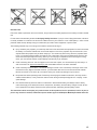
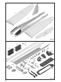
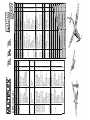
Hinweis: Bildseiten aus der Mitte der Bauanleitung heraustrennen!
1. Vor dem Bau
Prüfen Sie vor Baubeginn den Inhalt Ihres Baukastens.
Dazu sind die Abb. 1+2 und die Stückliste hilfreich.
2. Höhen- und Seitenruderservo vorbereiten
Die Servos mit einem Servotester / MULTImate oder der
Fernsteuerung in Neutralstellung bringen (Trimmung nicht
Servohebel mit Abtriebsbohrung Ø 1mm so montieren,
dass bei beiden Servos der Hebel 90° nach links zeigt.
Die Gestänge werden später in das erste Loch von innen
Arme und der Überstand werden mit einem Seitenschnei-
der abgeschnitten!
Abb. 03
Hinweis: Bei einigen Servohebeln ist die Verzahnung so
aufgeteilt. dass eine Feinjustierung möglich ist. Wenn der
Hebel also nicht genau 90° aufgesteckt werden kann, die-
sen dann um 180° gedreht montieren!
3. Servo im Servorahmen montieren
Das Servokabel durch den Servorahmen 43 stecken und
das Servo an den beiden Arretierlaschen einrasten.
Abb. 03
4. Servos in die Rumpfhälften kleben
An den Servorahmen 43 aussen Kleber anbringen und mit
den Servos in die Rumpfhälften kleben.
4 den Servo-
hebel nach hinten
und bei der linken Rumpfhälfte 3 nach

6
vorne positionieren.
Die Kabel in der Vertiefung nach vorne verlegen und gleich
später beim Verkleben der beiden Rumpfhälften nicht be-
hindern.
Abb. 04+05
5. Bowdenzüge vorbereiten
Die Bowdenzugrohre haben folgende Länge - ggf. kürzen:
Bowdenzugrohr HR Höhenruder 63 Ø2/1 x 470 mm
Bowdenzugrohr SR Seitenruder 64 Ø2/1 x 500 mm
Hinweis: Zum Kürzen der Bowdenzugrohre das Klingen-
messer auf dem Bowdenzugrohr abrollen und dabei an-
ritzen. An dieser Stelle abbrechen - die Schnittkante ist
dann nicht gequetscht und der Stahldraht bewegt sich
leichtgängig!
6. Stahldrähte vorbereiten
Die Stahldrähte haben folgende Länge - ggf. kürzen:
Stahldraht HR Höhenruder 61 Ø1 x 535 mm
Stahldraht SR Seitenruder 62 Ø1 x 565 mm
Nun Draht 61 in Rohr 63 stecken - jeweils die langen Teile.
Ebenso Draht 62 in Rohr 64 stecken - jeweils die kurzen.
7. Bowdenzüge im Rumpf verlegen
In der rechten Rumpfhälfte 4 den langen Draht 62 für
das Seitenruder mit der Z-Biegung im rechten Servohe-
bel einhängen. Draht und Bowdenzugrohr soweit biegen,
dass es am Rumpfende durch die Durchführung gescho-
ben werden kann. Das Rohr so positionieren dass es am
Schaumsteg direkt hinter dem Servo beginnt. Das Rohr
es nicht herausfällt. Das Verkleben erfolgt später zusam-
men mit dem Aluminium 4-kt. Rohr.
Abb. 06
In der linken Rumpfhälfte 3 den kürzeren Draht 61 im Ser-
vohebel einhängen. Hier das Bowdenzugrohr so positio-
nieren, dass es am Rumpfende dort endet, wo sich die
Führung zur Hebelkammer des HLW-Hebels aufweitet.
Abb. 07
8. Rumpf-Verstärkungsrohr einbauen
Das 4-kt. Aluminium Rumpf-Verstärkungsrohr 65
geradlinig und vollständig in die Aussparung in die rech-
te Rumpfhälfte 4 einkleben. Von hinten an der unteren
Rumpfkante entlangpeilen und sicherstellen dass der
Rumpf gerade ist.
Abb. 06
9. Rumpfhälften miteinander verkleben
Halten Sie die beiden Rumpfhälften 3+4 zunächst ohne
Klebstoff zusammen und prüfen Sie deren Passung. Erst
wenn alles exakt passt, werden die beiden Rumpfhälften
miteinander verklebt.
am Aluminium Verstärkungsrohr 65 Klebstoff auftragen.
Dabei zu den Aussenkanten ca. 5mm einhalten, damit der
Klebstoff nicht nach aussen überquillt. Die Teile fügen und
geradlinig ausrichten. Bis zur Aushärtung ggf. mit einigen
Klebestreifen sichern. Von hinten an der unteren Rumpf-
naht entlangpeilen und sicherstellen dass der Rumpf ge-
rade ist und bleibt. Abb. 08
Hinweis: Sicher ist Ihnen aufgefallen, dass die Servoka-
bel der Servos nun eingesperrt sind. Normalerweise wer-
den Sie die Servos nicht mehr wechseln müssen, falls es
doch einmal einen Defekt geben sollte, können Sie den
Schaumsteg zwischen den Servos herausschneiden und
nach dem Servowechsel wieder einkleben.
10. Motor in der Rumpfverkleidung befestigen
Mit dem Brushless Antriebssatz Panda Sport # 33 3662
incl. Akku ist das Modell bestens motorisiert.
Die Komponenten in diesem Antriebssatz sind aufeinan-
der abgestimmt und erprobt. Falls Sie andere Akkus, Reg-
ler, Motore oder Fernsteuerkomponenten einsetzen, liegt
dies in Ihrem Ermessen. Ein Support von unserer Seite ist
dann jedoch nicht möglich.
In die Rumpfverkleidung / Motorspant 42.1 den Elektromo-
tor PERMAX BL-O 2812-1100 mit zwei der im Antriebs-
satz beiliegenden Schrauben M3x6mm und den Unterleg-
scheiben so befestigen, dass die Anschlusskabel auf der
Rumpfunterseite verlegt werden können.
Abb. 09
11. Rumpfverkleidung in den Rumpf kleben
Die Rumpfverkleidung 42.1 mit montiertem Motor passge-
nau vorne auf den Rumpf halten und zentriert ausrichten.
Am Besten lässt sich die mittige Ausrichtung kontrollie-
ren wenn Sie den Rumpf von unten betrachten und sich
an der dahinterliegenden Rumpfaussparung orientieren.
Wenn alles passt, diesen vollständig aufgesteckt mit dem
Schaumteil verkleben. Diese Verklebung vollständig aus-
härten lassen - in der Zwischenzeit werden die Luftschrau-
benblätter am Propellermitnehmer montieren.
Abb. 10
12. Klapp-Luftschraubenblätter montieren
Schrauben Sie zunächst die Klappluftschraubenblät-
85 mit den Zylinderschrauben 84
und den M3 Stoppmuttern 83 an den Propellermitnehmer
80. Ziehen Sie die Schrauben so weit fest, dass die Luft-
schraubenblätter kein Spiel aufweisen, sich jedoch noch
leicht anklappen lassen.
Abb. 11
13. Rumpfrahmen im Rumpf einbauen
Den Rumpfrahmen 40.1
schmalen Stegen etwas zusammendrücken und noch
ohne Klebstoff unten im Rumpf einpassen. Die Stege voll-
ständig an die Schaumteil-Seitenwand und in die einge-
formte Nut drücken und den Rumpfdeckel 41.1 einrasten.
Wenn alles passt diesen Vorgang mit Klebstoff wiederho-
len. Zum Aushärten auf jeden Fall den Rumpfdeckel wie-
der einrasten, damit bis zur Aushärtung alles richtig posi-
tioniert ist.
Abb. 12
Hinweis: Durch Toleranzen bei der Fertigung kann es zur
besseren Optik notwendig sein, im hinteren Bereich des
Rumpfrahmens den Schaum minimal nachzuschneiden.
14. Fernsteuerungseinbau
Mit der Positionierung der Komponenten können Sie die
-
lastkugeln in die Löcher im Seitenleitwerk.

7
Den Regler MULTIcont BL-20 SD an den Anschlüssen
des Motors anstecken und ganz oben im Rumpf mit Klett-
band 20+21 befestigen. Der M-LINK
im Freiraum hinter den Servos auf dem Rumpfboden be-
festigt. Die Antenne wird aus der Abluftöffnung geführt und
Antriebsakku Li-BATT FX 3/1-950 mit Klettband an der
Rumpfseitenwand befestigt. Die Kabel etwas ordnen und
z.B. mit Heisskleber oder Klebeband an der Rumpfwand
festlegen.
Abb. 13
Hinweis: Da die Klettkraft des Klettbandes besser als der
wir das Klettband zusätzlich mit Heisskleber oder Zacki
ELAPOR ® festzukleben.
15. Erster Probelauf des Motors
Hinweis: Den Verbindungsstecker Antriebsakku / Regler-
erst einstecken, wenn Ihr Sender eingeschaltet ist und Sie
sicher sind, dass das Bedienelement für die Motorsteue-
rung auf „AUS“ steht!
In Verbindung mit Ihrer Fernsteuerung und dem An-
-
fen. In Flugrichtung gesehen, muss sich die Antriebswelle
Fall, vertauschen Sie zwei der drei Motoranschlusskabel.
16. Luftschraube und Spinner am Modell montieren
In den Propellermitnehmer 80 den Mitnehmer mit Spann-
konus 82 einstecken. U-Scheibe 87, Zahnscheibe 88 und
Mutter 86 lose auf dem Gewinde montieren.
Abb. 11
Schieben Sie dann den gesamten Zusammenbau auf die
Motorwelle und achten Sie darauf, dass der Propellermit-
nehmer 80 ca. 1 mm Abstand zum Rumpf hat.
Die Mutter festziehen und sicherstellen, dass sich der Ab-
stand beim Anziehen zwischen Propellermitnehmer und
Rumpf nicht verändert! Der Spinner 81 wird mit den bei-
den Schrauben 74 2,2 x 6,5 mm befestigt.
Abb. 14
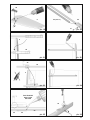
17. Höhenleitwerkshebel vormontieren
Den Gestängeanschluss 25 durch die Bohrung des HLW-
Hebels 50
26 und Mutter 27 befestigen. Die Mutter nur mit den Fin-
gern leicht aufschrauben (der Gestängeanschluß muss
-
ren Gewindestummel mit Schraubensicherung oder Kleb-
stoff sichern. Den Inbus-Gewindestift 24 von der Stirnseite
mit dem Inbusschlüssel 28 in den Gestängeanschluss ein-
schrauben.
Abb. 15
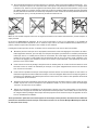
18. Seitenleitwerk fertigstellen
Am Seitenleitwerk 9 das Seitenruder durch mehrmaliges
hin- und herbiegen leichtgängig machen. Das „HLW-La-
gergehäuse“ 46 in die Ausformung ins Seitenleitwerk kle-
ben. Abb. 16
Hinweis: Achten Sie darauf, dass kein Klebstoff in die
-
19. Ruderhorn für Seitenruder
In das „Ruderhorn Twin“ 22 den Kardanbolzen 23 einclip-
sen. Den Inbus-Gewindestift 24 in den Kardanbolzen ein-
drehen. Ruderhorn nach vorne gekippt in die Ausformung
des Seitenruders kleben.
Abb. 17
20. Fertigstellen des Höhenleitwerks
In die linke Höhenleitwerkshälfte 7 die „HLW Steckung mit
der Achse“ 48 einkleben. Abb. 18
In die rechte Höhenleitwerkshälfte 8 die „HLW Steckung
mit Arretierung“ 49 einkleben und hier nur soviel Klebstoff
auftragen, dass dieser nicht nach innen läuft.
Abb. 19
Hinweis: Vor dem Zusammenstecken der Leitwerke die
Klebungen solange aushärten lassen, bis der Kleber si-
cher getrocknet ist - sonst bekommen Sie das Leitwerk
u.U. nicht mehr auseinander!
Zur Demontage drücken Sie auf die mit „X“ gekennzeich-
nete Stelle am Leitwerk 8 um die Arretierung zu lösen.
Abb. 19
21. Vorbereitung der Holmrohre
Den Holmverbinder 44 mit wenig Klebstoff bis zum An-
schlag auf das Aluminium Holmrohr 60
In die seitliche Bohrung im Holmverbinder die Blech-
Linsenschraube 31 ansetzen und mit einen passenden
kräftigem Druck bis zum Anschlag eindrehen. Ggf. kann
das Aluminium auch mit Ø1,5mm vorgebohrt werden. Die
Einbaurichtung des Holmverbinders ist egal, da das Teil
symmetrisch ist.
Abb. 20
6, in die Aussparung für den
auftragen. Das Holmrohr mit dem Holmverbinder vollstän-
dig und passgenau eindrücken.
Abb. 21+22
5 das Holmrohr 60 mit lose aufge-
steckter Flächenarretierung 45 entsprechend in den Flü-
gel kleben. Darauf achten, dass die Flächenarretierung 45
noch nicht mit dem Holm bzw. dem Schaum verklebt wird
sondern sich noch leicht verschieben lässt.
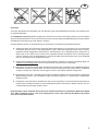
Die Flächenarretierung 45 wird erst nach dem zusammen-
Position am Holm verklebt.
Abb. 23+24
Das Modell dabei auf den Rücken legen und bei vollstän-
Flächenarretierung 45 so in der Verzahnung einrasten,
dass noch ein Spalt zwischen den beiden Kunststoff-
nur an der im Bild gezeigten Position sparsam Zacki ELA-
POR Super liquid
erster Aushärtung das Modell auseinanderbauen und die
Flächenarretierung ggf. nachkleben. Zur Demontage der

8
Flügelvorderkante ziehen, bis die Verzahnung geöffnet ist.
Abb. 25
Hinweis: Wird später beim Betrieb des Modells die Ar-
-
sammendrücken um einen Zahn wieder ein sicherer Halt
erfolgen.
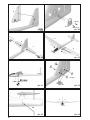
24. Höhenleitwerkshebel im Rumpf einbauen
Den Höhenruder-Servohebel nach vorne drehen um hin-
ten am Stahldraht etwas Freiraum zu schaffen. Nun hinten
den um 90° gedrehten HLW-Hebel 50 in die Aussparung
stecken und erneut um 90° drehen und dabei den Stahl-
draht in den Gestängeanschluss 25 einfädeln. Dann vorne
den Servohebel wieder in Neutralstellung bringen und den
Gestängeanschluss mit dem Inbusschlüssel durch das
seitliche Loch im Rumpf festklemmen.
Abb. 26
25. Seitenleitwerk auf den Rumpf kleben
Das Seitenleitwerk 9 zunächst ohne Klebstoff auf dem
Rumpf anpassen. Die Zapfen des Leitwerks schräg in den
Rumpf stecken, das Leitwerk kippen und den aus dem
Rumpf hervorstehenden Hebel im Lagergehäuse 46 posi-
tionieren. Wenn alles passt diesen Schritt mit Zacki ELA-
POR wiederholen und das Leitwerk sorgfältig zum Rumpf
ausrichten.
Abb. 27
Hinweis:
Zum Ausrichten des Seitenleitwerks empfehlen wir die
kann von vorne gepeilt das Leitwerk entsprechend ausge-
richtet werden.
Abb. 34
26. HLW-Hebel im Lagergehäuse montieren
Nun in das Lagergehäuse 46 den HLW-Hebel 50 einset-
zen. Das Gehäuse mit dem Deckel 47 und den Schrauben
29 M2x10mm verschließen. Leichtgängigkeit prüfen und
ggf. nacharbeiten.
Abb. 28
Nun das Höhenleitwerk probeweise am Rumpf montieren.
Schieben Sie dazu die beiden Höhenleitwerkshälften so
weit zusammen dass diese verriegeln.
Abb. 29
Hinweis: Achten Sie darauf, dass sich das Leitwerk leicht-
gängig bewegen lässt. Ggf. kann es notwendig sein den
Schaum an der Stirnseite der Leitwerke geringfügig zu-
sammenzudrücken. Dies funktioniert am einfachsten wenn
Sie die Leitwerkshälfte mit der Stirnseite auf die Tischkan-
te stellen und unter mässigem Druck hin und herschieben.
Der Schaum kann auch mit dem Messer minimal nachge-
schnitten werden.
27. Kontrolle des Modells
Vergewissern Sie sich, dass das Modell gerade ist und alle
Fernsteuerungskomponenten richtig eingebaut und ange-
schlossen sind. Prüfen Sie Rudereinstellungen, Drehrich-
tungen der Servos und Freigängigkeit der Rudermechani-
ken. Achten Sie darauf, dass die Anschlusskabel nicht in
den sich drehenden Motor bzw. Servohebel gelangen kön-
Motordrehrichtung jetzt zusammen mit dem Propeller.
Abb. 30 + 34
28. Ruderausschläge einstellen (Richtwerte!)
Um eine ausgewogene Steuerfolgsamkeit des Modells zu
erzielen, ist die Größe der Ruderausschläge richtig einzu-
stellen. Die Ausschläge werden jeweils an der tiefsten Stelle
der Ruder gemessen.
Höhenruder: 10 / 10 mm +/-
Seitenruder: 15 / 15 mm +/-
Das Höhenleitwerk steht neutral, wenn durch die seitliche
Öffnung im Rumpf der Inbus-Gewindestift zu sehen ist.
Bevor Sie hier den Gewindestift anziehen stellen Sie das
Höhenruderservo genau auf Neutral!
Abb. 33
29. Dekor anbringen
Dem Bausatz liegt ein Dekorbogen 2.2 bei. Die einzelnen
Schriftzüge und Embleme sind bereits ausgeschnitten und
eigenen Vorstellungen aufgeklebt.
Achtung: Die runden Punkte werden später nach dem
Auswiegen des Schwerpunkts zum Verschliessen der Bal-
lastkammern benötigt - diese also nicht wegwerfen!
Für die eigene farbliche Gestaltung empfehlen wir unser
-
30. Kabinenhaube einfärben
Die Kabinenhaube wird entweder mit einem wasserfesten
Filzschreiber bis zum Rand geschwärzt oder abgeklebt
-
timent lackiert.
Tipps zur Lackierung mit „ELAPOR® Color“ Sprühfarben
31. Schwerpunkt auswiegen
Mit der Position des Reglers, Flugakkus und ggf. etwas
Zusatzballast wird der Schwerpunkt eingestellt. Dieser
liegt 55 mm von der “Flügelnase” am Rumpf nach hin-
ten gemessen. Die Position ist mit kleinen Warzen auf der
-
terstützt das Modell so auspendeln, dass die Rumpfnase
ganz leicht nach unten zeigt.
Der Zusatzballast 30 wird in die Kammern eingefüllt und
mit den runden Aufklebern vom Dekorbogen abgedeckt.
Abb. 32
Tag ab. Besonders günstig sind oft die Abendstunden.
-
chen Sie sich einen geübten Helfer. Ganz allein geht es
Ihren Händler befragen.
Vor dem ersten Flug unbedingt einen Reichweitentest
durchführen! Halten Sie sich dabei an die Vorgaben des
Herstellers Ihrer Fernsteuerung!
Sender- und Flugakku sind frisch und vorschriftsmäßig
geladen. Vor dem Einschalten des Senders sicherstellen,

9
dass der verwendete Kanal frei ist, sofern keine 2,4 GHz-
Anlage verwendet wird.
Falls etwas unklar ist, sollte auf keinen Fall ein Start erfol-
gen. Geben Sie die gesamte Anlage (mit Akku, Schalterka-
zur Überprüfung.
Das Modell wird aus der Hand mit laufendem Motor gestar-
Machen Sie sich in ausreichender Höhe vertraut, wie das
Modell reagiert, wenn der Motor ausgeschaltet ist. Trimmen
gleichmässige Fluggeschwindigkeit beibehält.
-
der Höhe, so sind Sie vorbereitet, wenn der Antriebsakku
leer wird.
Versuchen Sie in der Anfangsphase, insbesondere bei der
Landung, keine „Gewaltkurven“ dicht über dem Boden.
Landen Sie sicher und nehmen besser ein paar Schritte
in Kauf, als mit Ihrem Modell bei der Landung einen Bruch
zu riskieren.
34. Flug am Hang
-
mit zu den schönsten Erlebnissen. Die Krönung ist das
-
hochkreisen bis an die Sichtgrenze (Vorsicht das Modell
-
Vollendung. Durch den Elektroantrieb kann das Modell bei
werden. Das Risiko das Modell bei einer Aussenlandung
im Tal zu beschädigen ist somit nicht gegeben.
35. Lehrer / Schüler Betrieb
Der Panda / Panda Sport ist aufgrund seiner gutmütigen
Flugeigenschaften und der langen Flugzeit auch ideal als
Lehrer-Schüler Stick # 4 5183, zwei MULTIPLEX Sendern
und einem geübten Lehrer kann der Schüler das Fliegen
materialschonend erlernen. Nach kurzer Zeit wird der
Schüler das Modell selbstständig steuern können.
Als Schüler-Sender können alle Sender mit 2,4 GHz M-
LINK Technologie verwendet werden. Als Lehrer-Sender
eignen sich alle MULTIPLEX-Sender mit DIN-Multifunk-
tionsbuchse und Lehrer-Funktionalität, gleichgültig ob
2,4 GHz M-LINK*- oder xx MHz-Ausrüstung. Lehrer und
Schüler können bei Bedarf auch 20 – 30 Meter voneinan-
der entfernt stehen und es gibt keine Behinderung wegen
des Verbindungskabels mehr.
36. Sicherheit
Sicherheit ist das oberste Gebot beim Fliegen mit Flug-
Falls Sie in einen Verein oder Verband eintreten, können
Sie diese Versicherung dort abschließen. Achten Sie auf
absolut in Ordnung. Informieren Sie sich über die Lade-
technik für die von Ihnen verwendeten Akkus. Benutzen
Sie alle sinnvollen Sicherheitseinrichtungen, die angeboten
werden. Informieren Sie sich in unserem Hauptkatalog oder
auf unserer Homepage www.multiplexrc.de
aus der Praxis für die Praxis gemacht. Fliegen Sie verant-
wortungsbewusst! Anderen Leuten dicht über die Köpfe zu
Könner hat dies nicht nötig. Weisen Sie auch andere Piloten
in unser aller Interesse auf diese Tatsache hin. Fliegen Sie
immer so, dass weder Sie noch andere in Gefahr kommen.
Denken Sie immer daran, dass auch die allerbeste Fern-
kann. Auch langjährige, unfallfreie Flugpraxis ist keine
Garantie für die nächste Flugminute.
Prüfen Sie vor jedem Start den sicheren Sitz des Akkus,
der Flügel und Leitwerke. Kontrollieren Sie auch die
Funktion aller Ruder!
Wir, das MULTIPLEX -Team, wünschen Ihnen beim Bauen
und später beim Fliegen viel Freude und Erfolg.
MULTIPLEX Modellsport GmbH & Co. KG

10
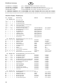
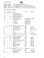
Erhältliche Varianten
# 21 4268 KIT Panda Sport Baukasten
# 26 4268 RR Panda Sport Fertigmodell, Servos, Regler, Motor BL-O 2812-1100
# * 26 4272 *RR+ Panda Sport Fertigmodell, Servos, Regler, Motor BL-O 2812-1100, Empfänger, Akku
# 26 4269 RR+ Panda Fertigmodell, Servos, Regler / Empfänger, Motor 400 6V, Akku
# 1 3268 RTF Panda Mode 1 und 3 Fertigm. Servos, Regler / Empfänger, Motor 400 6V, Sender, Akku, Ladegerät
# 1 3269 RTF Panda Mode 2 und 4 Fertigm. Servos, Regler / Empfänger, Motor 400 6V, Sender, Akku, Ladegerät
Mit einem farbigen Textmarker können Sie sich zur besseren Übersicht ihre Variante in der untenstehenden Stückliste markieren
!
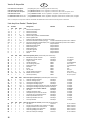
Stückliste Panda / *Panda Sport
Lfd. Stückzahl Bezeichnung Material Abmessungen
KIT RR RR+ RTF
1 1 1 1 1 Bauanleitung KIT
1.1 0 1 0 0 Zusatzanleitung RR
1.2 0 0 1 0 Zusatzanleitung RR+
1.3 0 0 0 1 Zusatzanleitung RTF
1.4 0 1 *1/0 0 Anleitung Antriebssatz "Panda SPORT"
1.5 0 1 *1/0 0 Anleitung BL-Regler
1.7 1 1 1 1 Reklamationsbearbeitung Modelle
2.1
2.2
3 1 1 1 1 Rumpfhälfte links Elapor geschäumt
4 1 1 1 1 Rumpfhälfte rechts Elapor geschäumt
5
6
7 1 1 1 1 Höhenleitwerk links Elapor geschäumt
8 1 1 1 1 Höhenleitwerk rechts Elapor geschäumt
9 1 1 1 1 Seitenleitwerk Elapor geschäumt
KIT RR RR+ RTF Kleinteilesatz
20 3 3 3 3 Klettband Pilzkopf Kunststoff 25 x 60mm
21 3 3 3 3 Klettband Velours Kunststoff 25 x 60mm
22 1 1 1 1 Ruderhorn "Twin" Kunststoff Fertigteil
23 1 1 1 1 Kardanbolzen Metall Fertigteil Ø6mm
24 2 2 2 2 Inbus-Gewindestift Metall M3 x 3mm
25 1 1 1 1 Gestängeanschluß Metall Fertigteil Ø6mm
26 1 1 1 1 U-Scheibe Metall M2
27 1 1 1 1 Mutter Metall M2
28 1 1 1 1 Inbusschlüssel Metall SW 1,5
29
30 50 50 50 50 Trimmgewicht Metallkugel Ø 4mm / ca.15g
31
KIT RR RR+ RTF Kunststoffteilesatz
40
40.1
41
41.1
42
42.1
43 2 2 2 2 Servorahmen "Nano" stehend Kunststoff Fertigteil
44 1 1 1 1 Holmverbinder Kunststoff Fertigteil
45 1 1 1 1 Flächenarretierung Kunststoff Fertigteil
46 1 1 1 1 HLW Lagergehäuse Kunststoff Fertigteil
47 1 1 1 1 HLW Lagerdeckel Kunststoff Fertigteil
48 1 1 1 1 HLW Steckung mit Achse Kunststoff Fertigteil
49 1 1 1 1 HLW Steckung mit Arretierung Kunststoff Fertigteil
50 1 1 1 1 HLW Hebel Kunststoff Fertigteil
KIT RR RR+ RTF Drahtsatz und Holme
60
61
1 1 1 1 Stahldraht für HR m. Z. Metall Ø0.8 x 535mm
62 1 1 1 1 Stahldraht für SR m. Z. Metall Ø0.8 x 565mm
63
64 1 1 1 1 Bowdenzugrohr SR Kunststoff Ø2/1 x 500mm
65 1 1 1 1 Rumpf.Verstärkungsrohr ALU-4-kt. 8 x 6 x 380mm
D

11
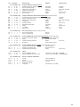
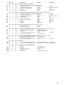
Lfd. Stückzahl Bezeichnung Material Abmessungen
KIT RR RR+ RTF Propeller, Mitnehmer, Spinner Panda
70
71
72 0 0 *0/1 1 Mitnehmer mit Spannkonus Metall Ø2,3 / M6 / 6kt SW13
73 0 0 *0/2 2 Klappluftschraubenblatt Kunststoff 6 x 3"
74 2 2 2 2 Blech-Linsenschraube Metall Ø 2,2 x 6,5mm
75 0 0 *0/2 2 Senkschraube Metall M2 x 12mm
KIT RR RR+ RTF Propeller, Mitnehmer, Spinner-Set Panda Sport
80
81
82 1 1 *1/0 0 Mitnehmer mit Spannkonus Metall Ø3,2 / M6 / 6kt SW13
83 2 2 *1/0 0 Stoppmutter Metall M3
84 2 2 *1/0 0 Zylinderschraube Metall M3 x 18mm
85
86 1 1 1 1 Mutter Metall M6 DIN 934
87 1 1 1 1 U-Scheibe Metall Øi 6,4
88 1 1 1 1 Zahnscheibe Federstahl Øi 6,4
KIT RR RR+ RTF Servos für Rumpf
90 0 1 1 1 Servo für Seitenruder Nano-S
91 0 1 1 1 Servo für Höhenruder Nano-S
KIT RR RR+ RTF Antrieb PERMAX BL-O 2812-1100 für Panda Sport
96 0 1 *1/0 0 Regler MULTIcont BL-20 SD
98 0 0 *1/0 1 Empfänger RX-3 cont M-Link ID 8
KIT RR RR+ RTF Antrieb PERMAX 400 6V für Panda
101 0 0 1 1 Empfänger / Regler Einheit RX-5 M-Link ID 10
KIT RR RR+ RTF Akkus
Panda
Panda Sport
KIT RR RR+ RTF Sender, Ladegerät und Zubehör
105 0 0 0 1 Sender Smart SX Mode 1/3
106 0 0 0 1 Sender Smart SX Mode 2/4
108 0 0 0 1 Anleitung Smart SX

12
GB
Safety Information for MULTIPLEX model aircraft
This model is NOT A TOY in the usual sense of the term.
This model must not be operated by any child under fourteen years of age. If a person below this age operates the model
under the supervision of a competent adult who is acting as the child’s guardian within the legal sense of the term, this
individual is responsible for the implementation of the information in the OPERATING INSTRUCTIONS.
THE MODEL AND ASSOCIATED ACCESSORIES MUST BE KEPT OUT OF THE REACH OF CHILDREN UNDER THREE
YEARS OF AGE! MODELS CONTAIN SMALL DETACHABLE PARTS WHICH MAY BE SWALLOWED BY CHILDREN
UNDER THREE YEARS. CHOKING HAZARD!
All the warnings in the OPERATING INSTRUCTIONS must be observed whenever the model is operated. Multiplex
Modellsport GmbH & Co. KG accepts no liability for loss or damage or any kind which occurs as a result of incorrect
operation or misuse of this product, including the accessories required for its operation. This includes direct, indirect,
deliberate and accidental loss and damage, and all forms of consequent damage.
Every safety note in these instructions must always be observed, as all the information contributes to the safe opera-
tion of your model. Use your model thoughtfully and cautiously, and it will give you and your spectators many hours of
property damage and severe personal injury. You alone bear the responsibility for the implementation of the operating
instructions and the safety notes.
Approved usage
The model is approved exclusively for use within the modelling hobby. It is prohibited to use the model for any other
purpose than that stated. The operator of the model, and not the manufacturer, is responsible for damage or injury of
any kind resulting from non-approved use.
The model may only be operated in conjunction with those accessories which we expressly recommend. The recom-
mended components have undergone thorough testing, are an accurate match to the model, and ensure that it functions
safely. If you use other components, or modify the model, you operate it at your own risk, and any claim under guarantee
is invalidated.
To minimise the risk when operating the model, please observe the following points:
zThe model is guided using a radio control system. No radio control system is immune to radio interference, and
such interference may result in loss of control of the model for a period of time. To avoid collisions, you must
therefore ensure at all times that there is a wide margin of safety in all directions when operating your model. At
the slightest sign of radio interference you must cease operating your model!
zNever operate your model until you have successfully completed a thorough check of the working systems, and
carried out a range-check as stipulated in the instructions supplied with your transmitter.
z
z
have an adverse effect on visual acuity and reaction time.
z
Even when the wind is light, bear in mind that turbulence can form at and around objects which may have an
effect on the model.
z
cables, open roads and railway lines.
z
piloting skill, but all it does is place others at unnecessary risk. It is in all our interests that you let other pilots
mind that even the best RC system in the world is subject to outside interference. No matter how many years of

13
Residual risks
Even if the model is operated in the correct manner, and you observe all safety aspects, there is always a certain residual
risk.
For this reason it is mandatory to take out third-party liability insurance
is usually available or included in the annual fee. Make sure that your insurance cover is adequate (i.e. that it covers
The following hazards may occur owing to the model’s construction and type:
zInjury caused by the propeller: you must keep well clear of the area around the propeller from the moment that
the battery is connected. Please bear in mind that objects in front of the propeller may be sucked into it, and
objects behind the propeller may be blown away by it. The model may start moving when the propeller starts
to turn. You must therefore position the model in such a way that it cannot move towards other persons if the
motor should unexpectedly start running. When you are carrying out adjustment work involving the running
motor, you must ensure that the model is always held securely by an assistant.
z
safe environment: an and suitable insurance are basic essentials.
zCrash caused by technical failure or unnoticed damage in transit or in the workshop. A thorough check of the
z
-
quent damage.
zFire hazard caused by electronic failure or malfunction. Store batteries safely, and always observe safety
notes which apply to the airborne electronic components, the battery and the battery charger. Protect all elec-
tronic equipment from damp. Ensure that the speed controller and battery are adequately cooled.
The instructions which accompany our products must not be reproduced and / or published, in full or in part, in
print or any electronic medium, without the express written approval of Multiplex Modellsport GmbH & Co. KG.
GB

14
KIT Panda Sport # 21 4268
Examine your kit carefully!
MULTIPLEX model kits are subject to constant quality checks throughout the production process, and we sincerely hope
have inspected it. Please send the component to our Service Department, with adequate postage pre-paid, being sure to
include the completed complaints form. We are constantly working on improvements to our models, and for this reason
we must reserve the right to change the kit contents in terms of shape or dimensions of parts, technology, materials and
agree in every respect with the instructions and the illustrations.
Caution!
Radio-controlled models, and especially model aircraft, are by no means playthings in the usual sense of the
term. Building and operating them safely requires a certain level of technical competence and manual skill,
Since we, as manufacturers, have no control over the construction, maintenance and operation of our products, we are
obliged to take this opportunity to point out these hazards and to emphasise your personal responsibility.
Warning:
Like every aeroplane, this model has static limits. Steep dives and senseless manoeuvres inappropriate to the type
may result in the loss of the aircraft. Please note: we will not replace the model in such cases. It is your responsibility to
approach the airframe’s limits gradually. It is designed for the power system recommended in these instructions, but is
Airborne radio control system components / other accessories
Recommended equipment:
MULTIPLEX receiver, min. RX-5 light M-LINK Order No. 5 5808
or
RX-5 M-LINK receiver, telemetry-capable Order No. 5 5817
With this receiver you can also use the telemetry modules, and equip your model
Servos
6 5120
or
6 5119
“Panda Sport” power set, Li-BATT powered Order No. 33 3662
containing PERMAX BL-O 2812-1100 brushless motor,
Power set:
“Panda Sport” power set Order No. 33 2662
containing PERMAX BL-O 2812-1100 brushless motor, MULTIcont BL-20 SD speed controller,
Recommended battery:
15 7321
Adhesives:
Zacki ELAPOR ® 20 g Order No. 59 2727
Zacki ELAPOR ® Super liquid 10 g Order No. 59 2728
Battery charger:
MULTIcharger LN-3008 EQU and AC / DC 230V / 12V 5.0A PSU combo Order No. 9 2545
Tools:
Balsa knife, various slot-head and cross-point screwdrivers, 10 mm A/F open-ended or socket spanner.
Model Service Box Order No. 8 5500
GB

15
Important note
This model is not made of Styrofoam™, and it is not possible to glue the material using white glue, polyurethane or
for ELAPOR® particle foam. If you se Zacki ELAPOR® there is usually no need for cyano ‘kicker’ or activator. However,
if you wish to use a different adhesive which requires the use of activator, please note that these materials are injurious
to health, and should always be applied in the open air. Take care when handling all cyano-acrylate adhesives, as they
goggles to protect your eyes. Keep the adhesive out of the reach of children! For certain joints it is also possible to use
Working with Zacki ELAPOR®
foam parts.
Please observe the following points in order to obtain perfect joints:
allow it to air-dry for about thirty seconds.
not required. All you have to do is moisten the mating surface very lightly with a damp cloth or sponge.
it is easy to straighten again. In this respect ELAPOR® behaves in a similar way to metal: bend the component
back slightly beyond the correct position, and the material will then spring back to its proper shape when released,
and maintain it. There are limits, however - don’t overdo it!
Bent parts - really do exist.
very lightly as if you were cleaning the model. Paint must always be applied thinly and evenly, otherwise the component
will warp. Then you really will have bent parts, and they will also be heavy and perhaps even unusable. We have found
Wingspan 1160 mm 1160 mm
Overall length 800 mm 800 mm
RC functions:
Elevator, rudder, throttle
The Centre of Gravity should be located 55 mm aft of the root leading edge of the wing. The position is indicated by
small pimples on the underside of both wing roots.
Note: please separate the illustration pages from the centre of the building instructions.
1. Before starting construction
Check the contents of your kit before starting work on the
Figs. 1 + 2 and the Parts List helpful
at this stage.
2. Preparing the elevator and rudder servos
MULTImate or your RC system transmitter (don’t forget to
Locate the servo output levers with 1 mm Ø output holes,
case. At a later stage the pushrods will be connected to
All the other arms can be cut off using side-cutters, as can
the excess length of the remaining arm.
Fig. 03
Note: the splines of some servo output levers are designed
output shaft at exactly 90°, turn it through 180° and try again.
3. Installing the servos in the servo mounts
Slip the servo lead through the servo mount 43, then push
the servo down into the frame so that the two retaining clips
snap over the servo mounting lugs.
Fig. 03

16
4. Gluing the servos in the fuselage shells
Apply glue to the outside faces of the servo mounts 43,
as shown.
Note that the output shaft of the servo in the right-hand
fuselage shell 4
shell 3 should be at the front.
Deploy the servo leads in the appropriate channels, running
to the fuselage sides, so that they cannot get in the way
when the two fuselage shells are joined. Figs. 04 + 05
5. Preparing the control snakes
Cut down the snake sleeves to the following length:
Elevator snake 63 2 Ø / 1 Ø x 470 mm
Rudder snake 64 2 Ø / 1 Ø x 500 mm
Note: the best way to shorten the snake sleeves is to
hold a balsa knife in the correct position, and then roll the
be snapped at the scored point. This procedure does not
distort or squash the sleeve, ensuring that the steel inner
pushrod will slide smoothly.
6. Preparing the steel pushrods
Cut down the steel inner pushrods to the following length:
Elevator pushrod 61 1 Ø x 535 mm
Rudder pushrod 62 1 Ø x 565 mm
Now slip the pushrod 61 in the sleeve 63 - both parts are
the longer versions. Slip the rod 62 in the sleeve 64 - both
parts are the shorter versions.
7. Deploying the control snakes in the fuselage
Start with the right-hand fuselage shell 4: connect the pre-
62 to the right-
hand servo output arm. Now gently bend the pushrod and
snake sleeve to the point where they can be slipped through
the slot in the tail end of the fuselage. Position the sleeve so
that it ends at the foam block immediately aft of the servo.
Tack the sleeve in place initially with a few drops of glue,
so that it cannot fall out. It is glued in place permanently at
a later stage, when the square aluminium tube is installed.
Fig. 06
Continue with the left-hand fuselage shell 3: connect the
shorter pushrod 61 to the servo output arm. In this case
position the snake sleeve so that it ends at the point where
the channel opens out into the tailplane crank chamber at
the tail end of the fuselage.
Fig. 07
8. Installing the fuselage stiffener tube
Locate the square aluminium fuselage stiffener tube 65
fuselage shell 4, pushing it full-depth into the channel. Take
care to keep it perfectly straight: sight along the bottom
edge of the fuselage from the tail end, and ensure that the
fuselage is dead straight.
Fig. 06
9. Joining the two fuselage shells
Hold the two fuselage shells 3 + 4 together “dry” (without
properly.
Apply adhesive to the contact surfaces of the fuselage
shells and the aluminium stiffener tube 65, leaving a gap
about 5 mm wide at the outside edges, so that the glue is
not forced out of the joints. Place the parts together and
set the fuselage exactly straight. Apply a few strips of tape
across the joints while the glue is hardening. Sight along
the bottom edge of the fuselage joint seam from the tail end
to check that the fuselage really is straight.
Fig. 08
Note: you will surely have noticed that the servo leads are
now permanently trapped. Normally you will never have to
replace a servo, but if this should prove necessary, you can
cut away the foam block between the servos, then glue it
back in place after installing the replacement.
10. Installing the motor in the fuselage nose fairing
The Panda Sport brushless power set # 33 3662 includes a
suitable rechargeable battery, and forms the perfect power
system for the model.
The components supplied in this power set have been
extensively tested, and are accurately matched to each
other. If you prefer to use a different battery, speed controller,
motor or RC system components, that is up to you, but we
would then be unable to provide support if a problem were
to occur.
Fix the PERMAX BL-O 2812-1100 electric motor to the
fuselage nose fairing / motor bulkhead 42.1 using two of
the M3 x 6 mm machine screws and washers included in
motor wires on the underside of the fuselage.
Fig. 09
11. Gluing the nose fairing to the fuselage
Hold the nose fairing 42.1 - with motor attached - against
exactly central. The best method of centring it accurately
is to look at the fuselage from the underside, and line up
the fairing with the cut-out in the fuselage located behind it.
the nose fairing to the foam fuselage, applying adhesive to
the whole of the contact area. Allow plenty of time for this
propeller blades and the prop driver.
Fig. 10
12. Assembling the folding propeller blades
85 to the
propeller hub 80 using the M3 x 18 mm cheesehead screws
84 and M3 self-locking nuts 83. Tighten the screws just to
blades, but they still fold back smoothly.
Fig. 11
13. Installing the fuselage hatch frame in the fuselage
Locate the hatch frame 40.1
and squeeze the narrow rails together slightly so that it can
Press the rails fully against the foam sides and into the
41.1

17
remove the hatch and frame, apply glue to the outside
contact surfaces, and repeat the procedure. Don’t forget
to engage the fuselage hatch again while the glue is still
soft, so that everything is held in the correct position while
the adhesive sets hard.
Fig. 12
Note: production tolerances may make it necessary to cut
away the foam very slightly where the rear of the hatch
14. Installing the receiving system components
The positioning of the RC components has a minor but
useful effect on the model’s Centre of Gravity. Final
Connect the MULTIcont BL-20 SD speed controller to the
top of the fuselage using the hook-and-loop tape 20 +
21. Install the M-LINK
fuselage, in the empty space aft of the servos. Route the
aerial out of the cooling air exit opening, and tape it to the
fuselage. The Li-BATT FX 3/1-950
to the fuselage side at the front, below the speed controller,
again using hook-and-loop tape. Group the cables together
adhesive or adhesive tape.
Fig. 13
Note: since the “grip” of the hook-and-loop tape is greater
than the adhesion between the sticky coating and the foam
surface, we recommend gluing the tape in place using hot-
15. Initial test-run of the motor
Note:
until you have switched on your transmitter, and are certain
that the control which operates the motor is at the “OFF”
position.
of rotation of the motor using your radio control transmitter
swap over any two of the three wires attached to the motor.
16. Mounting the propeller and spinner on the model
Press the prop driver and taper collet 82 into the propeller
hub 80. Fit the washer 87, shakeproof washer 88 and M6
nut 86 loosely on the threaded shaft.
Fig. 11
Now slide the whole assembly onto the motor shaft, and
set a clearance gap of about 1 mm between the back of the
propeller hub 80 and the front face of the fuselage.
Tighten the nut, and check once more that the clearance
between prop driver and fuselage has not changed since
you wielded the spanner! Attach the spinner 81 using the
two 2.2 x 6.5 mm self-tapping screws 74.
Fig. 14
17. Preparing the tailplane crank
Fit the spigot of the swivel pushrod connector 25 through
the hole in the tailplane crank 50, check that it is the right
26
and nut 27
the pushrod connector swivels smoothly and freely. When
Insert the socket-head grubscrew 24 in the open end of the
swivel connector barrel using the allen key 28.
Fig. 15
9 until it moves freely. Glue the tailplane pivot
housing 46
Fig. 16
Note: take care to prevent adhesive being forced into the
Ø drill bit through the holes to remove glue residues.
19. Rudder horn
Snap the articulated barrel 23 into the “twin horn” 22, then
24 in the articulated barrel
using the allen key. Angle the horn forward and glue it in the
appropriate recess in the bottom of the rudder.
Fig. 17
20. Completing the tailplane
Glue the “tailplane joiner and shaft” 48 in the left-hand
tailplane panel 7.
Fig. 18
Glue the “tailplane joiner and retainer” 49 in the right-hand
tailplane panel 8, taking care to apply the glue sparingly,
so that it cannot be forced inside the socket.
Fig. 19
Note: before joining the tailplane panels it is important to
allow the glued joints to harden completely, otherwise you
may never be able to separate the tailplane!
To dismantle the system, locate the point marked “X” on the
tailplane 8, and press it in to release the retainer.
Fig. 19
Completing the wing panels
21. Preparing the tubular spars
Apply a little glue to the spar joiner 44, and push it onto the
aluminium tubular spar 60
the tip of the mushroom-head self-tapping screw 31 in the
hole in the side of the spar joiner, then drive the screw in as
far as it will go using a suitable cross-point screwdriver (with
task easier by drilling a 1.5 mm Ø pilot-hole in the aluminium
beforehand. The spar joiner is symmetrical, so it makes no
Fig. 20
22. Gluing the tubular spars in the wing panels
Locate the right-hand wing panel 6, and apply Zacki
ELAPOR to the three contact surfaces in the spar recess.
check immediately that it is aligned correctly.
Figs. 21 + 22
Fit the wing retainer 45 loosely on the tubular spar 60 before
gluing the spar in the left-hand wing panel 5 in the same

18
manner. Ensure that the wing retainer 45 remains free to
this stage.
The wing retainer 45 is eventually glued to the spar once you
Figs. 23 + 24
The wing panels can now be plugged into the fuselage: lay
the model on its back and push the wings together fully,
so that there is no lost motion at the joint, and engage the
wing retainer 45 on the toothed section in such a way that
the two injection-moulded plastic parts. In this position
tack the retainer to the tubular spar by applying a small
amount of Zacki ELAPOR Super liquid just in the gap at
the point shown in the picture. Allow the glue to set hard,
then carefully dismantle the model and apply more glue to
the wing retainer if necessary. The wings are separated by
pulling the lug forward towards the wing leading edge with
Fig. 25
Note: if the wing retainer system should become loose
24. Installing the tailplane crank in the fuselage
Swivel the elevator servo output lever forward, in order to
create a little “working room” for the steel pushrod at the
tail end. Turn the tailplane crank 50 through 90° and slip
the steel pushrod through the hole in the swivel pushrod
connector 25. At the front end, move the servo output arm
back to the neutral position before tightening the grubscrew
in the pushrod connector with the allen key, working through
the hole in the side of the fuselage.
Fig. 26
9
in the pivot housing 46. When you are sure that everything
Zacki ELAPOR to
the joint surfaces, and repeat the procedure, taking care to
Fig. 27
Note:
panels into the fuselage. You can then sight along the
exactly vertical.
Fig. 34
26. Installing the tailplane crank in the pivot housing
Fit the tailplane crank 50 in the pivot housing 46, then seal
the housing with the cover 47 and the M2 x 10 mm screws
29. Check that the system moves smoothly and freely, and
make any adjustments required.
Fig. 28
pushing them together until the latch engages.
Fig. 29
Note: it is essential that the tailplane should pivot freely.
compress the foam slightly at the root face of the tailplane
panels. The easiest method of doing this is to place the
root face of the tailplane panel on the edge of a table, and
slide it to and fro using moderate pressure. Alternatively the
foam can be trimmed back very slightly using a balsa knife.
27. Checking the model
Assemble the model completely, and ensure that the
airframe is “straight and square”. All the receiving system
components must be installed and connected correctly.
Check the control surface travels and the direction of
rotation of the servos. Ensure that all the mechanical control
systems are free-moving. Check that the wires attached to
the motor cannot make contact with the rotating section of
motor rotates in the correct direction. Figs. 30 + 34
28. Setting the control surface travels (recommended
values only!)
model is to respond in a harmonious manner to control
commands. The travels are measured at the widest point
of each control surface.
Elevator: 10 / 10 mm +/-
Rudder: 15 / 15 mm +/-
The tailplane is at the correct neutral point when the socket-
head grubscrew is visible through the hole in the side of the
fuselage. Be sure to set the elevator servo exactly to centre
before you tighten the grubscrew!
Fig. 33
29. Applying the decals
A decal sheet 2.2 is included in the kit. The individual name
placards and other motifs are pre-cut, and can be applied to
the model in accordance with our suggested layout (kit box
Caution: the circular stickers are used later to seal the
ballast chambers once you have set the correct Centre of
Gravity - so don’t throw them away!
recommend our range of “ELAPOR® Color” spray cans #
30. Colouring the canopy
using a waterproof felt-tip pen, or alternatively masked off
Color” spray paints in the FAQ section on our website.
31. Setting the Centre of Gravity
The correct Centre of Gravity can be set by adjusting the

19
adding ballast if required. The CG should be located 55 mm
back from the wing leading edge, measured where the wings
pimples on the underside of the wings. Support the fully
the fuselage should now remain horizontal, with the nose
inclined slightly down.
If necessary, add trim ballast 30
then cover the recesses with the circular stickers from the
decal sheet.
Fig. 32
For the first flight please wait for a day with as little
evening hours. If you are a beginner to radio-controlled
model aircraft, we strongly recommend that you ask an
experienced modeller to help you, as it is extremely likely
that things will go wrong if you try to “go it alone”. If in
model shop will also be able to supply the address of clubs
in your area.
keep to the procedure recommended by the radio control
system manufacturer.
full charge in accordance with the battery manufacturer’s
using a 2.4 GHz radio control system, check that “your”
channel is not already in use.
far better to pack up the whole system (including battery,
Service department for checking.
The aircraft is designed to be hand-launched (always into
that you ask an experienced modeller to help you for the
adjust the control surfaces using the trims on the transmitter,
altitude, check how it responds when the motor is switched
off, so that you are familiar with its behaviour on the glide.
Carry out repeated simulated landing approaches at a safe
height, as this will prepare you for the real landing when the
battery is discharged.
and in particular during the landing approach. It is always
better to land safely some distance away than to risk a crash
by forcing the model back to your feet.
34. Slope soaring
Staying aloft for hours on end in slope lift, without needing
over the valley, search for a thermal, locate the lift, circle
up, “milking” it to the limits of vision (take care - the model is
of aerobatic manoeuvres, and then repeat the whole show
- that must surely be one of the greatest of all pleasures
in modelling. At the same time the electric power system
provides a means of bringing the model “back home” at any
time if the lift should fail, thereby eliminating the old fear of
“landing out” in the valley.
35. Trainer mode operations
the model ideal as a practice machine. With the wireless
Trainer Stick # 4 5183, two MULTIPLEX transmitters and
an experienced tutor, the beginner can swiftly learn the art
pupils are capable of controlling the model by themselves
after just a short period of tuition.
Any 2.4 GHz M-LINK transmitter can be used as Pupil
transmitter, while the Teacher transmitter can be any
MULTIPLEX transmitter featuring a DIN multi-function
socket and Teacher functionality - regardless of the
frequency band, i.e. 2.4 GHz M-LINK* or xx MHz. There
is no connecting lead to hinder the pilots’ movements, and
if necessary.
36. Safety
aircraft. Third party insurance is mandatory. If you join a
model club, suitable cover will usually be available through
the organisation. It is your personal responsibility to ensure
that your insurance is adequate (i.e. that its cover includes
models and your radio control system in perfect order at all
times. Check and observe the correct charging procedure
for the batteries you are using. Make use of all sensible
safety systems and precautions which are advised for
your system. An excellent source of practical accessories
is the MULTIPLEX main catalogue or our website www.
multiplex.de
MULTIPLEX products are designed and manufactured
exclusively by active modellers for practising modellers.
prove himself in such childish ways. Let other pilots know
that this is what you think too, as it is in all our interests.
or others. Bear in mind that even the best RC system in
the world is subject to outside interference. No matter how
belt, you have no idea what will happen in the next minute.
in turn that each control surface is operating correctly!
We - the MULTIPLEX team - hope you have many hours of
MULTIPLEX Modellsport GmbH &Co. KG

20
Available versions
# 21 4268 KIT Panda Sport Kit
# 26 4268 RR Panda Sport Ready-built model, servos, controller, BL-O 2812-1100 motor
#*26 4272 *RR+ Panda Sport Ready-built model, servos, controller, BL-O 2812-1100 motor, receiver, battery
# 26 4269 RR+ Panda Ready-built model, servos, controller / receiver, 400 6V motor, battery
# 1 3268 RTF Panda Ready-built, servos, controller / receiver, 400 6V motor, transmitter, battery, charger
# 1 3269 RTF Panda Ready-built, servos, controller / receiver, 400 6V motor, transmitter, battery, charger
To help you when assembling the model it is a good idea to use a coloured highlighter to mark your own version in the Parts List below.
Parts List - Panda / *Panda Sport
Part No. Quantity Description Material Dimensions
KIT RR RR+ RTF
1 1 1 1 1 KIT building instructions
1.1 0 1 0 0 RR supplementary instructions
1.2 0 0 1 0 RR+ supplementary instructions
1.3 0 0 0 1 RTF supplementary instructions
1.4 0 1 *1/0 0 “Panda SPORT” power set instructions
1.5 0 1 *1/0 0 BL speed controller instructions
1.7 1 1 1 1 Model complaint processing form
2.1
2.2
3 1 1 1 1 L.H. fuselage shell Moulded Elapor foam
4 1 1 1 1 R.H fuselage shell Moulded Elapor foam
5 1 1 1 1 L.H. wing panel Moulded Elapor foam
6 1 1 1 1 R.H. wing panel Moulded Elapor foam
7 1 1 1 1 L.H. tailplane panel Moulded Elapor foam
8 1 1 1 1 R.H. tailplane panel Moulded Elapor foam
9 1 1 1 1 Fin Moulded Elapor foam
KIT RR RR+ RTF Small parts set
20 3 3 3 3 Hook-and-loop tape, “hook” Plastic 25 x 60 mm
21 3 3 3 3 Hook-and-loop tape, “loop” Plastic 25 x 60 mm
22 1 1 1 1 “Twin” control surface horn Plastic Ready made
23 1 1 1 1 Articulated swivel connector barrel Metal Ready made, 6 mm Ø
24 2 2 2 2 Socket-head grubscrew Metal M3 x 3 mm
25 1 1 1 1 Swivel pushrod connector Metal Ready made, 6 mm Ø
26 1 1 1 1 Washer Metal M2
27 1 1 1 1 Nut Metal M2
28 1 1 1 1 Allen key Metal 1.5 mm A/F
29
30 50 50 50 50 Trim ballast Metal balls 4 mm Ø, approx.15 g
31
KIT RR RR+ RTF Plastic parts set
40
40.1
41
41.1
42
42.1
43 2 2 2 2 “Nano” servo mount, upright Plastic Ready made
44 1 1 1 1 Spar joiner Plastic Ready made
45 1 1 1 1 Wing retainer Plastic Ready made
46 1 1 1 1 Tailplane pivot housing Plastic Ready made
47 1 1 1 1 Tailplane pivot housing cover Plastic Ready made
48 1 1 1 1 Tailplane joiner and shaft Plastic Ready made
49 1 1 1 1 Tailplane joiner and retainer Plastic Ready made
50 1 1 1 1 Tailplane crank Plastic Ready made
KIT RR RR+ RTF Wire and spar set
60 2 2 2 2 Wing spar Square aluminium 8 x 6 x 300 mm
61 1 1 1 1 Wire elevator pushrod, pre-formed Metal 0.8 Ø x 535 mm
62 1 1 1 1 Wire rudder pushrod, pre-formed Metal 0.8 Ø x 565 mm
63
64 1 1 1 1 Rudder snake sleeve Plastic 2/1 Ø x 500 mm
65 1 1 1 1 Fuselage stiffener tube Square aluminium 8 x 6 x 380 mm
GB
La page est en cours de chargement...
La page est en cours de chargement...
La page est en cours de chargement...
La page est en cours de chargement...
La page est en cours de chargement...
La page est en cours de chargement...
La page est en cours de chargement...
La page est en cours de chargement...
La page est en cours de chargement...
La page est en cours de chargement...
La page est en cours de chargement...
La page est en cours de chargement...
La page est en cours de chargement...
La page est en cours de chargement...
La page est en cours de chargement...
La page est en cours de chargement...
La page est en cours de chargement...
La page est en cours de chargement...
La page est en cours de chargement...
La page est en cours de chargement...
La page est en cours de chargement...
La page est en cours de chargement...
La page est en cours de chargement...
La page est en cours de chargement...
La page est en cours de chargement...
La page est en cours de chargement...
La page est en cours de chargement...
La page est en cours de chargement...
La page est en cours de chargement...
La page est en cours de chargement...
La page est en cours de chargement...
La page est en cours de chargement...
La page est en cours de chargement...
La page est en cours de chargement...
La page est en cours de chargement...
La page est en cours de chargement...
La page est en cours de chargement...
La page est en cours de chargement...
La page est en cours de chargement...
La page est en cours de chargement...
La page est en cours de chargement...
La page est en cours de chargement...
-
 1
1
-
 2
2
-
 3
3
-
 4
4
-
 5
5
-
 6
6
-
 7
7
-
 8
8
-
 9
9
-
 10
10
-
 11
11
-
 12
12
-
 13
13
-
 14
14
-
 15
15
-
 16
16
-
 17
17
-
 18
18
-
 19
19
-
 20
20
-
 21
21
-
 22
22
-
 23
23
-
 24
24
-
 25
25
-
 26
26
-
 27
27
-
 28
28
-
 29
29
-
 30
30
-
 31
31
-
 32
32
-
 33
33
-
 34
34
-
 35
35
-
 36
36
-
 37
37
-
 38
38
-
 39
39
-
 40
40
-
 41
41
-
 42
42
-
 43
43
-
 44
44
-
 45
45
-
 46
46
-
 47
47
-
 48
48
-
 49
49
-
 50
50
-
 51
51
-
 52
52
-
 53
53
-
 54
54
-
 55
55
-
 56
56
-
 57
57
-
 58
58
-
 59
59
-
 60
60
-
 61
61
-
 62
62


MULTIPLEX Panda Sport Building Instructions
- Catégorie
- Jouets télécommandés
- Taper
- Building Instructions
dans d''autres langues
- italiano: MULTIPLEX Panda Sport
- English: MULTIPLEX Panda Sport
- español: MULTIPLEX Panda Sport
- Deutsch: MULTIPLEX Panda Sport
Documents connexes
-
MULTIPLEX Panda Le manuel du propriétaire
-
-
-
-
-
MULTIPLEX 2 Heron Le manuel du propriétaire
-
-
MULTIPLEX RR+ EasyStar II Le manuel du propriétaire
-
-
Autres documents
-
 J-Power Group Eurofighter Assembly And Operating Instructions Manual
-
 Fischer Panda Panda 5000i.Neo PMS Le manuel du propriétaire
-
 Fischer Panda Panda 15000i-400V PMS Le manuel du propriétaire
-
 Fischer Panda Panda 45i PMS Le manuel du propriétaire
-
 Fischer Panda Panda 10000i PMS Le manuel du propriétaire


