La page est en cours de chargement...

INDOOR/OUTDOOR PRODUCTS
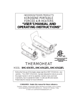
KEROSENE PORTABLE
FORCED AIR HEATER
“USER’S MANUAL AND
OPERATING INSTRUCTIONS”
carefully. This USER’S MANUAL has been designed to instruct you as to
the proper manner in which to assemble, maintain, store, and most
Please keep this manual for future reference.
COMPLIES WITH UL733 AND
CAN/CSA/B140.0-03 AND
CSA B140.8-1967
CONSUMER : Retain this manual for future reference.
Questions, problems, missing parts? Before returning to your retailer, call our customer
service department at 877-447-4768 8:30 a.m. - 4:30 pm CST, Monday - Friday.
or email us at customerservice@ghpgroupinc.com
IMSFDG - KDS
MODEL: SF70DGD MODEL: SF70H

1
DANGER: IMPROPER USE OF THIS HEATER CAN RESULT IN SERIOUS INJURY OR DEATH
FROM BURNS, FIRE, EXPLOSION, ELECTRICAL SHOCK AND/OR CARBON
MONOXIDE POISONING.
WARNINGS:
1. RISK OF INDOOR AIR POLLUTION!
• Use this heater only in well ventilated areas. Provide at least a three-square foot (2,800 sq. cm.)
opening of fresh outside air for each 100,000 BTU/hr. of heater rating.
• People with breathing problems should consult a physician before using the heater.
• Carbon monoxide poisoning:
headaches, dizziness
and/or nausea. If you have these signs, the heater may not be working properly.
Get fresh air at once! Have the heater serviced. Some people are more affected by carbon monoxide than others.
These include pregnant women, persons with heart or lung diseas
those at high altitudes.
• Never use this heater in living or sleeping areas.
2. RISK OF BURNS / FIRE / EXPLOSION!
• NEVER use any fuel other than 1-K kerosene, #1/#2 disel/fuel oil, JET A or JP-8 fuels in this heater.
• NEVER use use fuel such as gasoline, benzene, paint thinners or other oil compounds in this heater.
(RISK OF FIRE OR EXPLOSION)
• NEVER
• NEVER ill hot.
CAUTION:
Hot while in operation. Do not touch. Keep children,
clothing and combustibles away from heater.
Minimum Clearances: Outlet: 8 feet (250cm) / Sides, top and rear: 4 feet (125cm)
• NEVER block air inlet (rear) or air outlet (front) of heater.
• NEVER use duct work in front or behind of heater.
• NEVER move or handle heater while it is hot, operating, or plugged in.
• NEVER transport heater with fuel in it’s tank.
• When used with an optional thermostat or if equipped with a thermostat, heater may start at any time.
• A
LWAYS locate heater on a stable and level surface.
• ALWAYS keep children and animals away from heater.
• Bulk fuel storage should be a minimum of 25 ft. from heaters, torches, portable generators or other sources of ignition.
All fuel storage should be in accordance with federal, state or local authorities having jurisdiction.
3. RISK OF ELECTRIC SHOCK!
•
on the model plate of the heater.
• Use only a three-prong, grounded outlet and extension cord.
• ALWAYS install the heater so that it is not directly exposed to water spray, rain, dripping water or wind.
• ALWAYS unplug the heater when not in use.
MASSACHUSETTS RESIDENTS: Massachusetts state law prohibits the use of this heater in any
building which is used in whole or in part for human habitation. Use of this heating device in
CANADIAN RESIDENTS: Use of this heater shall be in accordance with authorities having
jurisdiction and CSA Standard B139.
NEW YORK CITY RESIDENTS: For use only at construction sites in accordance with applicable NYC
NEVER LEAVE THE HEATER
UNATTENDED WHILE BURNING!
WARNING: This product and the fuel used to operate this product (kerosene or other
approved fuels), and the products of combustion of such fuel, can expose you to chemicals including
benzene, which is known to the State of California to cause cancer and reproductive harm.
For more information go to www.p65Warnings.ca.gov

2
NEVER LEAVE THE HEATER
UNATTENDED WHILE BURNING!
ITEM
EDIUG YTEFAS - SNOITUACERP
1. INTRODUCTION
2. FEATURES
3. UNPACKING AND ASSEMBLY
4. FUEL SELECTION
5. OVERVIEW OF HEATER DESIGN
6. FUELING YOUR HEATER
7. OPERATION
8. LONG TERM STORAGE OF YOUR HEATER
9. MAINTENANCE
10. TROUBLE SHOOTING GUIDE
11. WIRING DIAGRAM
12. SPECIFICATIONS
13. EXPLODED PARTS DRAWING
14. PARTS LIST
1. INTRODUCTION
2. FEATURES
Please read this USER’S MANUAL carefully. It will show you how to assemble, maintain, and operate the
heater safely and efficiently to obtain full benefits from its many built-in features.
CONTENTS OF USER’S MANUAL
PAGE #
1
2
2
3
4
5
5
6
7
7
11
12
12
13
14
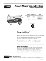
Figure 1. SF70DGD/SF70H Model
Hot Air Outlet
Front Guard
Shell Ring
Shell Supporter
Fuel Tank
Shell
Handle
Back Cover
Fuel Cap
Fuel Gauge
Power Cord
Heat Shield
Operating Switch
Lamp
Power Cord

NEVER LEAVE THE HEATER
UNATTENDED WHILE BURNING!
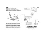
Figure 2. Packing Materials
Figure 3. Assembling Handle, Heat Shield
1. UNPACKING
REMOVE THE HEATER AND ALL PACKING
MATERIALS FROM THE BOX.( Fig. 2 )
NOTE : Save the shipping carton and packing materials
for future storage.
2. ASSEMBLY
Tools Required
• Medium Phillips Screw driver.
3. UNPACKING AND ASSEMBLY
Bolt
Remove Bolts
Remove Bolts
Bolt
Handle
Shell
Shell Ring
Heat Shield
Handle
Heat Shield
1. Remove the pre-assembled Bolts on the shell
and shell ring.
2. Align the holes in the shell with two mounting
holes on the handle as shown in Figure3.
3. Secure handle with Bolts.
4. Align the holes in the shell ring with two
mounting holes on the heat shield as shown in
Figure 3.
5. Secure heat shield with Bolts.
3
CAUTION : DO NOT operate heater without heat shield assembled to the heater.
The heat shield must attached to prevent any damage, discoloration, or deformation to the floor.
NOTE : Heater should be inspected before each use, and at least annually by a qualified service person.

4
NEVER LEAVE THE HEATER
UNATTENDED WHILE BURNING!
4. FUEL SELECTION
1. All models can use 7 different fuels: K1 Kerosene, #1 Fuel Oil, #1, Diesel, #2 Fuel Oil, #2 Diesel, Jet A, JP-8
2. K1 Kerosene is recommended for optimal combustion and performance, and for less maintenance. K1 is also
the optimal fuel choice in extremely low temperatures of 15°F or less, as its pour-point/"gel-point" varies
3. Jet A and JP-8 are also excellent choices for clean combustion, reduced maintenance, and temperatures below
15°F, but they are rarely found outside of the aviation industry or the military.
4. #1 Fuel Oil, #1 Diesel, #2 Fuel Oil, #2 Diesel are often selected, as they are readily available. However, the
following:
a. #1 Diesel and #1 Fuel Oil will have some degree of increased smoke/soot during ignition, increased smell,
and increased regular cleaning/maintenance.
, burn dirtier than #1 fuels. The
use of #2 fuels will result in a little more smoke/soot during ignition, a greater increase in smell, and will
require more regular cleaning/maintenance than #1 fuels.
c. At temperatures lower than 15°F, most diesel/fuel oil blends will become more viscous (start to gel) as
the diesel falls below its pour point (starts to "gel"), and may pose a challenge igniting the heater and with
continuous operation of the heater. There are troubleshooting steps for this situation, but selecting K1 (or
JP-8/Jet A) is recommended when operating below 15°F. The colder the temperatures the more likely you
could problems you will experience diesel gelling.
temperature drops. At 32°F, the wax in liquid form will crystallize and leave the fuel clouded; this can start
correct which can cause white smoke and performance problems.
NEVER store kerosene in the living space. Kerosene should be stored in a well ventilated place outside the
living area.
NEVER use any fuel other than 1-K kerosene (#1/#2 diesel/fuel oil, JET A or JP-8 fuels are acceptable substitutes)
NEVER use fuel such as gasoline, benzene, alcohol, white gas, camp stove fuel, paint thinners, or other oil
compounds in this heater. These are volatile fuels that can cause an explosion or uncontrolled
NEVER store kerosene in direct sunlight or near a source of heat.
NEVER use kerosene that has been stored from one season to the next. Kerosene deteriorates over time.
KEROSENE SHOULD ONLY BE STORED IN A BLUE CONTAINER THAT IS CLEARLY
MARKED “KEROSENE”. NEVER STORE KEROSENE IN A RED CONTAINER.
Red containers are associated with gasoline.
“OLD KEROSENE” WILL NOT BURN PROPERLY IN THIS HEATER.

5. OVERVIEW OF HEATERS DESIGN
The Fuel System :
This heater is equipped with a high-pressure electronic pump. The pump draws fuel up from the fuel tank to
the nozzle in the burner head. It is sprayed into the combustion chamber in a fine mist where it is mixed
with air for combustion.
The Air System :
A blower motor assembly forces air around the combustion chamber, where it is super-heated and forced
out the front of the chamber. A cooling fan blows air up and around the chamber during operation and also
runs during the cool-down period.
The Ignition System :
The electronic ignitor sends High voltage to a specially designed Spark Plug.
The Spark Plug ignites the fuel and air mixture described above.
The Safety System :
A. Temperature Limit Control : This heater is equipped with a Temperature Limit Control designed to turn
off the heater should the internal temperature rise to an unsafe level. If this
device activates and turns your heater off it may require service.
Once the temperature falls below the reset temperature you will be able to start your heater.
B. Electrical System Protection :
The heater's electrical system is protected by a fuse mounted to the
PCB assembly that protects the system components from damage.
If the heater fails, check the fuse first, and replace if necessary.
C. Flame-Out Sensor :
The heater uses photocell to see the flame in the combustion chamber.
Should the flame extinguish, the sensor will stop electrical current and the
heater will shut off.
D. Shock(earthquake) automatic shut-off Device : This Heater is equipped with Tip Over switch,
In case that earthquake more than 5magnitude happens
or that heater inclined 5~10 degrees.
Heater will be shut-off by Tip Over switch for safety.
(Refer to Page 10“Trouble Shooting Guide”)
5
NEVER LEAVE THE HEATER
UNATTENDED WHILE BURNING!
Internal Shut-Off Temp. Reset Temperature
MODELS
Plus/Minus 10 Degrees Plus/Minus 10 Degrees
SF70DGD/SF70H
176˚F/80˚C 158˚F/70˚C
6. FUELING YOUR HEATER
NEVER FILL THE HEATER FUEL TANK IN THE LIVING SPACE : FILL THE TANK OUTDOORS.
DO NOT OVERFILL YOUR HEATER AND BE SURE HEATER IS LEVELED.
IMPORTANT NOTICE REGARDING FIRST IGNITION OF HEATER :
The first time you light the heater, it should be done outdoors. This allows the oils, etc. used in
manufacturing the heater to burn off outside.
WARNING!! :
NEVER REFILL HEATER FUEL TANK WHEN HEATER IS OPERATING OR STILL HOT.

6
NEVER LEAVE THE HEATER
UNATTENDED WHILE BURNING!
7. OPERATION
A.) VENTILATION
RISK OF INDOOR AIR POLLUTION/USE HEATER ONLY IN WELL VENTILATED AREAS.
Provide a fresh air opening of at least three square feet (2,800 sq. cm) for each 100,000 BTU/Hr.
rating. Provide extra fresh air if more heaters are being used.
Example : A SF70DGD heater requires one of the following:
• a two-car garage door raised six inches (15.24 cm)
• a single-car garage door raised nine inches (22.86 cm)
• two, thirty-inch (76.20 cm) windows raised fifteen inches (38.1 cm)
B.) OPERATION
TO START HEATER
1. Fill the tank with kerosene until needle on fuel gauge points to "F".
2. Be sure fuel cap is secure.
3. Plug power cord into three prong, grounded extension cord into three prong 120V grounded outlet.
The extension cord should be at least six feet long.
Extension cord wire size requirements are as follows:
• 6 to 10 feet (1.8 to 3 meters ), use 18 AWG wire.
• 11 to100 feet (3.4 to 30.4 meters ), use 16 AWG wire.
• 101 to 200 feet (30.8 to 61 meters), use 14 AWG wire.
4. Push the Operating Switch to the "ON" position. The power indicator lamp will light
and the heater will ignite after the fan runs for a while. (approx.14sec.)
NOTE : The electrical components of this heater are protected by a fuse mounted in the PCB board.
If the heater fails to fire, check this fuse first, and replace if necessary. Also check the power
source to be sure that the proper voltage is being provided to the heater.
NOTE : In case of the following occurrences:
- Heater exhibits abnormal sputtering sound in the electronic pump while attempting to ignite.
- After filling up of the fuel tank, heater fails to properly ignite during its initial attempt.
- When user attempts to ignite heater following a previously failed ignition attempt with an
empty fuel tank.
- When the flow of fuel is blocked by air that is residing within the fuel line, in these cases,
one should try multiple ignition attempts on their heater.
The occurring noise is a direct result of the heating process as the heater’s pump pushes air
from the fuel line.
The noise should quickly decrease following the ignition of your heater.
It is also not unusual for slight smoke or flames to briefly be seen from the hot air outlet
after heater has ignited.
TO
STOP HEATER
1. Turn the Operating Switch to "OFF" position. Combustion will stop, and the Cooling Cycle
(approx. 5 minutes) will begin.
2. When cooling Cycle is completed (fan stops running), it is safe to unplug the heater.
• Unplugging the heater before the Cooling Cycle has ended may cause overheating,
damage to the heater, and could void the warranty.
A SF70DGD/SF70H heater requires one of the following:

8. LONG TERM STORAGE OF YOUR HEATER
• Remove Fuel Cap and Fuel Cap Filter.
• Remove Kerosene from the tank by using an approved siphon pump
and wash Fuel Cap Filter with clean kerosene.
• Rinse and swirl the kerosene inside the fuel tank by using a small amount of kerosene.
• Make sure the tank is completely empty.
Never leave kerosene in the tank over a long period time because using old kerosene can damage the heater.
9. MAINTENANCE
• Be sure that the storage area is free of dust and corrosive vapors. Repack the original shipping material.
keep the User's Manual in an easily accessible place.
7
NEVER LEAVE THE HEATER
UNATTENDED WHILE BURNING!
Store heater in a dry, well-ventilated area
Screw
Back Cover
Display PCB
wire
Operating Switch
wire
A) BACK COVER REMOVAL
Figure 4. Back Cover Removal
1) Remove 4 Screws along circumference of the Back Cover.
2) Disconnect Operating Switch Wire and Display PCB
wire from PCB Board.
3) Remove Back Cover.
B) FUEL TANK
Flush every 200 hours of operation or as needed
(See above,8.Long term storage of your heater)
WARNING!! : NEVER SERVICE HEATER WHILE IT IS PLUGGED IN OR
WHILE HOT!
USE ORIGINAL EQUIPMENT REPLACEMENT PARTS.
Use of third party or other alternate components
will void warranty and may cause unsafe operating
conditions.
TO RESTART THE HEATER
1.Wait 10 seconds after cooling cycle has completed.
2. Turn the Operating Switch to "ON" position.
3. Be sure to follow all starting procedure precautions.
CAUTION : Do not disconnect the power source or unplug the power cord until the cooling cycle has
been completed!
CAUTION : DO NOT operate heater without heat shield assembled to the heater.
Temperature of the floor is hot while in operation. Use the heater without heater shield,
will cause deformation or discoloration of the floor.
CAUTION : NEVER use an accessory thermostat with this heater.
Accessory thermostat will bypass the cooling cycle after the heater is shuts off
and damage the heater.

NEVER LEAVE THE HEATER
UNATTENDED WHILE BURNING!
C) FUEL FILTER IN FUEL TANK
Clean twice per heating season or as needed
1) Pull Fuel Line off from Fuel Filter neck.
2) Turn Fuel Filter 90˚ to counter clockwise and pull to remove.
3) Remove Fuel Cap and Fuel Cap Filter.
4) Wash Filters with clean kerosene and replace in tank.
5) Attach Fuel Line to Fuel Filter neck.
D) BURNER FULL ASSEMBLY REMOVAL
E) PHOTOCELL
Clean Photocell annually or as needed.
8
Figure 4. Tank Fuel Filter Removal
Figure 5. Burner Full Assembly Removal
Figure 6. Photocell Removal
1) Remove Back Cover(See Page7)
2) Disconnect Cooling M/T Wire from Control PCB.
3) Remove Fuel Line from Fuel Filter.
4) Remove Power Cord from U-shaped Hole in the shell.
5) Remove 3nuts with 8mm socket wrench and remove
Burner Full Assembly from Shell Insulator.
1) Remove Back Cover(See Page7)
2) Disconnect Photocell Wire from Control PCB.
3) Remove Photocell from Photocell Bracket.
4) Push Photocell Wire to arrow direction.
5) Clean Photocell Lens with cotton swab.
If Photocell Lens is damaged, Replace new one.
6) Replace Photocell to Bracket.
7) Replace Photocell Wire and Back Cover.
Fuel Tank
Fuel Filter
Fuel Cap Filter
Fuel Line
Photocell Wire
Control PCB
Bracket
Photocell
Photocell
Wire
Photocell
Lens
Cooling M/T Wire
Control PCB
Fuel Line
Fuel Filter
Shell
U-Shaped Hole
Power Cord
Shell Insulator
Burner Full Assembly
NUT

9
NEVER LEAVE THE HEATER
UNATTENDED WHILE BURNING!
Figure 7. Nozzle Removal
Figure 8. Spark Plug Gap
Plug Electrode
GAP
F) NOZZLE
Remove dirt in Nozzle or replace as needed
1) Remove Back Cover.(See Page 7)
2) Remove Burner Full Assembly.(See Page 8)
3) Remove Fuel Pipe from Electronic Pump and Burner
Body using 12mm wrench.
4) Remove Ignitor Wire from Spark Plug.
5) Remove 3 screws with medium phillips screwdriver
and remove Burner Assembly from Burner Supporter.
7) Remove 3 screws with medium phillips screwdriver
and remove Burner Insulator from Burner Body.
8) Remove 1 screw with medium phillips screwdriver
and remove Burner Blade from Burner Body.
9) Remove 1 screw with medium phillips screwdriver
and remove Spark Plug from Burner Body.
10) Carefully remove Nozzle from Burner Body using
16mm socket wrench.
11) Disassemble Nozzle as shown in Figure 7.
* Turn Filter counterclockwise with wrench
and remove from Head.
* Turn Holding screw counterclockwise with
3/16" allen wrench and remove from Head.
12) Clean each Nozzle parts thoroughly with clean kerosene.
* Inspect Nozzle for damage.
If damaged or clogged, replace Nozzle.
13) Reassemble Nozzle & replace to Burner Body.
14) Replace Spark Plug,Burner Blade and Burner Insulator
to Burner Body.
15) Replace Sealing Pad and Diffusion Cap to Burner Insulator.
16) Replace Burner Assembly to Burner Supporter.
17) Replace Ignitor Wire to Spark Plug and Fuel Pipe to
Electronic Pump and Burner Body.
18) Replace Burner Full Assembly and Back Cover.
G) SPARK PLUG
Clean and regap every 600 hours of operation.
or replace as needed.
1) Remove Spark plug from Burner Body.
(See above procedures)
2) Clean and regap Spark Plug electrodes to 3.5mm gap.
3) Replace Spark Plug to Burner Body.
Burner Body
Fuel Pipe
Electronic Pump
Spark Plug
Ignitor Wire
Burner Assembly
Burner Supportor
Screw
Spark Plug
Screw
Burner Insulator
Screw
Screw
Screw
Sealing Pad
Burner Body
Nozzle
Burner Blade
Holding Screw
Swirler
Head
Filter
Nozzle disassembling
Diffusion Cap
6) Remove 3 screws with screwdriver and remove
Diffusion Cap and Sealing Pad from Burner Insulator.

10
NEVER LEAVE THE HEATER
UNATTENDED WHILE BURNING!
Figure 9. Tighten Fuel Pipe
Figure 10. Electric Pump removal
Figure 11. Fan Removal
H) FUEL PIPE
Tightening Fuel Pipe annually or as needed.
1) Remove Back Cover.(See Page 7)
2) Remove Burner Full Assembly.(See Page 8)
3) Tighten Fuel Pipe at Electronic Pump and at Burner
Body using 12mm wrench.
4) Inspect Fuel Line for damage.
If damaged or cracked, Replace Fuel Line.
I) ELECTRONIC PUMP
Replace Electronic Pump if broke or damaged.
J) FAN BLADES
Clean every season or as needed.
COOLING FAN
BLOWER FAN
Fuel Line
Electronic Pump
Fuel Pipe
Burner body
Burner
Supportor
Fuel Pipe
Electronic
Pump
Pump Wire
Clamp
Fuel Line
Bolt
Heater Assembly
Screw
Shell Supportor
Spring
Cooling
Fan
Motor
Cooling
Photocell Wire
RPM Sensor Wire
Blower Motor Wire
Blower Motor Assembly
Bolt
Set Screw
Blower Fan
Fan Cover
Screw
Burner Supporter
1) Remove Back Cover.(See Page 7)
2) Remove Burner Full Assembly.(See Page 8)
3) Remove Fuel Pipe from Electronic Pump and Burner
Body(See page 8)
4) Loosen Clamp with long nose plier and remove Fuel
Line from Electronic Pump.
5) Remove Pump wire from Electronic Pump.
6) Remove 2bolts with medium phillips screwdriver and
remove Electronic Pump from Burner Supporter.
7) Inspect Electronic pump for damage or break down.
If break down or damaged, replace Pump.
8) Replace Electronic pump to Burner Supporter.
9) Replace Pump wire and Fuel Pipe.
10) Replace Burner full assembly & Back Cover.
1) Remove Back Cover.(See Page 7)
2) Remove Burner Full Assembly.(See Page 8)
3) Remove 4 screws with medium phillips screwdriverand
remove Heater Assembly from Shell Supporter.
4) Remove Spring from Cooling Fan and Slip Cooling Fan off
from Cooling Motor Shaft.
5) Clean Fan using a soft cloth moistened with kerosene or
solvent.
6) Dry Fan Blade thoroughly.
7) Replace Fan and Heater Assembly.
8) Replace Burner Full Assembly and Back Cover.
1) Remove Back Cover.(See Page 7)
2) Disconnect 3Wires from Control PCB.(See Figure 11)
3) Remove 3 Bolts with medium phillips screwdriver and
remove Blower Motor Assembly from Burner Supporter.
4) Remove 3 Screws with medium phillips screwdriver and
remove Fan Cover from Blower Motor Aassembly.
5) Use 2mm allen wrench to loosen set screw and slip Blowr
Fan off from motor shaft.
6) Clean Fan using a soft cloth moistened with kerosene or
solvent.
7) Dry Fan Blade thoroughly.
8) Replace Fan and Blower Motor Assembly.
9) Replace 3 wires and Back Cover.

11
NEVER LEAVE THE HEATER
UNATTENDED WHILE BURNING!
10. TROUBLE SHOOTING GUIDE
Heater ignites but Control PCB
motor runs for a short period
Heater ignites but Heater shuts off
suddenly
(Indicator Lamp is flickering
twice per 3sec.)
Heater does not turn on and
the Indicator lamp is not light.
Flame is unstable and/or
soot occurs from hot air outlet
and heater shuts off
(Indicator Lamp is flickering
once per 3sec.)
(Indicator Lamp is flickering
three times per 3sec.)
Heater makes sputtering noise
and will not ignite.
(Indicater Lamp is flickering
once per 3sec.)
of time.
(Indicater Lamp is flickering
once per 3sec.)
Assembly shuts heater off after
Heater will not ignite but
a short period of time.
(Indicater Lamp is flickering
once per 3sec.)
TROUBLE POSSIBLE CAUSE CORRECTIVE ACTION
1. Dirty Fuel Filter.
2. Dirt in Nozzle.
3. Dirty Photocell Lens.
4. Photocell not properly installed.
(Not seeing the flame)
5. Bad electrical connection between Photocell
and Control PCB Assembly.
6. Defective Photocell.
7. Defective Electronic Pump.
8. Temperature limit control device is
overheated.
1. No fuel in tank(completely empty)
2. Carbon deposits on Spark Plug and/or
improper gap.
3. Dirty Fuel Filter.
4. Dirt in Nozzle.
5. Water in Fuel Tank.
6. Bad electrical connection between Ignitor
and Control PCB Assembly.
7. Ignitor Wire is not propely attached to Spark
Plug.
8. Defective Electronic Pump.
9. Defective Ignitor.
1. Shuts off by external shock or inclined
place.
1. No electrical power
2. Blown fuse
1. Dirt in Nozzle.
2. Water in Fuel Tank.
3. Fuel leak at Fuel Pipe or Fuel Lines.
4. Defective Electronic Pump.
1. Blower Fan is obstructed or loosen.
2. Defective Blower Motor.
1. No fuel in tank.
2. Air in Fuel Pump or come into Fuel Line.
1. Clean Fuel Filter, Page 8.
2. Clean Nozzle, Page 9.
3. Clean Photocell Lens, Page 8.
4. Make sure Photocell is properly seated in
holder, page 8.
5. Check electrical components See wiring
diagram, Page 12.
6. Replace Photocell, page 8.
7. Replace Electronic Pump, Page 10.
8. Turn operating switch to "OFF" and allow
to cool(about 10 min.)
1. Fill tank with kerosene.
2. Clean & regap Spark Plug, See Page 9.
3. Clean Fuel Filter, Page 8.
4. Clean Nozzle, Page 9.
5. Flush fuel tank with clean kerosene, Page 7.
6. Check electrical components See wiring
diagram, Page 12.
7. Attach Ignitor wire to Spark Plug.
See Spark Plug, Page 9.
8. Replace Electronic Pump, Page 10.
9. Replace Ignitor.
1. Check whether heater is used at flat place
and reset.
1. Check to insure heater cord and extension
cord are plugged in. Check power supply.
2. Replace PCB board
1. Clean Nozzle, Page 9.
2. Flush Fuel Tank with clean kerosene, Page 7.
3. Tighten Fuel Pipe or replace Fuel Lines,
Page 10.
4. Replace Electronic Pump, Page 10.
1. Remove any obstructions or tighten Blower
Fan, Page 10.
2. Replace Blower Motor.
1. Fill tank with kerosene.
2. Try ignition one more try.
(See Note, page 6)

12
NEVER LEAVE THE HEATER
UNATTENDED WHILE BURNING!
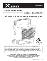
11. WIRING DIAGRAM
Figure 12. Wiring Diagram
12. SPECIFICATION
MODEL
Heat Output-BTU/Hr.
Fuel Consumption-Gal/Hr.
Fuel Tank Capacity-Gal
Electronic Pump Pressure-PSI
Volts/Hz/Amps
Phase
Product Size(L×W×H, mm)
Packing Size(L×W×H, mm)
Net Weight(Kg)
Gross Weight(Kg)
SF70DGD
70,000
0.53
4
108
120/60/1.5
1
647 × 334 × 576
580 × 385 × 605
15.7
18.0
/SF70H
CN12
SPARK PLUG
IGNITOR
L
SWITCH
VIBRATION
T4A/250Vac
FUSE
CN9
WHITE
POWER LAMP
SWITCH
PHOTO CELL
OPERATING
(LED)
CN5
WHITE
BLACK
R B
O
T
C
WHITE
(Dis 3P)
CN8
O
N P
C
MOTOR
COOLING
CN1
BLACK
(AC1)
(AC2)
CN2
CASE
EARTH
WHITE
BLUE
CN10
C/M
POWER
120Vac/60Hz
MOTOR
BLOWER
CN3
YELLOW
B/M
BLACK
CN13
CN4
WHITE
I.G
BHI
DISPLAY PCB
RPM SENSOR
BLOWER FAN
CN1 BHI
BLUE
YEL
RED
BLK
(OVERHEAT THERMOSTAT)
PUMP
ELECTRONIC
CN7
RED
E/P
LIMIT CONTROL
647
334
576

NEVER LEAVE THE HEATER
UNATTENDED WHILE BURNING!
13. EXPLODED PARTS DRAWING
NOTE : SPECIFY MODEL NUMBER AND PART NUMBER WHEN ORDERING PARTS.
13
CHAMBER FULL ASSEMBLY
BURNER FULL ASSEMBLY
8
2
9
17
1
11
12
14
15
13
21
3
7
30
28 29
31
26
35
4
5
33
27
32
34
39
22
20
16
24
23
25
38
20-1
20-2
36
19
37
20-4
20-3
20-5
6
18
10
14-2
26-3
26-6
26-5
26-4
26-12
14-7
14-1
14-8
14-4
14-3
26-14
26-13
26-15
14-6
14-5
26-11
26-9
26-7
26-2
26-1
26-18
26-17
26-22
26-25
26-24
26-21
26-19
26-16
26-20
26-10
26-8
1-4
1-6
1-3
1-5
1-7
1-1
1-2
26-23

14
NEVER LEAVE THE HEATER
UNATTENDED WHILE BURNING!
14. PARTS LIST
KEY NO. DESCRIPTION
PART NO.
SF70DGD
Quantity
1
2
3
4
5
6
7
8
9
10
11
12
13
14
15
16
17
18
19
20
20-1
20-2
20-3
20-4
20-5
21
22
23
24
25
26
26-1
1-1
1-2
1-3
1-4
1-5
1-6
1-7
26-2
26-3
26-4
26-5
26-6
26-7
26-8
Fuel Tank Assembly
Gauge Fuel Assembly
Filter Fuel Assembly
Line-Fuel
Clamp-Line
Fuel Cap Filter
Cap-Fuel
Shell Supportor
Nut-Wing
Power Cord
Nut
Cooling Motor
Bolt-RH
Cooling Fan
Spring
Shell
Flange Screw
Shell Insulator Assembly
Screw-TH1
Chamber Full Assembly
Chamber Assembly
Chamber Insulator
Ceramic Fiber
Heat Plate
Screw-TH1
Screw-TH1
Shell Ring
Screw-TH1
Safety Guard Assembly
Screw-TH2S
Burner Full Assembly
Burner Body Assembly
Burner Body
Nipple
Nozzle
Spark Plug
Bolt-HEX
Burner Blade
Bolt-PH
Insulator Plate
Bolt-TH
Sealing Pad
Diffusion Cap
Screw-RH2S
Burner Supporter
PCB Supporter
2151-0056-01
2156-0066-00
2155-0017-00
3341-0027-00
3730-0040-00
3221-0282-00
2151-0041-00
3221-0089-00
4339-0012-00
3980-0287-00
4331-0028-00
3970-0272-00
4321-0246-00
3221-0090-00
3431-0053-00
3111-0418-03
4319-0015-03
2152-0209-00
4311-0040-00
2152-0173-00
2152-0208-00
3121-0673-00
3331-0069-00
3121-0674-00
4311-0040-00
4311-0044-00
3121-0676-01
4311-0044-00
2153-0035-01
4312-0040-00
2152-0328-00
2152-0211-00
3531-0031-00
3541-0111-00
3740-0120-00
3631-0027-00
4321-0230-00
3131-0584-00
4321-0231-00
3121-0677-00
4321-0216-00
3331-0074-00
3121-0626-00
4312-0200-00
3131-0693-00
3131-0680-00
1
1
1
1
1
1
1
1
4
1
4
1
4
1
1
1
4
1
4
1
1
1
1
1
8
3
1
2
1
3
1
1
1
1
1
1
1
1
1
1
3
1
1
3
1
1
/SF70H

15
NEVER LEAVE THE HEATER
UNATTENDED WHILE BURNING!
14. PARTS LIST
KEY NO. DESCRIPTION
PART NO.
SF70DGD
Quantity
26-9
26-10
26-11
26-12
26-13
26-14
14-1
14-2
14-3
14-4
14-5
14-6
14-7
14-8
26-15
26-16
26-17
26-18
26-19
26-20
26-21
26-22
26-23
26-24
26-25
26-26
27
28
29
30
31
32
33
34
35
36
37
38
39
Screw-TH1
Card-Supporter
Spacer-Supporter
Ignitor
Screw-TH1
Blower Motor Assembly
Fan Case Assembly
Blower Motor
Bolt-BH
Blower Fan Assembly
Set Screw
Fan Cover
Screw-BH1
Photocell
Bolt-TH
Electronic Pump
Bolt-Hex
Wire-Pump
Fuel Pipe
Control PCB Assembly
Vibration Switch
Screw-RH2S
Vibration Switch Wire
Thermostat Limit
Screw-RH2S
Limit Wire
Nut-Lock
Back Cover
Inlay
Operating Switch
Wire-Operating Switch
Display PCB Assembly
Screw-RH2S
Wire-Display 3P
Screw-TH1
Handle
Bolt-TH
Heat Shield
Bolt-TH
4311-0040-00
3713-0016-00
3713-0004-00
39E0-0076-00
4311-0040-00
2154-0171-00
2154-0169-00
3970-0273-00
4321-0137-00
2154-0104-00
4323-0007-00
3131-0686-00
4311-0006-00
2153-0037-00
4321-0119-00
3970-0291-00
4321-0241-00
39D0-0996-00
3740-0171-00
215A-0093-00
39A0-0050-00
4312-0199-00
39D0-0810-00
38C0-0144-00
4312-0199-00
39D0-0998-00
4331-0031-00
3211-0031-00
3221-0107-02
39A0-0191-00
39D0-0809-00
215A-0094-00
4312-0199-00
39D0-0997-00
4311-0044-00
3231-0073-00
4321-0117-00
3121-0789-01
4321-0117-00
2
4
4
1
2
1
1
1
3
1
1
1
3
1
3
1
2
1
1
1
1
2
1
1
2
1
3
1
1
1
1
1
1
1
4
1
2
1
2
/SF70H

LIMITED WARRANTY:
This limited warranty is extended to the original retail purchaser of this Forced Air/Convection/Radiant Heater and warrants against any defect
in materials and workmanship for a period of one (1) year from the date of retail sale.GHP Group, Inc., at it’s option, will either provide
replacement parts or replace or repair the unit, when properly returned to the retailer where purchased or one of our service centers
as directed by GHP Group,Inc., within one (1) year of retail purchase. (Shipping costs, labour costs,etc. are the responsibility of the purchaser.)
DUTIES OF THE OWNER:
This heating appliance must be operated in accordance with the written instructions furnished with this heater. This warranty shall not excuse
the owner from properly maintaining this heater in accordance with the written ins
tructions furnished with this heater. A bill of sale, canceled
check or payment record must be kept to verify purchase data and establish warranty period. Original carton should be kept in case of
warranty return of unit.
WHAT IS NOT COVERED:
1. Damage resulting from use of improper fuel.
2. Damage caused by misuse or use contrary to the owners manual and safety guidelines.
3. Damage caused by a lack of normal maintenance.
4. Fuses
5. Use of non-standard parts or accessories.
6. Damage caused in transit. Freight charges on warranty parts or heaters to and from the factory shall be the responsibility of the owner.
This warranty does not imply or assume any responsibility for consequential damages that may result from the use, misuse, or the lack of
routine maintenance of this heating appliance. A cleaning fee and the cost of parts
may be charged for appliance failures resulting from lack of
maintenance. This warranty does not cover claims which do not involve defective workmanship or materials. FAILURE TO PERFORM
GENERAL MAINTENANCE (INCLUDING CLEANING) WILL VOID THIS WARRANTY.
THIS LIMITED WARRANTY IS GIVEN TO THE PURCHASER IN LIEU OF ALL OTHER WARRANTIES, EXPRESSED OR IMPLIED,
INCLUDING BUT NOT LIMITED TO THE WARRANTIES OF MERCHANTABILITY OF FITNESS FOR A PARTICULAR PURPOSE. THE
REMEDY PROVIDED IN THIS WARRANTY IS EXCLUSIVE AND IS GRANTED IN LIEU OF ALL OTHER REMEDIES. IN NO EVENT
WILL GHP GROUP, INC. BE LIABLE FOR INCIDENTAL OR CONSEQUENTIAL DAMAGES.
Some states do not allow limitations on how long an implied warranty
lasts, so the above limitation may not apply to you. Some states do not
allow the exclusion or limitation of incidental or consequential damages so the above limitation or exclusion may not apply to you.
CLAIMS HANDLED AS FOLLOWS:
1. Contact your retailer and explain the problem.
2. If the retailer is unable to resolve the problem, contact our Customer Service Dept. detailing the heater model, the problem, and proof
of date of purchase.
3. A representative will contact you. DO NOT RETURN THE HEATER TO GHP GROUP, INC. unless instructed by our Representative.
This warranty gives you
legal rights and you may also have other rights which vary from state to state.
TO REGISTER THE WARRANTY ON YOUR HEATER, PLEASE FILL OUT THIS CARD COMPLETELY
AND MAIL WITHIN 14 DAYS FROM DATE OF PURCHASE OR REGISTER ON-LINE AT www.ghpgroupinc.com
NAME: _______________________________PHONE: ( ) _________________ EMAIL: ____________________________________
ADDRESS: ___________________________CITY: ________________________ STATE: _____________________ ZIP: ___________
MODEL: ______________________________SERIAL#: _____________________ DATE PURCHASED: _________________________
DEALER PURCHASED FROM: _________________________________________ TYPE OF STORE: __________________________
CITY & STATE WHERE PURCHASED: ___________________________________ PRICE PAID: _______________________________
Please Take 1 Minute To Give Us Your Answers To The Following Questions.
Who primarily decided this purchase? Male Female 18-24 25-39 40-59 60 and over of age?
Do you own any other portable heaters?
Yes No If yes, type ______________________ brand ____________________________
How do you intend to use your new heater?
Construction Site Farm Warehouse/Commercial Garage/Outbuilding Other
How did you become aware of this heater?
In-Store Display Newspaper Ad Magazine Ad Friend/Relative
TV Commercial Store Salesperson Other ____________________________________________________________________
What made you select this heater?
Style Size/Portability Price Package Brand Other __________________________
Do you:
Own Rent Would you recommend this heater to a friend? Yes No
Please give us your comments _____________________________________________________________________________________
THANK YOU FOR COMPLETING THIS FORM!
Information will be held
Warranty

WARRANTY REGISTRATION
days of date of purchase. You can also register your warranty on the internet at
www.ghpgroupinc.com. Complete the entire serial number. Retain this portion of the card
for your records.
Place
Postage
Stamp
Here
SAVE THIS CARD!
GHP Group, Inc.
6440 W Howard St
Niles, IL 60714-3302
Tel: (877) 447-4768
www.ghpgroupinc.com
GHP Group, Inc.
6440 W Howard St
Niles, IL 60714-3302

PRODUCTOS PARA INTERIORES/EXTERIORES
CALEFACTORE DE AIRE FORZADO
PORTÁTILES DE KEROSENE
“MANUAL DEL USUARIO E INSTRUCCIONES
DE FUNCIONAMIENTO”
Antes de utilizar por primera vez este calefactor, lea muy atentamente el
MANUAL DEL USUARIO. Este MANUAL DEL USUARIO ha sido
diseñado para enseñarle la forma correcta de ensamblar, mantener, guardar y,
Conserve este manual para consultarlo cuando sea necesario.
CONSUMIDOR: conserve este manual para consultarlo cuando sea necesario.
¿Dudas, problemas, piezas faltantes? Antes de volver a la tienda, llame a nuestro Departamento de
Atención al Cliente al 877-447-4768, de lunes a viernes de 8:30 a 16:30 (hora central estándar)
o escriba a customerservice@ghpgroupinc.com
CUMPLE CON UL733 Y
CAN/CSA/B140.0-03 Y
CSA B140.8-1967
MODEL: SF70DGD MODEL: SF70H
IMSFDG - KDS

RESIDENTES DE MASSACHUSETTS:
que se utilice total o parcialmente para vivienda. El uso de este dispositivo de calefacción en Massachusetts requiere el permiso del
departamento local de bomberos (M.E.L.C. 148, sección 10A).
RESIDENTES DE CANADÁ: Este calefactor se debe utilizar de acuerdo con las autoridades competentes y la norma B139 de la CSA.
RESIDENTES DE LA CIUDAD DE NUEVA YORK: Solo para ser utilizado en obras en construcción de acuerdo con los códigos
de Nueva York (NYCFD).
1
PELIGRO: EL USO INCORRECTO DE ESTE CALEFACTOR PUEDE OCASIONAR LESIONES
GRAVES O LA MUERTE POR QUEMADURAS, INCENDIO, EXPLOSIÓN,
DESCARGA ELÉCTRICA Y/O INTOXICACIÓN POR MONÓXIDO DE CARBONO.
ADVERTENCIAS:
1. RIESGO DE CONTAMINACIÓN DEL AIRE EN INTERIORES
2. RIESGO DE QUEMADURAS/INCENDIO/EXPLOSIÓN
3. RIESGO DE DESCARGA ELÉCTRICA
• Utilice este calefactor solo en áreas bien ventiladas. Mantenga una abertura para que ingrese aire fresco del exterior de al
menos tres pies cuadrados (2800 cm cuadrados) por cada 100 000 BTU/h según las condiciones nominales de funcionamiento del calefactor.
• Las personas con problemas respiratorios deben consultar a un médico antes de utilizar el calefactor.
• Intoxicación por monóxido de carbono: Los signos tempranos de intoxicación por monóxido de carbono se asemejan a
la gripe con dolores de cabeza, mareos y/o náuseas. Si tiene estos signos, es posible que el calefactor no esté funcionando
correctamente. ¡Tome aire fresco inmediatamente! Haga reparar el calefactor. Algunas personas se ven más afectadas por el
monóxido de carbono que otras. Por ejemplo, las mujeres embarazadas; las personas con enfermedades cardíacas o pulmonares,
o anemia; las personas que están bajo los efectos del alcohol; o las personas que están a alturas elevadas.
• Nunca utilice este calefactor en áreas habitables o para dormir.
• NUNCA utilice combustibles que no sean kerosene 1-K, diesel/fueloil n.º 1/n.º 2, combustibles JET A o JP-8 en este calefactor.
• NUNCA utilice combustible como gasolina, benceno, solventes para pintura ni otros compuestos del aceite en este calefactor.
(RIESGO DE INCENDIO O EXPLOSIÓN)
• NUNCA
• Nunca recargue el tanque de combustible del calefactor mientras el calefactor está funcionando o si todavía está caliente.
•
.
• Utilice solo un enchufe y un cable prolongador conectados a tierra de tres patas.
• SIEMPRE instale el calefactor de manera que no esté directamente expuesto a rociado con agua, lluvia, goteo de agua ni viento.
• SIEMPRE desenchufe el calefactor cuando no está en uso.
• Distancias mínimas: Salida: 8 pies (250 cm) / laterales, parte superior y posterior: 4 pies (125 cm)
• NUNCA bloquee la entrada de aire (parte posterior) o la salida de aire (parte frontal) del calefactor.
• NUNCA coloque conductos delante o detrás del calefactor.
• NUNCA mueva, manipule ni repare un calefactor caliente, enchufado o en funcionamiento.
• NUNCA traslade el calefactor con combustible en el tanque.
• Cuando se utiliza con un termostato opcional o si está equipado con un termostato, el calefactor puede encenderse
en cualquier momento.
• SIEMPRE
• SIEMPRE asegúrese de que no haya niños ni animales cerca del calefactor.
• El almacenamiento de combustible a granel debe estar como mínimo a 25 pies de calefactores, faros, generadores portátiles u
otras fuentes de ignición. El almacenamiento de combustible debe realizarse de acuerdo con lo estipulado por las autoridades
locales, estatales o federales competentes.
NUNCA DEJE DESATENDIDO EL CALEFACTOR
MIENTRAS ESTÁ ENCENDIDO.
PRECAUCIÓN:
Caliente durante el funcionamiento. No lo toque.
Asegúrese de que no haya niños, ropa ni combustibles
cerca del calefactor.
ADVERTENCIA: Este producto y el combustible utilizado para poner en funcionamiento
este producto (kerosén o otros combustibles aprobados), y los productos de la combustión de tal
combustible, pueden exponerlo a sustancias químicas como el benceno que, según el estado de California,
puede provocar cáncer y daños reproductivos.
Para obtener más información, visite www.p65Warnings.ca.gov
1/68