MULTIPLEX Funcub Xl Le manuel du propriétaire
- Catégorie
- Jouets télécommandés
- Taper
- Le manuel du propriétaire
Ce manuel convient également à

# 26 4331
Bauanleitung 2 ... 12
Building instructions 13 ... 23
Notice de construction 24 ... 46
Instruzioni di montaggio 47 ... 57
Instrucciones de montaje 58 ... 68
69-71
D
F
GB
I
ES
© Copyright by MULTIPLEX Modellsport GmbH & Co. KG 2015 Version 1.0
Ersatzteile
Replacement parts
Pièces de rechanges
Parti di ricambio
Repuestos
Abbildungen
Illustrations
Illustrations
Illnstrazioni
Iiustraciónes
31-42
RR
# 21 4331

Seite 2
Sicherheitshinweise für MULTIPLEX-Flugmodelle
Das Modell ist KEIN SPIELZEUG im üblichen Sinne.
Mit Inbetriebnahme des Modells erklärt der Betreiber, dass er den Inhalt der Betriebsanleitung, besonders zu Sicher-
heitshinweisen, Wartungsarbeiten, Betriebsbeschränkungen und Mängel kennt und inhaltlich nachvollziehen kann.
Dieses Modell darf nicht von Kindern unter 14 Jahren betrieben werden. Betreiben Minderjährige das Modell unter der
Aufsicht eines, im Sinne des Gesetzes, fürsorgepfl ichtigen und sachkundigen Erwachsenen, ist dieser für die Umsetzung
der Hinweise der BETRIEBSANLEITUNG verantwortlich.
DAS MODELL UND DAZUGEHÖRIGES ZUBEHÖR MUSS VON KINDERN UNTER 3 JAHREN FERNGEHALTEN
WERDEN! ABNEHMBARE KLEINTEILE DES MODELLS KÖNNEN VON KINDERN UNTER 3 JAHREN VERSCHLUCKT
WERDEN. ERSTICKUNGSGEFAHR!
Beim Betrieb des Modells müssen alle Warnhinweise der BETRIEBSANLEITUNG beachtet werden. Die Multiplex Mo-
dellsport GmbH & Co. KG ist nicht haftungspfl ichtig für Verluste und Beschädigungen jeder Art, die als Folge falschen
Betriebes oder Missbrauches dieses Produktes, einschließlich der dazu benötigten Zubehörteile entstehen. Dies beinhaltet
direkte, indirekte, beabsichtigte und unabsichtliche Verluste und Beschädigungen und jede Form von Folge-schäden.
Jeder Sicherheitshinweis dieser Anleitung muss unbedingt befolgt werden und trägt unmittelbar zum sicheren Betrieb
Ihres Modells bei. Benutzen Sie Ihr Modell mit Verstand und Vorsicht, und es wird Ihnen und Ihren Zuschauern viel
Spaß bereiten, ohne eine Gefahr darzustellen. Wenn Sie Ihr Modell nicht verantwortungsbewusst betreiben, kann dies
zu erheblichen Sachbeschädigungen und schwerwiegenden Verletzungen führen. Sie alleine sind dafür verantwortlich,
dass die Betriebsanleitungen befolgt und die Sicherheitshinweise in die Tat umgesetzt werden.
Bestimmungsgemäße Verwendung
Das Modell darf ausschließlich im Hobbybereich verwendet werden. Jede weitere Verwendung darüber hinaus ist nicht
erlaubt. Für Schäden oder Verletzungen an Menschen und Tieren aller Art haftet ausschließlich der Betreiber des Modells
und nicht der Hersteller.
Zum Betrieb des Modells darf nur das von uns empfohlene Zubehör verwendet werden. Die empfohlenen Komponenten
sind erprobt und auf eine sichere Funktion passend zum Modell abgestimmt. Werden andere Komponenten verwendet
oder das Modell verändert, erlöschen alle Ansprüche an den Hersteller bzw. den Vertreiber.
Um das Risiko beim Betrieb des Modells möglichst gering zu halten, beachten Sie folgende Punkte:
l Das Modell wird über eine Funkfernsteuerung gelenkt. Keine Funkfernsteuerung ist sicher vor Funkstörungen.
Solche Störungen können dazu führen, dass Sie zeitweise die Kontrolle über Ihr Modell verlieren. Deshalb müs-
sen Sie beim Betrieb Ihres Modells zur Vermeidung von Kollisionen immer auf große Sicherheitsräume in allen
Richtungen achten. Schon beim kleinsten Anzeichen von Funkstörungen müssen Sie den Betrieb Ihres Modells
einstellen!
l Sie dürfen Ihr Modell erst in Betrieb nehmen, nachdem Sie einen kompletten Funktionstest und einen Reichwei-
tentest, gemäß der Anleitung Ihrer Fernsteuerung, erfolgreich ausgeführt haben.
l Das Modell darf nur bei guten Sichtverhältnissen gefl ogen werden. Fliegen Sie nicht in Richtung Sonne, um
nicht geblendet zu werden, oder bei anderen schwierigen Lichtverhältnissen.
l Ein Modell darf nicht unter Alkohol-Einfl uss oder Einfl uss von anderen Rauschmitteln oder Medikamenten be-
trieben werden, die das Wahrnehmungs- und Reaktionsvermögen beeinträchtigen.
l Fliegen Sie nur bei Wind- und Wetterverhältnissen, bei denen Sie das Modell sicher beherrschen können. Be-
rücksichtigen Sie auch bei schwachem Wind, dass sich Wirbel an Objekten bilden, die auf das Modell Einfl uss
nehmen können.
l Fliegen Sie nie an Orten, an denen Sie andere oder sich selbst gefährden können, wie z.B. Wohngebiete, Über-
landleitungen, Straßen und Bahngleise.
l Niemals auf Personen und Tiere zufl iegen. Anderen Leuten dicht über die Köpfe zu fl iegen ist kein Zeichen für
wirkliches Können, sondern setzt andere Leute nur ein unnötiges Risiko aus. Weisen Sie auch andere Piloten
in unser aller Interesse auf diese Tatsache hin. Fliegen Sie immer so, dass weder Sie noch andere in Gefahr
kommen. Denken Sie immer daran, dass auch die allerbeste Fernsteuerung jederzeit gestört werden kann. Auch
langjährige, unfallfreie Flugpraxis ist keine Garantie für die nächste Flugminute.
D

Seite 3
Restrisiken
Auch wenn das Modell vorschriftsmäßig und unter Beachtung aller Sicherheitsaspekten betrieben wird, besteht immer
ein gewisses Restrisiko.
Eine Haftpfl ichtversicherung ist daher obligatorisch. Falls Sie in einen Verein oder Verband eintreten, können Sie diese
Versicherung dort abschließen. Achten Sie auf ausreichenden Versicherungsschutz (Modellfl ugzeug mit Antrieb). Halten
Sie Modelle und Fernsteuerung immer absolut in Ordnung.
Folgende Gefahren können im Zusammenhang mit der Bauweise und Ausführung des Modells auftreten:
l Verletzungen durch die Luftschraube: Sobald der Akku angeschlossen ist, ist der Bereich um die Luftschraube
freizuhalten. Beachten Sie auch, dass Gegenstände vor der Luftschraube angesaugt werden können oder Ge-
genstände dahinter weggeblasen werden können. Das Modell kann sich in Bewegung setzen. Richten Sie es
daher immer so aus, dass es sich im Falle eines ungewollten Anlaufen des Motors nicht in Richtung anderer
Personen bewegen kann. Bei Einstellarbeiten, bei denen der Motor läuft oder anlaufen kann, muss das Modell
stets von einem Helfer sicher festgehalten werden.
l Absturz durch Steuerfehler: Kann dem besten Piloten passieren, deshalb nur in sicherer Umgebung fl iegen; ein
zugelassenes Modellfl uggelände und eine entsprechende Versicherung sind unabdingbar.
l Absturz durch technisches Versagen oder unentdeckten Transport- oder Vorschaden. Die sorgfältige Überprüfung
des Modells vor jedem Flug ist ein Muss. Es muss jedoch immer damit gerechnet werden, dass es zu Material-
versagen kommen kann. Niemals an Orten fl iegen, an denen man Anderen Schaden zufügen kann.
l Betriebsgrenzen einhalten. Übermäßig hartes Fliegen schwächt die Struktur und kann entweder zu plötzlichem
Materialversagen führen, oder bei späteren Flügen das Modell aufgrund von „schleichenden“ Folgeschäden
abstürzen lassen.
l Feuergefahr durch Fehlfunktion der Elektronik. Akkus sicher aufbewahren, Sicherheitshinweise der Elektro-
nikkomponenten im Modell, des Akkus und des Ladegerätes beachten, Elektronik vor Wasser schützen. Auf
ausreichende Kühlung bei Regler und Akku achten.
Die Anleitungen unserer Produkte dürfen nicht ohne ausdrückliche Erlaubnis der Multiplex Modellsport GmbH
& Co. KG (in schriftlicher Form) - auch nicht auszugsweise in Print- oder elektronischen Medien reproduziert
und / oder veröffentlicht werden.
D

Seite 4
Machen Sie sich mit dem Bausatz vertraut!
MULTIPLEX – Modellbaukästen unterliegen während der Produktion einer ständigen Materialkontrolle. Wir hoffen, dass
Sie mit dem Baukasteninhalt zufrieden sind. Wir bitten Sie jedoch, alle Teile (nach Stückliste) vor Verwendung zu prü-
fen, da bearbeitete Teile vom Umtausch ausgeschlossen sind. Sollte ein Bauteil einmal nicht in Ordnung sein, sind
wir nach Überprüfung gern zur Nachbesserung oder zum Umtausch bereit. Bitte senden Sie das Teil, bitte ausreichend
frankiert, an unsere Modellbauabteilung und fügen Sie unbedingt den Kaufbeleg und eine kurze Fehlerbeschreibung bei.
Wir arbeiten ständig an der technischen Weiterentwicklung unserer Modelle. Änderungen des Baukasteninhalts in
Form, Maß, Technik, Material und Ausstattung behalten wir uns jederzeit und ohne Ankündigung vor. Bitte haben Sie
Verständnis dafür, dass aus Angaben und Abbildungen dieser Anleitung keine Ansprüche abgeleitet werden können.
Achtung!
Ferngesteuerte Modelle, insbesondere Flugmodelle, sind kein Spielzeug im üblichen Sinne. Ihr Bau und Betrieb
erfordert technisches Verständnis, ein Mindestmaß an handwerklicher Sorgfalt sowie Disziplin und Sicherheits-
bewusstsein. Fehler und Nachlässigkeiten beim Bau und Betrieb können Personen- und Sachschäden zur Folge
haben. Da der Hersteller keinen Einfl uss auf ordnungsgemäßen Zusammenbau, Wartung und Betrieb hat, weisen
wir ausdrücklich auf diese Gefahren hin.
Warnung:
Das Modell hat, wie jedes Flugzeug, statische Grenzen! Sturz" üge und unsinnige Manöver im Unverstand können zum
Verlust des Modells führen. Beachten Sie: In solchen Fällen gibt es von uns keinen Ersatz. Tasten Sie sich also vorsichtig
an die Grenzen heran. Das Modell ist auf den von uns empfohlenen unseren Antrieb ausgelegt, kann aber nur einwandfrei
gebaut und unbeschädigt den Belastungen standhalten.
Benötigtes Zubehör für das Modell FunCub XL:
2x Li-BATT FX 3/1-3200 (M6) (KIT+RR) Best.-Nr. # 157371
1x Antriebssatz FunCub XL (nur KIT) Best.-Nr. # 332610
1x Empfänger RX-7-DR light M-LINK 2,4 GHz (KIT+RR) Best.-Nr. # 55810
6x Servo HS-225 BB (nur KIT) Best.-Nr. # 112225
2x Servo-Verlängerungskabel 600mm (nur KIT) Best.-Nr. # 85032
4x Servo-Verlängerungskabel 300mm (nur KIT) Best.-Nr. # 85031
2x Servo-Verlängerungskabel 150mm (nur KIT) Best.-Nr. # 85019
1x Zacki ELAPOR 20g (RR) Best.-Nr. # 852727
2x Zacki ELAPOR 20g (KIT) Best.-Nr. # 852727
Optionales Zunehör für das Modell FunCub XL:
Schwimmerset FunCub XL Best.-Nr. # 733098
Fallschirmspringer Alfred Best.-Nr. # 852004
POWER-MULTIlight, 5 LEDs Best.-Nr. # 73030
Empfänger RX-12-DR compact M-LINK 2,4 GHz Best.-Nr. # 55821
Servo HS-225 BB für Schleppkupplung Best.-Nr. # 112225
Servo HS-225 BB für Abwurfschacht Best.-Nr. # 112225
Sender Royal SX Best.-Nr. # 3540 0/1/2/3
Combo MULTIcharger LN-3008 EQU mit Netzteil AC/DC 230V/12V 5,0A Best.-Nr. # 92545
Ladekabel (M6) für MULTIcharger LN-3008 EQU Best.-Nr. # 92516
D

Seite 5
Wichtiger Hinweis
Dieses Modell ist nicht aus Styropor ™! Daher sind Verklebungen mit Weißleim, Polyurethan oder Epoxy nicht möglich.
Diese Kleber haften nur ober" ächlich und platzen im Ernstfall einfach ab. Verwenden Sie nur Cyanacrylat-/Sekunden-
kleber mittlerer Viskosität, vorzugsweise Zacki -ELAPOR® # 85 2727, der für ELAPOR® Partikelschaum optimierte und
angepasste Sekundenkleber. Bei Verwendung von Zacki-ELAPOR® können Sie auf Kicker oder Aktivator weitgehend
verzichten. Wenn Sie jedoch andere Kleber verwenden, und auf Kicker/Aktivator nicht verzichten können, sprühen Sie
aus gesundheitlichen Gründen nur im Freien. Vorsicht beim Arbeiten mit allen Cyanacrylatklebern. Diese Kleber härten
u.U. in Sekunden, daher nicht mit den Fingern und anderen Körperteilen in Verbindung bringen. Zum Schutz der Augen
unbedingt Schutzbrille tragen! Von Kindern fernhalten! An einigen Stellen ist es auch möglich Heißkleber zu verwenden.
Wir weisen in der Anleitung ggf. darauf hin!
Arbeiten mit Zacki ELAPOR®
Zacki ELAPOR® wurde speziell für die Verklebung für unsere Schaummodelle aus ELAPOR® entwickelt.
Um die Verklebung möglichst optimal zu gestalten, sollten Sie folgende Punkte beachten:
• Vermeiden Sie den Einsatz von Aktivator. Durch ihn wird die Verbindung deutlich geschwächt.
Vor allem bei groß" ächiger Verklebung empfehlen wir, die Teile 24 h trocken zu lassen.
• Aktivator ist lediglich zum punktuellen Fixieren zu verwenden. Sprühen Sie nur wenig Aktivator einseitig auf.
Lassen Sie den Aktivator ca. 30 Sekunden ablüften.
• Für eine optimale Verklebung rauen Sie die Ober" äche mit einem Schleifpapier (320 er Körnung) an.
Krumm - gibt es eigentlich nicht. Falls mal etwas z.B. beim Transport verbogen wurde, kann es wieder gerichtet
werden. Dabei verhält sich ELAPOR® ähnlich wie Metall. Etwas überbiegen, das Material federt ein Stück zurück
und behält dann aber die Form. Alles hat natürlich auch seine Grenzen - übertreiben Sie also nicht!
Krumm - gibt es schon! Wenn Sie Ihr Modell lackieren wollen, reiben Sie die Ober" äche leicht mit MPX Primer #
602700 ab, so als wollten Sie das Modell putzen. Die Lackschichten dürfen keinesfalls zu dick oder ungleichmäßig
aufgetragen werden, sonst verzieht sich das Modell. Es wird krumm, schwer und oft sogar unbrauchbar! Mattlacke
bringen optisch das beste Ergebnis.
Technische Daten:
Spannweite: 1700 mm
Länge über alles: 1200 mm
Fluggewicht: 2850 g
Gesamt" ächeninhalt: 51 dm²
Gesamt" ächenbelastung: 56 g/dm²
Steuerkanäle: 7-10
RC-Funktionen: Seitenruder, Höhenruder, Querruder, Landeklappen, Motor,
Optional Schleppkupplung, Optional Abwurfschacht,
Optional Positionslichter und Landescheinwerfer
Flugzeit: ca. 6 min (6S ~3300 mAh)
Hinweis: Bildseiten aus der Mitte der Bauaneitung heraustrennen!

Seite 6
3. Montage der Motor- und Kabinenhaube (KIT)
Nehmen Sie nun die Motorhaube 7 und kleben Sie mit Zacki die
Auspuffverkleidung „vorne“ 28 an die Unterseite.
Abb 13 + 14
Die Motorhaube wird später mit Magneten am Rumpf gehalten.
Kleben Sie sechs Stück der Magnete 34 an die de! nierten Stellen
an Motorhaube 7 und an die Rumpfvorderseite.
!ACHTUNG!: Achten Sie auf die Ausrichtung der Magneten
zueinander. Zusammengehörende Magneten dürfen sich nicht
abstoßen" Setzen Sie die Motorhaube erst auf, wenn der Kleber
getrocknet ist"
Abb. 15 – 17
Kleben Sie nun die beiden Canopy Lock Zapfen 74 in die vorge-
fertigten Schlitze der Kabinenhaube 6 mit Zacki ein.
Abb. 18
4. Motoreinbau (KIT)
Schrauben Sie das Motorkreuz mit den vier beiliegenden Kreuz-
schlitzschrauben am Motor fest. Verwenden Sie dabei jeweils
einen Tropfen Schraubensicherungslack.
Abb. 19
Befestigen Sie bei abgenommener Motorhaube den Motor am
Rumpf. Dazu platzieren Sie das Motor-Montagekreuz 131 (Kunst-
stoff) zwischen dem schon montierten Motorkreuz und dem M-
Frame Motorspant. Mit jeweils vier Motorbefestigungsschrauben
132 (M3x12mm) und U-Scheiben 133 (innen Ø 3mm) wird der
Motor verschraubt. Anschließend kann die Motorhaube wieder
aufgesetzt werden.
Abb. 20 + 21
5. Montage des Hauptfahrwerks (KIT+RR)
Befestigen Sie zunächst mit je zwei Kreuzschlitzschrauben 37
(M3x6mm) den L-Verstrebungshalter 36 von unten am Haupt-
fahrwerksbügel 35. Anschließend montieren Sie das Hauptfahr-
werksrad 39 mit der Achsschraube 40 (M6x45mm) einer Mutter
89 (M6) und einer Stoppmuttern 41 (M6). Achten Sie darauf, dass
sich das Rad nach dem Anziehen noch frei drehen kann. Auf der
anderen Seite des Fahrwerks gehen Sie analog vor.
Abb. 22
Schrauben Sie das zusammengebaute Fahrwerk mit vier Fahr-
werksbefestigungsschrauben 42 (M3x20mm) an den M-Frame.
Die Laschen zur Strebenbefestigung müssen sich in Flugrichtung
hinten be! nden"
Abb. 23
6. Montage des Spornfahrwerks (KIT+RR)
Beim Zusammenbau des Spornfahrwerks nehmen Sie zunächst
den Sporn 47 und schieben das untere Spornlager 48 durch die
Bohrung. Auf dieses stecken Sie dann mit etwas Zacki von oben
das obere Spornlager 46 auf. Nun wird von unten der Spornlager-
bolzen 49 bis zum Anschlag ins Lager gesteckt. Dieser wird mit
einer Kreuzschlitzschraube 45 (M3x6mm) durch den Lenkhebel
44 und den eingesteckten Mitnehmer 43 gesichert. Achten Sie
darauf, dass die Schraube auf der gefrästen Plan# äche den
Bolzen klemmt.
Auf der freien Seite des Lagerbolzens be! ndet sich eine Gewinde-
bohrung M3. Schieben Sie den Heckradhalter 50 auf den Bolzen
auf (Vierkant) und schrauben Sie ihn mit der Kreuzschlitzschraube
55 (M3x10mm) und einer U-Scheibe 54 (innen Ø 3mm) fest.
Abschließend montieren Sie noch das Spornrad 51 mit der
Spornradachse 52 (M2x22mm), zwei Muttern 38 (M2,5) als
Abstandshalter zwischen Rad und Heckradhalter, und einer
Stoppmutter 53 (M2).
Abb. 24
Herzlichen Glückwunsch zu Ihrer neuen Multiplex
FunCub XL
Zum Bau des Modells benötigen Sie folgendes Werkzeug:
• 2x Zacki-Elapor # 85 2727
• Heißklebepistole
• Großen und kleinen Kreuzschlitzschraubendreher
• Cuttermesser
• Spitzzange
• Inbusschlüssel 1,5
• 6er Gabelschlüssel
• 10er Gabelschlüssel
• 13er Gabelschlüssel
Bei Einbau vom POWER-MULTIlight zusätzlich:
• 2 M6 Stecker # 8 5213
• 2 M6 Buchsen # 8 5214
• Lötkolben
• Lötzinn
Vor dem Bau:
Überprüfen Sie die gelieferten Teile auf Ihre Vollständigkeit mittels
der Stückliste auf Seite 31 Abb. 01 + 02
1. Vorbereiten der Rumpfhälften und Einbau der Servos (KIT)
Kleben Sie mit Zacki den bereits vormontierten M-Frame 30 in
die rechte Rumpfhälfte 5 ein. Anschließend kleben Sie den M-
Frame Schwimmerhalter 31, die beiden Clip-Scharniere „A“ 71,
den Canopy Lock Halter 73 und die Schleppkupplung 75 an die
vorgesehenen Positionen.
Abb. 03 + 04
Der zweite Canopy Lock Halter 73 wird analog dazu in die linke
Rumpfhälfte 4 eingeklebt.
Stellen Sie das Höhenruderservo (HiTec HS-225BB # 11 2225)
mit Ihrer Fernsteueranlage mittig ein und befestigen Sie dann mit
der beiliegenden Schraube den Servohebel so, dass er nach links
zeigt, wenn Sie die Schrift auf dem Aufkleber lesen können. Ste-
cken Sie das Servo-Verlängerungskabel 600mm (# 8 5032) an und
sichern Sie es mit etwas Klebeband, damit es sich im Flug nicht
ausstecken kann. Montieren Sie das Höhenruderservo (Kabel
zeigen in Flugrichtung) in der Aussparung an der rechten Rumpf-
hälfte 5 und verkleben Sie es an seinen Laschen mit Heißkleber.
Abb. 05
Montieren Sie das Seitenruderservo (HiTec HS-225BB # 11 2225)
wie zuvor beschrieben – jedoch mit umgekehrter Ausrichtung des
Hebels – und kleben Sie es nach Anstecken und Sichern des
Servo-Verlängerungskabels 600mm (# 8 5032) mit Heißkleber
an den Laschen in die Aussparung an der linken Rumpfhälfte 4.
Abb. 06
2. Verkleben der Rumpfhälften und Anbringen der Zusatzteile
(KIT)
Vor dem Verkleben der Rumpfhälften 4 + 5 stecken Sie die
beiden Teile trocken zusammen. Wenn alles zusammenpasst,
tragen Sie Zacki auf eine Rumpfhälfte auf und verkleben Sie
alles miteinander.
Abb. 07 + 08
Nun kleben Sie die Luftauslasszierden 24 + 25, die Motorhau-
benaufsätze 26 + 27 und die Rumpfanschlussrippe „L“ 76 und
Rumpfanschlussrippe „R“ 77 an ihre Positionen.
Abb. 09 + 10
Drehen Sie jetzt den Rumpf auf den Rücken und kleben Sie die
Auspuffverkleidung „hinten“ 29 an die Rumpfunterseite. Anschlie-
ßend kleben Sie die Cargodoor-Lager „A“ 32 und „B“ 33, sowie
den Spornhalter 56 ein.
Abb. 11 + 12

Seite 7
Der gebaute Sporn wird dann mit zwei Spornbefestigungsschrau-
ben 57 (M3x20mm) am Spornhalter 56 mit dem Rumpf verbunden.
Abb. 25
7. Montage der Tragfl ächen (KIT)
Kleben Sie je ein Holmrohr 123/124 in die beiden Flächenhälften
8 und 9 in die dafür vorgesehene Position. Wischen Sie ggf. mit
einem Papiertuch überquellenden Klebstoff ab, damit später die
obere Holmabdeckung bündig anliegt.
Kleben Sie nun die hintere Holmabdeckung 12 und 13 ein und
achten Sie darauf, dass kein Klebstoff ins Innere quillt. Nehmen
Sie die Landeklappen 14 und 15 zur Hand und klipsen Sie die
Offsetscharniere aus den Teilen 64 und 65 sowie die Klappen-
ruderhörner aus den Teilen 63 und 64 zusammen. Kleben Sie
die Offsetscharniere und die Ruderhörner in die Flächen und
Landeklappen.
Abb. 27+28
Kleben Sie nun die Strebenhalter 98, sowie die Ruderhörner der
Querruder 61 in die Tragfl ächen ein.
Abb. 29+30
Stellen Sie die Querruderservos (HiTec HS-225BB # 11 2225)
mit Ihrer Fensteueranlage mittig ein und schrauben Sie das Ser-
vohorn auf. Kleben Sie das Servo mit etwas Heißkleber an den
Befestigungslaschen in die Tragfl äche ein. Schrauben Sie den
Gestängeanschluss 66 mit der U-Scheibe 69 (innen Ø 2mm) und
der Mutter 70 (M2) an die Ruderhörner 61 und achten Sie darauf,
dass der Gestängeanschluss kein Spiel hat, sich aber leicht drehen
lässt. Sichern Sie die Mutter 70 mit etwas Zacki. Verlängern Sie
das Servokabel mit der Servoverlängerung # 8 5019 (150mm) und
legen Sie das Kabel in den Schacht.
Verbinden Sie nun mit den Gestängen die Servos und die Ruder-
hörner und justieren Sie das Gestänge so, dass bei Neutralposition
des Servos die Ruderklappe auch neutral steht. Ziehen Sie die
Madenschraube 68 (M3x3mm) fest an.
Abb. 31+32
Schließen Sie die Landeklappenservos an Ihre Fernsteueranlage
an und fahren Sie die Servos in die Endposition (Eingefahren).
Schrauben Sie das Servohorn so an, dass sich bei eingefahrener
Landeklappe die Anlenkung 117 mit dem Servohebel verkniet und
das Servo nicht unter Last steht, wie auf Abbildung 33 ersichtlich.
Schrauben Sie wie im Arbeitsschritt zuvor den Gestängeanschluss,
bestehend aus den Teilen 66 und 68-70, an das Ruderhorn und
hängen Sie das Gestänge 117 gemäß der Abbildung 34 ein.
Überprüfen Sie die Anlenkung mehrmals, bevor Sie das Servo
an den Laschen mit etwas Heißkleber in die Aussparung der
Tragfl ächen kleben. Justieren Sie die Landeklappen, wenn das
Servo fest eingeklebt ist und ziehen Sie die Madenschrauben 68
(M3x3mm) fest an.
Abb. 33-35
8. Einbau der Beleuchtung POWER-MULTIlight in die Trag-
fl ächen (KIT+RR)
Das Modell FunCub XL ist für den Einbau des POWER-MULTIlights
# 7 3030 vorgesehen. Bei der RR-Version liegen bereits Kabel in
den Flächen.
Legen Sie eine weiße LED an die vorgesehene Position für den
Landescheinwerfer auf die Fläche, und das Kabel in den Kanal-
bzw. entlang des Kanals auf die Tragfl äche und schneiden Sie
es an der Wurzelrippe so ab, dass Sie noch ca. 10cm Luft zum
Anlöten eines M6-Zentralsteckers haben.
Wollen Sie sich sie Option für eine Spätere Beleuchtung vorbe-
halten, dann empfehlen wir, in diesem Bauabschnitt Kabel oder
Schnüre zum späteren Durchziehen von Kabeln einzubauen.
Zum Befestigen der LED nehmen Sie am besten wenig Zacki.
Wenn Sie keine Beleuchtung einbauen und auch wenn die LED
positioniert ist wird als nächstes die durchsichtige LED-Lande-
scheinwerferabdeckung 96 mit wenig Klebstoff am Rand an die
Tragfl ächen geklebt. Abb. 36
Gehen Sie beim Einbau der Antikollisionslichter und der Blitzlichter
an den Tragfl ächenaußenseiten analog zu den Landescheinwer-
fern vor und kleben Sie Teil 95 an die Randbögen der Tragfl ächen.
Schrauben Sie die Positionslichtabdeckungen 93+94 mit den
Schrauben 97 (1,7x14mm) an die Halter 95.
Abb. 37
9. Verkabelung der Tragfl ächen (KIT+RR)
Kleben Sie die Rahmen für die Steckerboxen 82+83 in die Trag-
fl ächen ein und legen Sie die Kabel gemäß Abb. 39 in diese ein.
Kleben Sie nun die vordere Holmabdeckung 10+11 in die Trag-
fl äche ein. Abb. 40
Kleben Sie mit wenig Zacki die Steckerhalter 86+87 in die Rah-
men 82+83, gemäß Abb. 41. Schrauben Sie Teil 88 mit den
Schrauben 90 (2,4x8mm) so darüber, dass Stecker und Kabel
der Beleuchtung dazwischen liegen. Die Stecker müssen de" niert
eingeklemmt sein.
Abb. 41+42
Löten Sie einen M6-Stecker mit etwa 5cm Abstand zur Wurzelrip-
pe an die Beleuchtungskabel und versiegeln Sie die Lötung mit
Heißkleber, so dass keine blanken Kontakte mehr offen liegen
(alternativ können Sie auch Schrumpfschlauch nehmen). Achten
Sie bei der Polung darauf, dass die Trag! ächenseite und die Ge-
genseite im Rumpf die jeweils von Ihnen richtige LED ansteuern.
! Achtung! : Da die LED´s des POWER-MULTIlights mit unter-
schiedlichen Spannungen und Blinkfrequenzen laufen, ist es nicht
möglich Kabel (+ oder -) zusammenzulegen.
Abb. 43+44
Verschließen Sie die Kabelboxen mit den Abdeckungen 84+85
und den Schrauben 91 (2,4x8mm).
Abb. 45+46
10. Montage der Flächenverschraubung (KIT)
Schieben Sie die Muttern 81 (M5) in die Flächenanschlüsse 78+79
und sichern Sie diese anschießend mit einem Tropfen Zacki.
Achten Sie darauf, dass das Gewinde nicht verklebt. Kleben Sie
die Flächenanschlüsse an die Trag! ächen.
Abb.47-48
11. Montage der Tragfl ächenverstrebung (KIT)
Setzen Sie in die beiden Teile des unteren Strebenanschlusses
106 + 107 das Aluteil 103 ein. Verschrauben Sie dann diese Teile
mit den Schrauben 108 (M2x8mm) und den Muttern 110 (M2).
Bitte beachten Sie, dass die Pfeile auf den Teilen 106 und 107 in
Flugrichtung zeigen. Der Optik wegen sollten sich die Schrauben
auf der Oberseite be" nden.
Schrauben Sie nun den Rumpf-Strebenanschluss 104 auf. In die
jetzt noch freien Bohrungen stecken Sie die Hauptstreben aus CFK
111 und kleben diese mit Zacki fest. Zur Sicherheit verschrauben
Sie den Strebenanschluss zwischen den CFK-Teilen noch mit
einer Schraube 109 (M2x6mm) und mit einer Mutter 110 (M2).
Auf diese Art und Weise fertigen Sie zwei Sätze Streben an, jedoch
mit umgekehrter Ausrichtung von Schrauben und Muttern.
Abb. 49
Schrauben Sie die Gelenkkugeln 100 mit den dazugehörigen
Schrauben 101 (M2x8mm) und Muttern 102 (M2) an die Streben-
halter in den Trag! ächen. Die Kugeln sollten zur Trag! ächenmitte
zeigen.
Abb. 50
Stecken Sie nun die oberen Strebenanschlüsse 99 trocken auf
die CFK-Streben auf und klipsen Sie diese auf die Kugeln 100.
Stehen die Anschlüsse 99 im richtigen Winkel, können sie mit Zacki
(ideal: dünn! üssig) an den CFK-Rohren 111 festgeklebt werden.
Auf keinen Fall sollten sie an den Kugeln kleben$
Abb. 51 + 52

Seite 8
12. Montage des Leitwerks (KIT+RR)
Kleben Sie die Höhenruderanbindung 60 in die Höhenruderklap-
pe 16 ein. Schieben Sie die Röhrchen 112 mit etwas Klebstoff
über den Höhenruderverbindungsdraht 113 und kleben Sie diese
Verbindung ebenfalls in das Höhenruder in die vorgesehene
Position ein. Kleben Sie die Höhenruderabdeckung darüber und
das Ruderhorn 61 ein.
Kleben Sie in den äußeren Bereich des Höhenleitwerks je ein
Scharnier 92 ein und die Füllstücke 16a und 16b als Abdeckun-
gen darüber.
Abb. 55+56
Kleben Sie die Clip-Scharniere „B“ 72 in das Seitenruder 17 und
die Füllstücke 18 und 19 darüber. Kleben Sie das Ruderhorn 61
und das Ruderhorn für den Sporn 59 ein.
Abb. 57+58
Schieben Sie das Höhenleitwerk trocken in den Rumpf und über-
prüfen Sie, ob es rechtwinklig sitzt. Wir empfehlen vor der Klebung
die Flächen an den Rumpf zu stecken und von vorn und hinten
durch zu peilen, um einen geraden Sitz sicher zustellen. Kleben
Sie nun das Höhenleitwerk ein und richten Sie es rechtwinklig
aus. Sobald das Höhenleitwerk getrocknet ist, kann das Seiten-
ruder eingeklipst werden. Hierzu das Ruderblatt zuerst auf das
untere Dornlager setzen und dann oben einklipsen. Kleben Sie
nun die Höhenruderverstrebung aus den Teilen 127 und 128 an
das Leitwerk. Achten Sie auch hier auf einen rechtwinkligen Sitz.
Abb.59-63
Schrauben Sie zwei Gestängeanschlüsse 66 mit den U-Scheiben
69 (innen Ø 2mm) und Muttern 70 (M2) auf den Lenkhebel 44.
Hängen Sie nun die beiden Spornfedern 58 in das Ruderhorn
59 ein und befestigen Sie diese mit den Madenschrauben 68
(M3x3mm) am Lenkhebel 44, so dass beide Federn etwas unter
Spannung stehen und das Spornrad mittig zum Seitenruder steht.
Abb. 64
Hängen Sie nun die Gestänge 115+116 für das Seitenruder und
das Höhenruder gemäß der Abbildungen 65 und 66 ein, und
montieren Sie die Gestängeanschlüsse 66 mit den U-Scheiben 69
(innen Ø 2mm) und den Muttern 70 (M2). Die Mutter muss so fest
angezogen sein, dass sich der Gestängeanschluss leicht drehen
kann, aber nicht klemmt. Sichern Sie diese Mutter mit etwas Za-
cki. Hängen Sie nun die Gestänge in die Anschlüsse ein, stellen
Sie die Servos und Ruderklappen auf neutral und ziehen Sie die
Madenschraube 68 (M3) fest an.
Abb. 65+66
13. Verschluss des Abwurfschachts (KIT)
Die FunCub XL ist für einen ferngesteuert funktionsfähigen Abwurf-
schacht vorbereitet. Dieser ist optional und kann auch jederzeit
nachgerüstet werden. Um den Schacht zu verschließen, kleben
Sie die beiden Magnete 34 auf den Schachtverschluss 22 und
ebenfalls zwei Magnete 34 in den Rumpfboden.
ACHTUNG: Achten Sie auf die Ausrichtung der Magneten zu-
einander. Zusammengehörende Magneten dürfen sich nicht
abstoßen! Setzen Sie den Schachtverschluss erst auf, wenn der
Kleber getrocknet ist!
Abb. 67-70
14. Einbau Cargoklappe (KIT+RR)
Nehmen Sie sich zunächst die linke Schachtklappe 20 und kleben
Sie in die Vertiefung einen Magnet 34 ein. In den langen Schlitz
kleben Sie die CFK-Verstärkung 129 (2x2x188mm) ein.
Abb. 71
Neben der Aussparung für das Ruderhorn kleben Sie mit Zacki
das Rohrstück 122 für den L-förmigen Lagerstift 121 ein. Im
Inneren des Rohrs darf später kein Zacki sein! Dieser Stift wird
aufrecht eingesetzt, und später beim Installieren der Klappen
nach vorne geschoben. Zur Verriegelung wird er zum Magneten
hin umgeklappt.
Kleben Sie auf der gegenüberliegenden Seite den festen Lagerstift
120 in die Nut ein, sodass er bündig an der Wand anliegt. Ebenso
kleben Sie das Ruderhorn 62 ein. Die Bohrungen im Horn müssen
zum CFK-Pro" l zeigen.
Verfahren Sie mit der rechten Schachtklappe 21 analog.
Abb. 72 – 76
Um die Schachtklappen zu installieren, drehen Sie den Rumpf
auf den Rücken. Führen Sie den hinteren, festen Lagerstift 120
in die vorgesehene Bohrung im Sperrholz ein. Bei nach hinten
gezogenem L-Stift 121 richten Sie die Klappe aus und führen dann
den Stift durch das Rohr in die Bohrung. Der Stift sollte sich dann
umklappen lassen und vom Magneten gehalten werden. Auf diese
Weise können beide Klappen installiert werden.
Abb. 77 + 78
Das Servo zur Ansteuerung der Schachtklappen ist so einzubau-
en, dass der Abtrieb von vorn betrachtet links liegt. Bei geöffneten
Klappen sollte der Servohebel etwa 45° nach unten links zeigen.
Angelenkt werden die Klappen über zwei Gestänge 118, wovon
eines ganz außen und eines im nächsten Loch nach innen ein-
gehängt wird.
Befestigen Sie an den beiden Ruderhörnern die Gestängean-
schlüsse 67 in den inneren Löchern. Stecken Sie die Gestänge
hindurch und sichern Sie diese mit den Madenschrauben 68
(M3x3mm).
Abb. 79
15. Montage von Propeller und Spinner (KIT+RR)
Schieben Sie den Luftschraubenmitnehmer 142 mit dem Spann-
ring 141 auf die Motorwelle auf. Schieben sie die Zahnscheibe
140 darüber. Stecken Sie dann die Spinnergrundplatte 139 und
den Propeller 137 auf den Propellermitnehmer auf. Ziehen Sie
die Mutter 136 mit der U-Scheibe 137 (Ø innen 8mm) leicht
an, so dass Sie den Propeller noch zur Grundplatte ausrichten
können. Richten Sie Propeller, Grundplatte und Spinner 135 so
zueinander aus, dass der Propeller bei vollständig aufgesetzter
Spinnerkappe durch die beiden Aussparungen passt. Nehmen Sie
dann die Spinnerkappe wieder ab und ziehen Sie die Mutter fest
an. Anschließend setzen Sie die Spinnerkappe wieder auf und
schrauben sie mit der Spinnerschraube 134 (M3x20mm) fest.
Abb. 80 + 81
16. Einbau des Schleppkupplungsservos (KIT+RR)
Schieben Sie das Kupplungsservo (HiTec HS-225BB # 11 2225)
so in die vorgesehene Aussparung, dass der Abtrieb sich von
vorn betrachtet, links be" ndet. Kleben Sie es an seinen Laschen
mit Heißkleber fest.
Hängen Sie nun das z-förmig gebogene Ende des Kupplungsge-
stänges 119 (Draht 1,5x62mm) im innersten Loch des Servohebels
ein. Anschließend schieben Sie das freie Ende des Gestänges
durch die Schleppkupplung 75 und stecken den Servohebel auf
das Servo. Er sollte horizontal nach links zeigen. Sichern Sie den
Hebel mit der beiliegenden Schraube.
Abb. 82
17. Einbau des POWER-MULTIlights in den Rumpf (KIT+RR)
Schneiden Sie hierzu mit einem scharfen Cuttermesser die Lam-
penattrappen am Seitenruder bündig ab (hinten und oben) und
sparen Sie die Stellen etwas aus, sodass die LED samt Kabel an
dieselbe Stelle passt. Befestigen Sie die LED´s mit einem Tropfen
Zacki und drücken Sie die Kabel in die Schlitze am Ruderblatt.
Schieben Sie die Kabel durch den Kabelkanal nach vorne und
stecken Sie diese in die Steuereinheit den Multilights. Die hintere
LED ist weiß und die obere rot (Beaconlight). Wollen Sie noch eine
LED am Rumpfboden anbringen, so empfehlen wir die Position
kurz hinter dem Abwurfschacht, vor der Schwimmeraufnahme.
Abb. 85

Seite 9
18. Einbau der Empfangsanlage (KIT+RR)
Stecken Sie alle Servokabel in den Empfänger und programmie-
ren Sie das Modell gemäß den angegebenen Ruderausschlägen
(Punkt 19). Die Steckerordnung bei MULTIPLEX ist (sofern nicht
anderweitig frei zugeordnet) folgendermaßen:
1. Querruder links
2. Höhenruder
3. Seitenruder
4. Gas
5. Querruder rechts
6. Flap links
7. Flap rechts
8. Schleppkupplung
9. Abwurfschacht
10. POWER-MULTIlight
Befestigen Sie den Empfänger mit Klettband auf der Innenseite
der Kabinenfenster. Für eine feste Verbindung des Klettbandes am
ELAPOR
®
empfehlen wir ein paar Tropfen Zacki hinzu zu geben.
19. Montage des Flugzeugs (KIT+RR)
Stecken Sie den Holmverbinder 125 so durch die Wurzelrippen,
dass sich der Kunststoffanschlag 130 links be! ndet. Stecken Sie
den hinteren Holm 126 in eine der Trag" ächen und schieben Sie
diese dann ganz auf den Holmverbinder auf. Achten Sie darauf,
den Rumpf nicht mit den montierten Streben zu beschädigen.
Schieben Sie auch die zweite Trag" äche ganz auf und sichern
sie dann mit den beiden Flächenschrauben (M5x15) 80 durch
die Wurzelrippen.
Abb. 83
Hängen Sie nun die Streben an den Fahrwerkslaschen ein und
schieben Sie jeweils einen Federklappbolzen 105 durch Streben-
anschluss und Lasche. Klappen Sie den Federklappbolzen um,
sodass er gesichert ist.
Die Länge der Streben lässt sich durch das Gewinde am Ende in
Grenzen einstellen. Passen Sie diese wenn nötig an, so dass die
Trag" äche spannungsfrei sitzt.
Abb. 84
20. Auswiegen (KIT+RR)
Schieben Sie den Antriebsakku auf der Akkurutsche so in Po-
sition, dass der Schwerpunkt bei 85 mm liegt (gemessen von
der Trag" ächenvorderkante in Rumpfnähe). Befestigen Sie den
Akku mit den beiliegenden Klettbändern 143 und 144 und mit der
Klettbandschlaufe 145.
Für eine feste Verbindung des Klettbandes am Rumpfboden emp-
fehlen wir ein paar Tropfen Zacki hinzu zu geben.
!ACHTUNG!: Durch das Beladen des Abwurfschachtes mit
schwerer Ladung (z.B. Bonbons) kommt es zu einer Schwerpunkt-
verschiebung nach hinten. Benutzten Sie den Abwurfschacht, so
stellen Sie den Schwerpunkt mit Beladung ein.
21. Empfohlene Ruderausschläge (KIT+RR)
Seitenruder: rechts/links 30 mm ~35°, ca. 40% Expo
Höhenruder: hoch 25mm, runter 12 mm, ca. 50% Expo
Querruder: hoch 13 mm, runter 12mm ca. 50% Expo
Landeklappen: runter 90°, Tiefenruderzumischung ca. 4mm, ca
0,8 sec Zeitverzögerung
22. Sicherheit
Sicherheit ist das oberste Gebot beim Fliegen mit Flugmodellen.
Eine Haftp" ichtversicherung ist obligatorisch. Falls Sie in einen
Verein oder Verband eintreten, können Sie diese Versicherung dort
abschließen. Achten Sie auf ausreichenden Versicherungsschutz
(Modell" ugzeug mit Antrieb). Halten Sie Modelle und Fernsteue-
rung immer absolut in Ordnung. Informieren Sie sich über die
Ladetechnik für die von Ihnen verwendeten Akkus. Benutzen Sie
alle sinnvollen Sicherheitseinrichtungen, die angeboten werden.
Informieren Sie sich in unserem Hauptkatalog oder auf unserer
Homepage www.multiplexrc.de
MULTIPLEX-Produkte sind von erfahrenen Modell" iegern aus der
Praxis für die Praxis gemacht. Fliegen Sie verantwortungsbewusst#
Anderen Leuten dicht über die Köpfe zu " iegen ist kein Zeichen
für wirkliches Können, der wirkliche Könner hat dies nicht nötig.
Weisen Sie auch andere Piloten in unser aller Interesse auf diese
Tatsache hin. Fliegen Sie immer so, dass weder Sie noch andere
in Gefahr kommen. Denken Sie immer daran, dass auch die al-
lerbeste Fernsteuerung jederzeit durch äußere Ein" üsse gestört
werden kann. Auch langjährige, unfallfreie Flugpraxis ist keine
Garantie für die nächste Flugminute.
Prüfen Sie vor jedem Start den sicheren Sitz des Akkus, der
Flügel und Leitwerke. Kontrollieren Sie auch die Funktion
aller Ruder!
Wir, das MULTIPLEX -Team, wünschen Ihnen beim Bauen und
später beim Fliegen viel Freude und Erfolg.
MULTIPLEX Modellsport GmbH & Co. KG

Seite 10
Stückliste FunCub XL # 214331:
lfd. Nr Stück Bezeichnung Material Abmessungen
1 1 Bauanleitung KIT / RR Paper
2 1 Reklamationsmeldung Modelle Paper
3 1 Dekorbogen Paper
4 1 Rumpfhälfte links Schaum Fertigteil
5 1 Rumpfhälfte rechts Schaum Fertigteil
6 1 Kabinenhaube Schaum Fertigteil
7 1 Motorhaube Schaum Fertigteil
8 1 Tragfl äche links Schaum Fertigteil
9 1 Tragfl äche rechts Schaum Fertigteil
10 1 vordere Holmabdeckung links Schaum Fertigteil
11 1 vordere Holmabdeckung rechts Schaum Fertigteil
12 1 hintere Holmabdeckung links Schaum Fertigteil
13 1 hintere Holmabdeckung rechts Schaum Fertigteil
14 1 Landeklappe links Schaum Fertigteil
15 1 Landeklappe rechts Schaum Fertigteil
16 1 Höhenleitwerk Schaum Fertigteil
16a 1 Höhenleitwerks-Füllstücke L Schaum Fertigteil
16b 1 Höhenleitwerks-Füllstücke R Schaum Fertigteil
17 1 Seitenruder Schaum Fertigteil
18 1 Seitenruder-Füllstück oben Schaum Fertigteil
19 1 Seitenruder-Füllstück unten Schaum Fertigteil
20 1 Schachtklappe links Schaum Fertigteil
21 1 Schachtklappe rechts Schaum Fertigteil
22 1 Schachtverschluss Schaum Fertigteil
23 1 Höhenruderabdeckung Schaum Fertigteil
24 1 Luftauslasszierde links Schaum Fertigteil
25 1 Luftauslasszierde rechts Schaum Fertigteil
26 1 Motorhaubenaufsatz links Kunststoff Fertigteil
27 1 Motorhaubenaufsatz rechts Kunststoff Fertigteil
28 1 Auspuffverkleidung vorne Kunststoff Fertigteil
29 1 Auspuffverkleidung hinten Kunststoff Fertigteil
30 1 M-Frame Holz Fertigteil
31 1 M-Frame Schwimmerhalter Holz Fertigteil
32 1 Cargodoor-Lager A Schaum Fertigteil
33 1 Cargodoor-Lager B Schaum Fertigteil
34 12 Magnete für Motorhaube / Schacht Metall 10x5x2mm
35 1 Hauptfahrwerksbügel Aluminium Fertigteil
36 2 L-Verstrebunghalter Aluminium Fertigteil
37 4 Schraube Metall M3x6mm
38 2 Mutter Metall M2,5
39 2 Hauptfahrwerksrad Kunststoff Ø126mm
40 2 Achsschrauben Metall M6x45mm
41 2 Stopp-Mutter für Achse Metall M6
42 4 Fahrwerksbefestigungsschrauben Metall M3x20mm
43 1 Lenkhebelmitnehmer Metall Fertigteil
44 1 Lenkhebel für Spornrad Kunststoff Fertigteil
45 1 Kreuzschlitzschraube Metall M3x6mm
46 1 oberes Spornlager Kunststoff Fertigteil
47 1 Sporn Aluminium Fertigteil
48 1 unteres Spornlager Kunststoff Fertigteil
49 1 Spornlagerbolzen Aluminium Fertigteil

Seite 11
50 1 Heckradhalter Aluminium Fertigteil
51 1 Spornrad Kunststoff Ø35
52 1 Achse für Spornrad Metall M2x22mm
53 1 Stop-Mutter für Spornrad Metall M2
54 1 U-Scheibe Metall innen Ø3mm
55 1 Schraube für Sporn Metall M3x10mm
56 1 Spornhalter Kunststoff Fertigteil
57 2 Spornbefestigungsschrauben Metall M3x20mm
58 2 Spornfedern Metall Fertigteil
59 1 Ruderhorn für Sporn Kunststoff Fertigteil
60 1 Höhenruderanbindung Kunststoff Fertigteil
61 4 Ruderhorn für QR / HR / SR Kunststoff Fertigteil
62 2 Ruderhorn Cargodoor Kunststoff Fertigteil
63 2 Ruderhorn für Flap Kunststoff Fertigteil
64 10 Klappenscharnier A Kunststoff Fertigteil
65 8 Klappenscharnier B Kunststoff Fertigteil
66 8 Gestängeanschluss Metall M2
67 2 Gestängeanschluss Cargodoor Metall Fertigteil
68 10 Madenschraube Metall M3x3mm
69 8 U-Scheibe Metall inner Ø2mm
70 8 Stopmutter für Gestängeanschlüsse Metall M2
71 2 Clip-Scharnier A Kunststoff Fertigteil
72 2 Clip-Scharnier B Kunststoff Fertigteil
73 2 Canopy Lock Halter Kunststoff Fertigteil
74 2 Canopy Lock Zapfen Kunststoff Fertigteil
75 1 Schleppkupplung Kunststoff Fertigteil
76 1 Rumpfanschlussrippe L Kunststoff Fertigteil
77 1 Rumpfanschlussrippe R Kunststoff Fertigteil
78 1 Flächenanschluss L Kunststoff Fertigteil
79 1 Flächenanschluss R Kunststoff Fertigteil
80 2 Flächenschraube Kunststoff M5x15mm
81 2 Mutter für Flächenschraube Metall M5
82 1 Rahmen für Steckerbox L Kunststoff Fertigteil
83 1 Rahmen für Steckerbox R Kunststoff Fertigteil
84 1 Abdeckung für Steckerbox L Kunststoff Fertigteil
85 1 Abdeckung für Steckerbox R Kunststoff Fertigteil
86 1 Steckerhalter 1L Kunststoff Fertigteil
87 1 Steckerhalter 1R Kunststoff Fertigteil
88 2 Steckerhalter 2 Kunststoff Fertigteil
89 2 Mutter für Achse Metall M6
90 8 Schraube für Kabel-Box Metall 2,4x8mm
91 8 Schraube für Kabelbox-Deckel Metall 2,4x8mm
92 2 Scharnier für Höhenruder Kunststoff 25x60mm
93 1 Positionslichtabdeckung links Kunststoff Fertigteil
94 1 Positionslichtabdeckung rechts Kunststoff Fertigteil
95 2 Positionslichthalter Kunststoff Fertigteil
96 2 Landescheinwerferabdeckung Kunststoff Fertigteil
97 2 Schraube für Positionslichter Metall KM1,7x14mm
98 4 Strebenhalter Kunststoff Fertigteil
99 4 oberer Strebenanschluss Kunststoff Fertigteil
100 4 Kugel für Streben Metall Ø4,8mm
101 4 Schraube für Streben Metall M2x8mm
102 4 Mutter für Streben Metall M2
103 2 Rumpf-Strebenanschluss 1 Aluminium Fertigteil
104 2 Rumpf-Strebenanschluss 2 Aluminium Fertigteil

Seite 12
105 2 Federklappbolzen Metall Fertigteil
106 2 unterer Strebenanschluss 1 Kunststoff Fertigteil
107 2 unterer Strebenanschluss 2 Kunststoff Fertigteil
108 4 Schraube für Strebenanschluss Metall M2x8mm
109 2 Schraube für Strebenanschluss Metall M2x6mm
110 6 Mutter für Strebenanschluss Metall M2
111 4 Hauptstrebe CFK Ø5x380mm
112 2 Höhenruder-Lagerröhrchen Kunststoff Ø4x48mm
113 1 Höhenruderverbindungsdraht Metall 2,8x119mm
114 2 Querrudergestänge Metall 1,6x77mm
115 1 Höhenrudergestänge Metall 1,6x141mm
116 1 Seitenrudergestänge Metall 1,6x118mm
117 2 Landeklappengestänge Metall 1,6x65mm
118 2 Cargo-Door- Gestänge 1 Metall 1,2x114mm
119 1 Schleppkupplungsgestänge Metall 1,5x62mm
120 2 Lagerstift Cargodoor Kunststoff Ø3x54mm
121 2 Lagerstift mit L-Biegung Cargodoor Metall 2,8x49mm
122 2 Rohrstück für Cargo-Lager Kunststoff Ø4x40mm
123 1 Hauptholm links CFK Ø12,7x608mm
124 1 Hauptholm rechts CFK Ø12,7x608mm
125 1 Holmverbinder CFK Ø10x420mm
126 1 hinterer Holm CFK Ø8x484mm
127 2 obere Leitwerksabstrebung CFK Ø2x213mm
128 2 untere leitwerksabstrebung CFK Ø2x175mm
129 2 CFK-4-Kant Verstärkung für Cargo Door CFK 2x2x188
130 1 Ring für Steckungsarretierung Kunststoff Fertigteil
131 1 Motor-Montagekreuz Kunststoff Fertigteil
132 4 Motorbefestigungsschraube Metall M3x16mm
133 4 U-Scheibe für Motorbefestigung Metall Ø inner 3mm
134 1 Spinnerschraube Metall M3x20mm
135 1 Spinnerkappe Kunststoff Fertigteil
136 1 Mutter Metall M8
137 1 U-Scheibe Metall innen Ø8mm
138 1 Propeller Kunststoff 15x8‘‘
139 1 Spinner-Grundplatte Kunststoff Fertigteil
140 1 Zahnscheibe Metall Fertigteil
141 1 Spannring Metall Fertigteil
142 1 Luftschraubenmitnehmer Metall Fertigteil
143 3 Klettband Hakenseite Kunststoff 25x60mm
144 3 Klettband Schlaufenseite Kunststoff 25x60mm
145 1 Klettbandschlaufe Kunststoff 25x200mm
Zusätzlich bei RR #264332
146 2 Servo-Verlängerungskabel 150mm 100mm
147 4 Servo-Verlängerungskabel 300mm 300mm
148 2 Servo-Verlängerungskabel 620mm 620mm
149 6 Servo HS-225BB (+ HD-IS-Hebel)
150 1 Motor Permax BL-O 4235-0480
151 1 Regler MULTIcont BL-60
152 1 Y-Kabel für Motor

Seite 13
Safety Information for MULTIPLEX model aircraft
This model is NOT A TOY in the usual sense of the term.
By operating the model the owner af! rms that he is aware of the content of the operating instructions, especially those
sections which concern safety, maintenance, operating restrictions and faults, and is capable of ful! lling these requirements.
This model must not be operated by any child under fourteen years of age. If a person below this age operates the model
under the supervision of a competent adult who is acting as the child’s guardian within the legal sense of the term, this
individual is responsible for the implementation of the information in the OPERATING INSTRUCTIONS.
THE MODEL AND ASSOCIATED ACCESSORIES MUST BE KEPT OUT OF THE REACH OF CHILDREN UNDER THREE
YEARS OF AGE" MODELS CONTAIN SMALL DETACHABLE PARTS WHICH MAY BE SWALLOWED BY CHILDREN
UNDER THREE YEARS. CHOKING HAZARD"
All the warnings in the OPERATING INSTRUCTIONS must be observed whenever the model is operated. Multiplex
Modellsport GmbH & Co. KG accepts no liability for loss or damage or any kind which occurs as a result of incorrect
operation or misuse of this product, including the accessories required for its operation. This includes direct, indirect,
deliberate and accidental loss and damage, and all forms of consequent damage.
Every safety note in these instructions must always be observed, as all the information contributes to the safe opera-
tion of your model. Use your model thoughtfully and cautiously, and it will give you and your spectators many hours of
pleasure without constituting a hazard. Failure to operate your model in a responsible manner may result in signi! cant
property damage and severe personal injury. You alone bear the responsibility for the implementation of the operating
instructions and the safety notes.
Approved usage
The model is approved exclusively for use within the modelling hobby. It is prohibited to use the model for any other
purpose than that stated. The operator of the model, and not the manufacturer, is responsible for damage or injury of
any kind resulting from non-approved use.
The model may only be operated in conjunction with those accessories which we expressly recommend. The recom-
mended components have undergone thorough testing, are an accurate match to the model, and ensure that it functions
safely. If you use other components, or modify the model, you operate it at your own risk, and any claim under guarantee
is invalidated.
To minimise the risk when operating the model, please observe the following points:
l The model is guided using a radio control system. No radio control system is immune to radio interference, and
such interference may result in loss of control of the model for a period of time. To avoid collisions, you must
therefore ensure at all times that there is a wide margin of safety in all directions when operating your model. At
the slightest sign of radio interference you must cease operating your model"
l Never operate your model until you have successfully completed a thorough check of the working systems, and
carried out a range-check as stipulated in the instructions supplied with your transmitter.
l The model may only be # own in conditions of good visibility. You can avoid being temporarily blinded by not # ying
towards the sun, or in other dif! cult light conditions.
l A model must never be operated by a person who is under the in# uence of alcohol, drugs or medication which
have an adverse effect on visual acuity and reaction time.
l Only # y your model in conditions of wind and weather in which you are able to maintain full control of the model.
Even when the wind is light, bear in mind that turbulence can form at and around objects which may have an
effect on the model.
l Never # y in any location where you may endanger yourself of others, e.g. close to residential areas, overhead
cables, open roads and railway lines.
l Never # y towards people or animals. You may think that # ying low over other people’s heads is proof of your
piloting skill, but all it does is place others at unnecessary risk. It is in all our interests that you let other pilots
know that this is what you think. Always # y in such a way that you do not endanger yourself or others. Bear in
mind that even the best RC system in the world is subject to outside interference. No matter how many years of
accident-free # ying you have under your belt, you have no idea what will happen in the next minute.
GB

Seite 14
Residual risks
Even if the model is operated in the correct manner, and you observe all safety aspects, there is always a certain residual
risk.
For this reason it is mandatory to take out third-party liability insurance. If you join a club or fl ying association, insurance
is usually available or included in the annual fee. Make sure that your insurance cover is adequate (i.e. that it covers
powered model aircraft). Always keep your models and your radio control equipment in perfect order.
The following hazards may occur owing to the model’s construction and type:
l Injury caused by the propeller: you must keep well clear of the area around the propeller from the moment that
the battery is connected. Please bear in mind that objects in front of the propeller may be sucked into it, and
objects behind the propeller may be blown away by it. The model may start moving when the propeller starts
to turn. You must therefore position the model in such a way that it cannot move towards other persons if the
motor should unexpectedly start running. When you are carrying out adjustment work involving the running
motor, you must ensure that the model is always held securely by an assistant.
l Crash caused by pilot error: this can happen even to the best of pilots, so it is essential to fl y exclusively in a
safe environment: an approved model fl ying site and suitable insurance are basic essentials.
l Crash caused by technical failure or unnoticed damage in transit or in the workshop. A thorough check of the
model before every fl ight is essential. However, you should also take into account at all times that material
failures can and do occur. Never fl y in a location where your model may damage or injure others.
l Keep within the stated operating limits. Excessively violent fl ying will weaken the airframe, and may result in
sudden material failure, or may cause the model to crash during a subsequent fl ight due to “creeping” conse-
quent damage.
l Fire hazard caused by electronic failure or malfunction. Store batteries safely, and always observe safety
notes which apply to the airborne electronic components, the battery and the battery charger. Protect all elec-
tronic equipment from damp. Ensure that the speed controller and battery are adequately cooled.
The instructions which accompany our products must not be reproduced and / or published, in full or in part, in
print or any electronic medium, without the express written approval of Multiplex Modellsport GmbH & Co. KG.
GB

Seite 15
Examine your kit carefully!
MULTIPLEX model kits are subject to constant quality checks throughout the production process, and we sincerely
hope that you are completely satis! ed with the contents of your kit. However, we would ask you to check all the parts
before you start construction, as we cannot exchange components which you have already worked on. If you ! nd
any part is not acceptable for any reason, we will readily correct or exchange it. Just send the component to our Model
Department. Please be sure to include the purchase receipt and a brief description of the fault.
We are constantly working on improving our models, and for this reason we must reserve the right to change the kit
contents in terms of shape or dimensions of parts, technology, materials and ! ttings, without prior noti! cation. Please
understand that we cannot entertain claims against us if the kit contents do not agree in every respect with the instruc-
tions and the illustrations.
Caution!
Radio-controlled models, and especially model aircraft, are by no means playthings. Building and operating them
safely requires a certain level of technical competence and manual skill, together with discipline and a respon-
sible attitude at the fl ying fi eld. Errors and carelessness in building and fl ying the model can result in serious
personal injury and damage to property. Since we, as manufacturers, have no control over the construction,
maintenance and operation of our products, we are obliged to take this opportunity to point out these hazards
and to emphasise your personal responsibility.
Warning:
Like every aeroplane, this model has static limits. Steep dives and senseless manoeuvres inappropriate to the type
may result in the loss of the aircraft. Please note: we will not replace the model in such cases. It is your responsibility to
approach the airframe’s limits gradually. It is designed for the power system recommended in these instructions, but is
only capable of withstanding the " ight loads if built exactly as described and if it is in an undamaged state.
Recommended equipment:
2x Li-BATT FX 3/1-3200 (M6) (KIT+RR) Item number: # 157371
1x FunCub XL power set (KIT) Item number: # 332610
1x RX-7-DR light M-LINK 2.4 GHz receiver (KIT+RR) Item number: # 55810
6x HS 225 BB servo (KIT) Item number: # 112225
2x Servo extension lead, 600 mm (KIT) Item number: # 85032
4x Servo extension lead, 300 mm (KIT) Item number: # 85031
2x Servo extension lead, 150 mm (KIT) Item number: # 85019
1x Zacki ELAPOR 20 g (RR) Item number: # 852727
2x Zacki ELAPOR 20 g (KIT) Item number: # 852727
Optional equipment:
FunCub XL " oats set Item number: # 733098
Alfred parachutist Item number: # 852004
POWER-MULTIlight, 5 LEDs Item number: # 73030
RX-12-DR compact M-LINK 2.4 GHz receiver Item number: # 55821
HS-225 BB servo for aero-tow release Item number: # 112225
HS-225 BB servo for jettison bay Item number: # 112225
Royal SX transmitter Item number: # 3540 0/1/2/3
MULTIcharger LN-3008 EQU combo with AC/DC mains PSU, 230 V Item number: # 92545
Charge lead (M6) for MULTIcharger LN-3008 EQU Item number: # 92516
GB

Seite 16
Important note
This model is not made of Styrofoam™, and it is not possible to glue the material using white glue, polyurethane or
epoxy; these adhesives only produce super! cial joints, and simply break away under stress. Please be sure to use
medium-viscosity cyano-acrylate glue exclusively, preferably Zacki ELAPOR® # 59 2727, which is optimised specifi cally
for ELAPOR® particle foam. If you se Zacki ELAPOR® there is usually no need for cyano ‘kicker’ or activator. However,
if you wish to use a different adhesive which requires the use of activator, please note that these materials are injurious
to health, and should always be applied in the open air. Take care when handling all cyano-acrylate adhesives, as they
harden in seconds, so don’t get them on your fi ngers or other parts of the body. We strongly recommend the use of
goggles to protect your eyes. Keep the adhesive out of the reach of children! For certain joints it is also possible to use
hot-melt adhesive; the instructions indicate where this is the case.
Working with Zacki ELAPOR®
Zacki ELAPOR® has been developed specifi cally for glued joints in our models which consist of moulded ELAPOR®
foam parts.
Please observe the following points in order to obtain perfect joints:
• Avoid the use of activator. ‘Kicker’ signifi cantly weakens the joint. We advise leaving joined parts for 24 hours to obtain
maximum strength, particularly when the glued area is large.
• Activator should only be used for temporary, small-area joints (‘tacking’). Spray a little activator on one surface, and
allow it to air-dry for about thirty seconds.
• To obtain maximum joint strength you should lightly sand the surface with 320-grit abrasive paper before applying glue.
Bent parts - actually don’t exist. If you fi nd that a component has taken up a curve, perhaps after being trans-
ported, it is easy to straighten again. In this respect ELAPOR® behaves in a similar way to metal: bend the
component back slightly beyond the correct position, and the material will then spring back to its proper shape
when released, and maintain it. There are limits, however - don’t overdo it!
Bent parts - really do exist. If you wish to paint your model, apply MPX Primer # 60 2700 to the surfaces, wiping it on
very lightly as if you were cleaning the model. Paint must always be applied thinly and evenly, otherwise the component
will warp. Then you really will have bent parts, and they will also be heavy and perhaps even unusable. We have found
that matt-fi nish paints produce the best visual effect.
Technical information FunCub XL:
Wingspan: 1700 mm
Overall length: 1200 mm
All-up weight: 2850 g
Total surface area: 51 dm²
Wing loading: 56 g/dm²
Channels: 7-10
RC Functions: Rudder, elevator, ailerons, landing fl aps, throttle optional aero-tow release, optional load bay,
optional navigation lights and landing light
Flight time: ca. 6 min (6S ~3300Ah)
Note: please remove the pictures from the center of the instructions!

Seite 17
Congratulations on your new FunCub XL!
You will need the following tools to build the model:
• 2 x Zacki Elapor # 85 2727
• Hot-glue gun
• Cross-point screwdrivers, large and small
• Balsa knife
• Pointed-nose pliers
• Allen key, 1.5 mm A/F
• 6 mm A/F open-ended spanner
• 10 mm A/F open-ended spanner
• 13 mm A/F open-ended spanner
•
Additional items required if you intend to install the POWER-MUL-
TIlight:
• 2 M6 plug # 8 5213
• 2 M6 sockets # 8 5214
• Soldering iron
• Solder
Before starting construction:
Please check that the kit contents are complete by comparing
the parts supplied with the Parts List on page 31 Figs. 01 & 02
1. Preparing the fuselage shells, installing the servos (KIT)
Locate the pre-assembled M-Frame 30 and glue it in the right-hand
fuselage shell 5 using Zacki. Now glue the M-Frame " oats support
31, the two clip hinges “A” 71, the Canopy Lock clip 73 and the
aero-tow coupling 75 in the appropriate positions.
Figs. 03 + 04
Glue the second Canopy Lock clip 73 in the left-hand fuselage
shell 4 in the same way.
Centre the elevator servo (HiTec HS-225BB # 11 2225) from your
transmitter, then fi x the output lever on the servo output shaft.
The lever should point left when the inscription on the servo label
is the right way up (legible). Fit the retaining screw. Connect the
servo to the 600 mm extension lead (# 8 5032), and apply a little
adhesive tape around the connectors to prevent the plug working
loose in fl ight. Fit the elevator servo in the opening in the right-
hand fuselage shell 5, with the cable facing forward, and secure
it with hot-melt glue at both mounting lugs.
Fig. 05
Install the rudder servo (HiTec HS-225BB # 11 2225) as described
for the elevator servo - but with the output lever facing in the op-
posite direction. Connect it to a 600 mm extension lead (# 8 5032)
and secure it with tape, then glue the servo in the opening in the
left-hand fuselage shell 4.
Fig. 06
2. Joining the fuselage shells, attaching the external parts
(KIT)
Before joining the fuselage shells 4 + 5 permanently, fi t them to-
gether “dry” (without glue), and check that everything fi ts correctly.
When you are satisfi ed, apply Zacki to the joint surfaces of one
fuselage shell, and glue the two mouldings together.
Figs. 07 + 08
Now glue the dummy air outlets 24 + 25, the upper cowl fairings
26 + 27 and the fuselage facing ribs “L” 76 and “R” 77 in the
positions shown.
Figs. 09 + 10
Invert (turn over) the fuselage and glue the “rear” exhaust fairing
29 to the underside of the fuselage. Glue the cargo door supports
“A” 32 and “B” 33 in place, followed by the tailwheel support 56.
Figs. 11 + 12
3. Completing the cowl and canopy (KIT)
Take the moulded cowl 7 and glue the “front” exhaust fairing 28
to the underside using Zacki.
Figs. 13 + 14
The cowl is fi xed to the fuselage using magnets. Glue three of
the magnets 34 in the moulded-in recesses in the cowl 7, and
the remaining three to the recesses in the front of the fuselage.
!CAUTION!: it is important to fi t the magnets the right way round,
i.e. the pairs of magnets which come into contact with each other
must attract - not repel! Do not place the cowl on the fuselage until
the glue has set hard!
Figs. 15 - 17
Now glue the two Canopy Lock lugs 74 in the moulded slots in
the canopy 6 using Zacki.
Fig. 18
4. Installing the motor (KIT)
Screw the metal cruciform motor mount to the motor using the four
cross-head screws supplied. Apply a drop of thread-lock fl uid to
each screw, and tighten them fi rmly.
Fig. 19
Remove the cowl from the fuselage before installing the motor.
This is the procedure: place the plastic cruciform motor mount 131
between the metal cruciform mount (attached to the motor) and the
motor bulkhead (part of the M-Frame). Fix the motor assembly in
place using the four M3 x 12 mm retaining screws 132 and 3 mm
I.D. washers 133. The cowl can now be replaced on the fuselage.
Figs. 20 + 21
5. Installing the main undercarriage (KIT+RR)
First fi x the angle strut brackets 36 to the underside of the main
undercarriage unit 35 using two M3 x 6 mm cross-head screws 37
on each side. The fi rst main wheel 39 can now be attached to the
main undercarriage unit using the axle 40 (M6 x 45 mm machine
screw) and one M6 self-locking nut 41 on each side. Ensure that
the wheel is still free to rotate smoothly when you have tightened
the nuts. Repeat the procedure on the other side of the main
undercarriage.
Fig. 22
When the undercarriage is complete, fi x the assembly to the
M-Frame using four M3 x 20 mm retaining screws 42. Note that
the strut retaining brackets must be at the rear (towards the tail)!
Fig. 23
6. Installing the tailwheel unit (KIT+RR)
The fi rst step in assembling the tailwheel unit 47 is to slip the lower
bush 48 through the hole from the underside. Fit the upper bush
46 on top, and glue these parts together with a little Zacki. The
tailwheel spigot 49 can now be slipped through the bush from the
underside. The spigot is secured with the steering lever 44: fi t an
M3 x 6 mm cross-head screw 45 in the shaft driver 43 which fi ts
in the steering lever 44. Ensure that the screw engages on the
machined area of the spigot.
The bottom end of the spigot is bored and threaded M3. Fit the
tailwheel yoke 50 on the spigot, engaging the square section in
the hole, and fi t an M3 x 10 mm cross-head screw 55 and a 3 mm
I.D. washer 54 to secure it. Tighten the screw fi rmly.
Now fi t the tailwheel 51 and tailwheel shaft 52 (M2 x 22 mm)
between the wheel and the tailwheel bracket, together with two
M2.5 nuts 38 (as spacers), and secure the wheel with the M2
self-locking nut 53.
Fig. 24

Seite 18
The tailwheel assembly should now be attached to the tailwheel
support 56 in the fuselage using the two M3 x 20 mm retaining
screws 57.
Fig. 25
7. Completing the wings (KIT)
Glue one tubular carbon ! bre spar 123/124 in the channel in each
of the wing panels 8 and 9. Any excess glue which is squeezed
out should be wiped away using a paper towel, otherwise there is
a danger that the spar cover will not ! t " ush.
Glue the rear spar covers 12 and 13 in place, taking care to avoid
glue running inside them. At this stage we turn to the landing " aps
14 and 15: clip the offset hinge components 64 and 65 together,
and the " ap horn components 63 and 64. Glue the offset hinges
and horns in the appropriate recesses in the wings and " aps.
Fig. 27 + 28
The strut brackets 98 can now be glued to the wings. Glue the
horns 61 to the ailerons at the same time.
Figs. 29 + 30
Set the aileron servos (HiTec HS-225BB # 11 2225) to centre
from the transmitter, ! t the output arms on them, and secure the
arms with the retaining screws provided. Place the servos in the
recesses in the wings, and secure them with a little hot-melt glue
applied to the mounting lugs. Attach the swivel pushrod connectors
66 to the aileron horns 61, together with the 2 mm I.D. washers
69 and M2 nuts 70; ensure that the swivel barrel rotates smooth-
ly, but without any trace of lost motion. When you are satis! ed,
secure the nuts 70 with a drop of Zacki. Connect the servo lead
to the 150 mm extension lead # 8 5019 and press the cable into
the channel in the wing.
The servos can now be connected to the aileron horns using
the metal pushrods 114. With the servos and ailerons at centre
(neutral), tighten the M3 x 3 mm grubscrews 68 in the connector
barrels; tighten them ! rmly.
Figs. 31 + 32
Connect the " ap servos to the receiver, and run them to the ‘re-
tracted’ end-point from the transmitter. Fit the output lever on the
servo in such a way that the metal " ap pushrod 117 is exactly in
line with the servo output arm when the landing " ap is at neutral,
as shown in Fig. 33; the servo is not under stress in this position.
Attach the swivel pushrod connector, consisting of parts 66 and
68 - 70, to the " ap horn as described in the preceding step, and
connect the pushrod 117 as shown in Fig. 34. Check the " ap
linkages repeatedly until you are con! dent that they work reliably,
then apply a little hot-melt glue to the servo lugs to ! x the servos
in the wing recesses. Allow the glue to set hard, then tighten the
M3 x 3 mm grubscrews 68 ! rmly.
Figs. 33 - 35
8. Installing the POWER-MULTIlight lighting system in the
wings (KIT+RR)
The FunCub XL is designed to accept the POWER-MULTIlight
system # 7 3030. Cables are already present in the wings of the
RR version.
Place one white LED on the wing at the landing light position, lay
the cable on the wing surface along the line of the cable duct, and
cut it off at a point about 10 cm past the root rib; this leaves spare
cable for soldering to a central M6 plug.
If you wish to keep the option of ! tting a lighting system at a later
date, we recommend that you install cables, or cords for pulling
cables through the structure, at this stage.
The best method of securing the LED is to apply a drop of Zacki.
If the LED is now in the correct position - or if you don’t intend to
! t a lighting system - the next step is to ! x the clear LED landing
light cover 96 to the wing by applying a little glue to its edges.
Fig. 36
The anti-collision lights and the " ashing lights on the underside
of the wings are installed using the same basic procedure as
described for the landing lights. Glue the lamp brackets 95 to the
wingtips as shown. Screw the navigation light covers 93 + 94 to
the brackets 95 using the 1.7 x 14 mm screws 97.
Fig. 37
9. Completing the wing wiring (KIT+RR)
Glue the connector box frames 82 + 83 in the wings, and deploy
the cables as shown in Fig. 39.
The front spar covers 10 + 11 can now be glued in the recess in
the underside of the wings
Fig. 40
Glue the connector supports 86 + 87 in the frames 82 + 83 using
a small amount of Zacki, as shown in Fig. 41. Now lay the lighting
system cables and the connectors on the support, and ! x the con-
nector clamp 88 over the top, securing it with the screws 90 (2.4 x
8 mm). The plugs must be clamped in a de! ned position as shown.
Figs. 41 + 42
Solder an M6 plug to the lighting cables at a point about 5 cm from
the wing root rib, and apply hot-melt glue all round the soldered
joints to seal them, so that no bare contacts are exposed. Alterna-
tively you can use heat-shrink sleeves to insulate the joints. Take
care when assigning the wires to the connector pins in the wing and
the fuselage: please ensure that the correct LEDs are connected.
!Caution!: the LEDs of the POWER-MULTIlight system operate
on different voltages and " ashing sequences, so it is not possible
to connect together the positive (+) and negative (-) wires.
Figs. 43 + 44
Fit the covers 84 + 85 on the cable boxes, and secure them with
the 2.7 x 12 mm screws 91.
Figs. 45 + 46
10. Installing the wing retainer system (KIT)
Push an M5 nut 81 (M5) into each wing root ! tting 78 + 79, and
secure them with a drop of Zacki; take care to prevent glue running
into the threads. The wing root ! ttings can now be glued to the
wing roots as shown.
Figs. 47 + 48
11. Completing the wing struts (KIT)
Locate the two parts of the lower strut ! ttings 106 + 107, insert
the aluminium spigot 103, and secure the parts with the M2 x 8
mm screws 108 and M2 nuts 110. Please note that the arrows on
parts 106 and 107 must face forward. For the sake of appearance
the screws should be on the top surface.
Screw the strut end-piece 104 to the assembly. Slide the CFRP
main struts 111 into the open holes, and glue them securely using
Zacki. In the interests of safety an M2 x 6 mm screw 109 and an
M2 self-locking nut 110 should be ! tted between the carbon ! bre
struts as shown, to provide additional clamping pressure to the
strut ! tting.
Repeat the procedure to produce two sets of struts, remembering
to reverse the position of the screws and nuts.
Fig. 49
Fix the ball-links 100 to the strut brackets in the wings using the
M2 x 8 mm screws 101 and M2 nuts 102. Note that the linkage
balls should face inwards, towards the centre of the wing.
Fig. 50
Fit the upper strut end ! ttings 99 on the CFRP struts ‘dry’ (no glue),
and clip them onto the linkage balls 100. Check that the ! ttings
99 are at the correct angle before gluing them permanently to the
CFRP strut tubes 111, ideally using thin Zacki. Take great care
not to let glue run onto the linkage balls$
Figs. 51 + 52

Seite 19
12. Completing the tail panels (KIT+RR)
Glue the elevator ! tting 60 in the elevator 16. Apply a little glue
to the sleeves 112, slip them over the ends of the wire elevator
joiner 113, and glue this assembly in the elevator as shown. Glue
the elevator joiner cover 23 over the top, followed by the elevator
horn 61.
Glue a hinge 92 at the outboard end of the tailplane on each side,
and glue the in-! ll pieces 16a and 16b over the top to conceal them.
Figs. 55 + 56
Glue the clip-hinges “B” 72 in the rudder 17, and glue the in-! ll
pieces 18 and 19 over the top. Glue the rudder horn 61 in place,
followed by the tailwheel driver 59.
Figs. 57 + 58
Slide the tailplane into the slot in the tail end of the fuselage ‘dry’
(no glue), and check that it sits at right-angles to the ! n. Before
gluing it in place, we recommend that you ! t the wings on the model
and sight along the fuselage from nose or tail to check alignment.
The tailplane can then be glued in place, and again checked for
alignment. Allow the glue to set hard, then clip the rudder hinges
into place: ! rst ! t the bottom hinge spigot, then engage the hinge at
the top. Glue the tailplane struts, consisting of parts 127 and 128,
to the tailplane, again taking care to maintain correct alignment.
Figs. 59 - 63
Attach two swivel connectors 66 to the tailwheel steering lever 44,
securing them with the 2 mm I.D. washers 69 and M2 nuts 70.
Connect the two tailwheel steering springs 58 to the tailwheel driver
59 on the rudder, and attach them to the steering lever 44 using
the M3 x 3 mm grubscrews 68; both springs should be under light
tension, and the tailwheel should line up correctly with the rudder.
Fig. 64
Connect the elevator pushrod 115 and the rudder pushrod 116 to
the servo output arms as shown in Figs. 65 and 66, and mount the
swivel connectors 66, the 2 mm I.D. washers 69 and the M2 nuts
70 on the control surface horns The nuts must be tightened just to
the point where the connector barrels rotate smoothly, but without
any hint of binding. Apply a drop of Zacki to these nuts when you
are satis! ed. Slip the pushrods through the swivel connectors,
set the servos and control surfaces to centre, and tighten the M3
grubscrews 68 ! rmly.
Figs. 65 + 66
13. Closing the cargo bay (KIT)
The FunCub XL is prepared as standard for ! tting a radio-controlled
cargo drop bay. This is an optional feature, and can be retro-! tted
at any time. If you do not wish to ! t working doors, simply close the
cargo bay using the cargo bay bottom panel 22. which is secured
with four magnets 34: two are glued to the bottom panel, and a
further two in the bottom of the fuselage.
CAUTION: it is important to ! t the magnets the right way round,
i.e. the pairs of magnets which come into contact with each other
must attract - not repel" Do not place the bottom panel on the
fuselage until the glue has set hard"
Figs. 67 - 70
14. Installing the cargo bay doors (KIT+RR)
First take the left-hand cargo bay door 20, and glue a magnet 34
in the recess as shown. Glue the square-section CFRP stiffening
rod 129 (2 x 2 x 188 mm) in the long slot.
Fig. 71
Glue the tubular bush 122 for the L-shaped hinge pin 121 adjacent
to the horn recess using Zacki; please take great care to avoid
adhesive running inside the tube" The L-shaped pin is set upright,
and pushed forward later when the door is ! tted. The door is locked
in place by folding the L-shaped pin down until the magnet traps it.
Glue the ! xed pivot pin 120 in the channel at the other end of the
bay door as shown. The actuating horn 62 can also be glued in
place at this stage. Note that the linkage holes in the horn must
face the CFRP stiffening strip.
Repeat the procedure with the right-hand cargo bay door 21.
Figs. 72 - 76
The next step is to install the cargo bay doors themselves: turn the
fuselage over, resting on its back, and slip the rear, ! xed hinge pin
120 into the hole in the former. With the L-shaped pin 121 pulled
back, align the door carefully, then slide the hinge pin through the
sleeve and into the hole. It should then be possible to fold the pin
down, so that it is trapped by the magnet. Repeat the procedure
with the second cargo bay door.
Figs. 77 + 78
The servo which opens and closes the cargo bay doors needs to
be installed with the output shaft on the left-hand side, as seen
from the nose of the model. When the bay doors are open, the
servo output arm should be angled down by about 45° as shown.
The doors are actuated by means of two pushrods 118, one of
which is connected to the outer hole in the servo output arm, the
other to the next hole towards the centre.
Mount the swivel connectors 67 in the inner holes of the cargo bay
door horns. Slip the pushrods through the connector barrels, and
tighten the M3 x 3 mm grubscrews 68 to secure them.
Fig. 79
15. Installing the propeller and spinner (KIT+RR)
Fit the taper collet 142 and the propeller driver 141 on the motor
shaft. Slide the lock washer 140 above, then slip the spinner
backplate 139 and the propeller 137 on the propeller driver. Fit
the 8 mm I.D. spreader washer 137 and the retaining nut 136, and
tighten the nut lightly, so that you can still adjust the propeller’s
position relative to the spinner backplate. Position the propeller,
the backplate and the spinner cap 135 in such a way that the
propeller ! ts neatly through the two cut-outs when the spinner
cap is pushed fully into place. Remove the spinner cap again and
tighten the propeller retaining nut fully. The spinner can now be
replaced, and secured with the M3 x 20 mm retaining screw 134.
Figs. 80 + 81
16. Installing the tow release servo (KIT+RR)
Place the tow release servo (HiTec HS-225BB # 11 2225) in the
appropriate recess in the fuselage, with the output shaft on the left
as seen from the nose of the model. Fix the servo in place with
hot-melt glue applied to the mounting lugs.
Connect the pre-formed end (Z-bend) of the tow-release pushrod
119 (1.5 x 62 mm steel rod) in the innermost hole of the servo
output arm as shown, then slip the free end of the pushrod through
the tow release mechanism 75, and ! t the output arm on the servo
output shaft, pointing horizontally to the left. Fit the output screw
to retain the servo output arm.
Fig. 84
17. Installing the POWER-MULTIlight system in the fuselage
(KIT+RR)
The ! rst step here is to remove the dummy lamps on the rudder
(rear and top), using a sharp balsa knife to cut them off # ush with
the surface. Hollow out a little foam at these points so that the
LED and its cable ! t inside the rudder. Fix the LEDs in place with
a drop of Zacki, and press the cables into the slots in the rudder.
Run the cable forward through the cable duct, and plug it into
the Multilight control unit. The rear LED is white, and the top one
(beacon) is red. If you wish to install another LED on the underside
of the fuselage, we recommend ! tting it just aft of the cargo bay,
forward of the # oats support.
Fig. 85

Seite 20
18. Installing the receiving system components (KIT+RR)
Plug all the servo leads into the receiver, and program the model
at the transmitter so that the control surface travels are as stated
(Point 19). The socket sequence for MULTIPLEX radio control
systems - assuming that you have not re-assigned the channels
- is as follows:
1. L.H. aileron
2. Elevator
3. Rudder
4. Throttle
5. R.H. aileron
6. L.H. fl ap
7. R.H. fl ap
8. Aero-tow release
9. Cargo bay doors
10. POWER-MULTIlight
Fix the receiver to the inside of the cabin window using hook-and-
loop tape. The tape will adhere more strongly to the ELAPOR
®
surface if you apply a few drops of Zacki to the sticky surface " rst.
19. Assembling the model (KIT+RR)
Fit the wing joiner 125 through the fuselage facing ribs with the
plastic stop-piece 130 on the left-hand side. Slide the rear spar
126 into one wing panel, and push that wing fully onto the wing
joiner. Take care not to allow the struts (attached to the wings) to
damage the fuselage.
Push the second wing fully into place, then secure both wings
with the two M5 x 15 mm retaining screws 80, " tting them through
the facing ribs.
Fig. 82
Connect the wing struts to the brackets on the undercarriage,
and push a folding spring bolt 105 through the strut " tting and the
bracket on each side. Fold the spring bolts over to secure the struts.
Within certain limits it is possible to adjust the length of the struts
at the threaded ends. Make any adjustments required at this point,
to ensure that the wing is not under stress.
Fig. 83
20. Balancing (KIT+RR)
Fit the ! ight battery and battery tray in the fuselage, and adjust
their position until the model balances at the 85 mm point (Centre
of Gravity measured back from the wing leading edge close to the
fuselage). Secure the battery with the hook-and-loop tape 143 and
144 supplied, and the hook-and-loop strap 145.
To ensure that the tape adheres well to the bottom of the fuselage
we recommend applying a few drops of Zacki to the sticky surface.
!CAUTION!: if you place a heavy payload, such as sweets, in the
cargo bay, the additional weight will move the model’s Centre of
Gravity further aft (back). If you intend to use the cargo bay, it is im-
portant to check the CG with the payload installed in the fuselage.
21. Recommended control surface travels (KIT+RR)
Rudder: right / left 30 mm ~35°, approx. 40% Expo
Elevator: up 25 mm, down 12 mm, approx. 50% Expo
Aileron: up 13 mm, down 12 mm approx. 50% Expo
Landing ! aps: down 90°, down-elevator compensation approx. 4
mm, approx. 0.8 sec. delay
22. Safety
Safety is the First Commandment when ! ying any model aircraft.
Third party insurance is mandatory. If you join a model club,
suitable cover will usually be available through the organisation.
It is your personal responsibility to ensure that your insurance is
adequate (i.e. that its cover includes powered model aircraft). Make
it your job to keep your models and your radio control system in
perfect order at all times. Check and observe the correct charging
procedure for the batteries you are using. Make use of all sensible
safety systems and precautions which are advised for your system.
An excellent source of practical accessories is the MULTIPLEX
main catalogue or our website www.multiplex.de
MULTIPLEX products are designed and manufactured exclusi-
vely by active modellers for practising modellers. Always ! y with
a responsible attitude. You may think that ! ying low over other
people’s heads is proof of your piloting skill; others know better.
The real expert does not need to prove himself in such childish
ways. Let other pilots know that this is what you think too, as it is in
all our interests. Always ! y in such a way that you do not endanger
yourself or others. Bear in mind that even the best RC system in
the world is subject to outside interference. No matter how many
years of accident-free ! ying you have under your belt, you have
no idea what will happen in the next minute.
Before every fl ight, check that the battery, the wings and the
tailplane are attached and fi rmly seated. Check in turn that
each control surface is operating correctly!
We - the MULTIPLEX team - hope you have many hours of ple-
asure building and ! ying your new model.
MULTIPLEX Modellsport GmbH &Co. KG
La page est en cours de chargement...
La page est en cours de chargement...
La page est en cours de chargement...
La page est en cours de chargement...
La page est en cours de chargement...
La page est en cours de chargement...
La page est en cours de chargement...
La page est en cours de chargement...
La page est en cours de chargement...
La page est en cours de chargement...
La page est en cours de chargement...
La page est en cours de chargement...
La page est en cours de chargement...
La page est en cours de chargement...
La page est en cours de chargement...
La page est en cours de chargement...
La page est en cours de chargement...
La page est en cours de chargement...
La page est en cours de chargement...
La page est en cours de chargement...
La page est en cours de chargement...
La page est en cours de chargement...
La page est en cours de chargement...
La page est en cours de chargement...
La page est en cours de chargement...
La page est en cours de chargement...
La page est en cours de chargement...
La page est en cours de chargement...
La page est en cours de chargement...
La page est en cours de chargement...
La page est en cours de chargement...
La page est en cours de chargement...
La page est en cours de chargement...
La page est en cours de chargement...
La page est en cours de chargement...
La page est en cours de chargement...
La page est en cours de chargement...
La page est en cours de chargement...
La page est en cours de chargement...
La page est en cours de chargement...
La page est en cours de chargement...
La page est en cours de chargement...
La page est en cours de chargement...
La page est en cours de chargement...
La page est en cours de chargement...
La page est en cours de chargement...
La page est en cours de chargement...
La page est en cours de chargement...
La page est en cours de chargement...
La page est en cours de chargement...
La page est en cours de chargement...
La page est en cours de chargement...
-
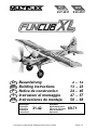 1
1
-
 2
2
-
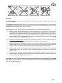 3
3
-
 4
4
-
 5
5
-
 6
6
-
 7
7
-
 8
8
-
 9
9
-
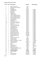 10
10
-
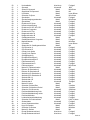 11
11
-
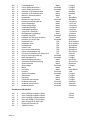 12
12
-
 13
13
-
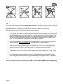 14
14
-
 15
15
-
 16
16
-
 17
17
-
 18
18
-
 19
19
-
 20
20
-
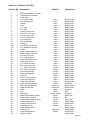 21
21
-
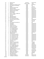 22
22
-
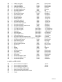 23
23
-
 24
24
-
 25
25
-
 26
26
-
 27
27
-
 28
28
-
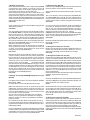 29
29
-
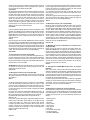 30
30
-
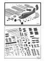 31
31
-
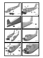 32
32
-
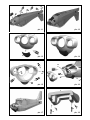 33
33
-
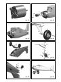 34
34
-
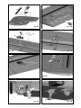 35
35
-
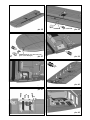 36
36
-
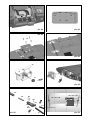 37
37
-
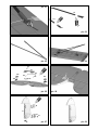 38
38
-
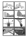 39
39
-
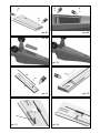 40
40
-
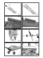 41
41
-
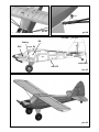 42
42
-
 43
43
-
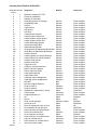 44
44
-
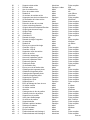 45
45
-
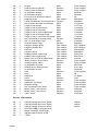 46
46
-
 47
47
-
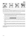 48
48
-
 49
49
-
 50
50
-
 51
51
-
 52
52
-
 53
53
-
 54
54
-
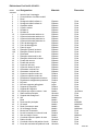 55
55
-
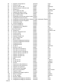 56
56
-
 57
57
-
 58
58
-
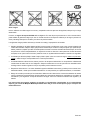 59
59
-
 60
60
-
 61
61
-
 62
62
-
 63
63
-
 64
64
-
 65
65
-
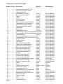 66
66
-
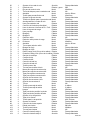 67
67
-
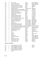 68
68
-
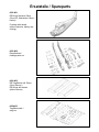 69
69
-
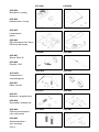 70
70
-
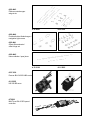 71
71
-
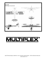 72
72


MULTIPLEX Funcub Xl Le manuel du propriétaire
- Catégorie
- Jouets télécommandés
- Taper
- Le manuel du propriétaire
- Ce manuel convient également à
dans d''autres langues
Documents connexes
-
MULTIPLEX Bk Funcub Ng Le manuel du propriétaire
-
-
MULTIPLEX 2 Heron Le manuel du propriétaire
-
-
-
MULTIPLEX Rockstar Le manuel du propriétaire
-
-
-
-

