
TM
Instruction Manual
Manuel d’instructions
1-Tap Kegerator™
Product no. 399-6488-6
Référence produit 399-6488-6

2
Product no. 399-6488-6
SAFETY TABLE OF CONTENTS
SAFETY 2
IMPORTANT SAFEGUARDS 3
ADDITIONAL IMPORTANT SAFEGUARDS 3
INTRODUCTION 5
PARTS 6
INSTALLING THE CASTORS 8
ASSEMBLY OVERVIEW 8
TAP TOWER INSTALLATION 9
ATTACHING COUPLER TO TAP TOWER 9
ATTACHING COUPLER TO REGULATOR 10
ATTACHING REGULATOR TO CO
2
TANK 10
COMPLETED CO
2
TANK INSTALLATION 11
TEMPERATURE GAUGE 12
INSTALLING THE GUARDRAIL / DRIP TRAY 12
TAPPING THE BEER KEG 13
SETTING THE REGULATOR 14
HOW TO OPERATE 16
CONVERT TO REFRIGERATOR 16
HELPFUL TIPS 17
CLEANING & MAINTENANCE 18
WARRANTY 19
SAFETY
Your safety and the safety of others is very important.
We have provided many important safety messages in this manual and on your appliance. Always read and
obey all safety messages.
This is the safety alert symbol.
This symbol alerts you to potential hazards that can cause serious injury to you and others.
All safety messages will follow the safety alert symbol.
All safety messages will tell you what the potential hazard is, tell you how to reduce the chance of injury, and
tell you what can happen if the instructions are not followed.
Appliance Specifications:
90 W, 115 V, 60 Hz
9H72
HOUSEHOLD REFRIGERATOR

3
TM
IMPORTANT SAFEGUARDS
IMPORTANT SAFEGUARDS
A person who has not read and understood all operating and safety instructions is not qualified to
operate this appliance. All users of this appliance must read and understand this Instruction Manual
before operating or cleaning this appliance.
When using electrical appliances, basic safety precautions should always be followed, including:
1. Read all instructions before operating this appliance.
2. DO NOT TOUCH the hot surfaces. Use handles or knobs.
3. This appliance is NOT A TOY.
4. Keep out of reach of children.
5. Unsupervised young children and cognitively challenged individuals should never operate this appliance.
6. Close supervision is necessary when any appliance is used by or near children.
7. To protect against electrical shock do not immerse cord, plug or any part of this unit in water or other liquids.
8. Do not operate this appliance when parts are missing or broken.
9. Unplug from outlet when not in use, before removing parts and before cleaning. Allow to cool before putting on
or taking off any parts, and before cleaning.
10. DO NOT operate any appliance with a damaged cord or plug, or after the appliance malfunctions, or if the
appliance has been damaged in any manner. Return the appliance to the nearest repair shop for examination,
repair or adjustment.
11. The manufacturer does not recommend the use of accessory attachments other than what is provided by the
manufacturer. Use of attachments may cause injuries.
12. DO NOT use the appliance for other than its intended use.
13. DO NOT use outdoors. FOR HOUSEHOLD USE ONLY.
14. DO NOT place on or near a hot gas or electric burner, or in a heated oven.
15. DO NOT put any parts of this appliance in dishwasher.
16. DO NOT let cord hang over edge of table or counter, or touch hot surfaces.
17. NEVER leave unit unattended while in use or when plugged into an outlet.
18. Always attach plug to appliance first, then plug cord in the wall outlet. To disconnect, turn any control to "off,"
then remove plug from wall outlet.
ADDITIONAL IMPORTANT SAFEGUARDS
Operating Safety Precautions
1. Before discarding your old appliance, remove the door from its hinges so that children do not easily
become trapped inside.
2. DO NOT roll this appliance with loaded beer kegs onto carpeted floor.
3. The appliance door must be closed during operation. DO NOT leave the door open when children are near.
4. This appliance should not be recessed or built into an enclosed cabinet. It is designed for freestanding
assembly only.
5. Do not operate your appliance in the presence of explosive fumes.
6. Do not tamper with the controls.
ADDITIONAL IMPORTANT SAFEGUARDS

4
Product no. 399-6488-6
ADDITIONAL IMPORTANT SAFEGUARDS
Instructions for the Electrical Cord and Plug
1. ELECTRICAL SHOCK HAZARD: Failure to follow these instructions can result in death, fire, or electrical shock.
•
Plug into a grounded 3 prong outlet.
•
DO NOT remove ground prong.
•
DO NOT use an adaptor.
•
DO NOT use an extension cord.
2. This unit MUST be grounded. In the event of an electrical short circuit, grounding reduces the risk of electric
shock by providing an escape wire for the electric current. This unit is equipped with a cord having a grounding
wire with a grounding plug.
The plug must be plugged into an outlet that is properly installed and grounded.
3. WARNING: Improper use of the grounding plug can result in a risk of electric shock. If the plug does not fit
fully into the outlet, contact a qualified electrician. Do not attempt to modify the plug in any way.
4. A short power supply cord is provided to reduce the risk of becoming entangled or tripping over a long cord.
5. The manufacturer does not recommend using this machine in countries that do not support 120 V AC even if a
voltage adaptor, transformer, or converter is in use.
CO
2
(Carbon Dioxide) Gas
1. CO
2
gas can be dangerous! CO
2
cylinders contain high-pressure compressed gas, which can be hazardous if not
handled properly. Make sure you read and understand all the procedures for the CO
2
cylinders before installation.
2. Always connect the CO
2
cylinder to a regulator! Failure to do so may cause an explosion resulting in possible
death or injury when the cylinder valve is opened,
3. Never connect the CO
2
cylinder directly to the beer keg.
4. Always follow the correct procedures when changing the CO
2
cylinder.
5. Never drop or throw a CO
2
cylinder.
6. Always keep CO
2
cylinders away from heat. Store extra cylinders in a cool place (preferably 21°C/ 70°F). Fasten
securely with a chain when storing in an upright position.
7. ALWAYS ventilate and leave the area immediately if CO
2
leakage has occurred.
8. There are two safety devices in the pressure system in the form of a valve. One safety feature is on the CO
2
bottle. The second is on the regulator.
9. Never attempt to refill CO
2
cylinder yourself.
10. IMPORTANT! If the refrigerator has been placed in a horizontal or tilted position for any period of time, wait 8
hours before plugging in the unit.
SAVE THESE INSTRUCTIONS!

5
TM
INTRODUCTION
Sixth Barrel
23 3/8"
59.4 cm
9 1/4"
23.5 cm
13 7/8"
35.5cm
16 1/8"
41 cm
23 3/8"
59.4 cm
11 1/8"
28.3 cm
23 3/8"
59.4 cm
16 1/8"
41 cm
INTRODUCTION
Great for serving even the thirstiest crowd, this appliance keeps the beer flowing and the good times rolling. This unit
adds a unique element to backyard barbecues, garage hangouts, recreation rooms, or simply relaxing at home.
Proper Location
To ensure that your appliance works to the maximum efficiency for which it was designed, keep it in a location where
there is proper air circulation and electrical outlets. Choose a location where this appliance will be away from heat and
will not be exposed to direct sunlight.
•
Indoor use only. It should not be used outdoors.
•
Designed to be freestanding and should not be placed in a built-in or recessed area.
•
Unit includes a 2.5 lb. CO
2
bottle, which should be able to dispense two to four 15 gallon kegs of beer.
•
Capacity: 4.9 cu. ft.
•
Unit dimensions: 20 x 24 ¾ x 48 ½"(51 x 63 x 123.3 cm)
•
The following dimensions are recommended for clearances around the this appliance:
Sides …………………… ¾” (19 mm)
Back ……………………. 1” (25 mm)
•
Unit weight: 87 lbs 8 oz
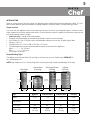
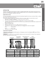
Compatible Keg Types
The appliance can hold one Barrel full-size Keg, or one Pony Keg, or two 5-Gallon Kegs. DOES NOT fit
non-standard keg sizes.
NOTE: Keg Coupler only fits D-Sankey Keg Valves. Attaching the Keg Coupler will add height to the Keg.
Quarter Barrel
(Pony Keg)
Slim Quarter Barrel
(Tall Keg)
½ Barrel
(Full Size)
Kegs Barrel ¼ Barrel Short ¼ Barrel Slim ½ Barrel
Gallons 5.23 7.75 7.75 15.50
Keg Capacity 1 1 1 1
12 oz. Beers 55 82 82 165
Weight (Full)
58 lb
26.3 kg
87 lb
39.5 kg
87 lb
39.5 kg
161 lb
73 kg

6
Product no. 399-6488-6
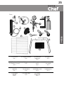
PARTS
PARTS
Read all instructions carefully before assembling this appliance.
IMPORTANT! Stand this appliance in an upright position for 8-10 hours before plugging into an electrical outlet.
This will allow the coolant in the refrigeration unit to stabilize before turning on the power.
If still unsure whether your appliance has been properly assembled, it is recommended that you contact customer
service, or a qualified installer, such as a brewery or wherever kegs are sold.
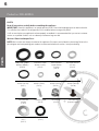
Washers / Beer Line Adaptor Parts
NOTE: Most washers are already attached to this appliance. Extra parts are included in a plastic bag. Refer to the
parts diagram and corresponding part numbers to understand where each washer / extra parts belong.
Hose Clamps
(Part 4)
Body Seal Coupler
Washer (38 mm)
(Part 5)
Probe Seal Coupler
Washer (22 mm)
(Part 5)
Tap Tower
Washer (24 mm)
(Part 1)
Spigot Handle
Washer (15 mm)
(Part 2)
Inner Probe Seal
Coupler Washer
(23 mm)
(Part 5)
Tap Tower Spigot
Washer (13 mm)
(Part 3)
Top Coupler Washer
(20 mm)
(Part 5)
Regulator High Pressure
Washer (18 mm)
(Part 6)
CO
2
Hole Plug
(Exterior Cabinet)
CO
2
Directional
Washer
(Part 5)
Metal Washer
Qty. 2
(Part 11)
Backflow Stopper
(Part 5)
Tap Tower Washer
(Part 1)

7
TM
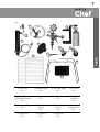
Parts
2
4
3
1
5
9
13
6
10
11
7
15
8
12
14
(1) Tap Tower
Qty. 1
(2) Spigot Handle
Qty. 1
(6) Regulator
Qty. 1
(5) Keg Coupler
(US Sankey D-System)
Qty. 1
(3) Tap Tower Spigot
Qty. 1
(7) CO
2
Tank Holder
Qty. 1
(10) Tap Tower
Wrench
Qty. 1
(9) Top Cabinet Plug
Qty. 1
(13) Wire Shelf
Qty. 2
(14) Guard Rail
Qty. 1
(4) CO
2
Line
Qty. 1
(8) CO
2
Tank
(unfilled)
Qty. 1
(11) Front Locking
Castors
Qty. 2
(15) Drip Tray
Qty. 1
(12) Rear Non-
Locking Castors
Qty. 2
PARTS

8
Product no. 399-6488-6
ASSEMBLY OVERVIEW INSTALLING THE CASTORS
Unlocked Locked
Tap Tower
CO
2
Line
Keg Coupler
CO
2
Tank
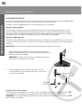
INSTALLING THE CASTORS
NOTE: Each of the Front Castors include a locking mechanism to ensure the unit does not roll on hard floors. The
Front Castors should be fastened at the front end of the unit, with the Non-Locking Rear Castors fastened on the
rear end.
1. Empty the inside of the cabinet and lay the unit down on its side. To prevent
dents or scratches, we recommend placing a piece of cardboard or cloth
underneath the cabinet.
2. For the Front Castors, place Metal Washers over the Castor bolts, then insert
the Castors into the holes on the bottom corners of the cabinet. (The Rear
Castors do not require Metal Washers.) Tighten each Castor by turning each
metal bracket clockwise.
3. Once all four Castors have been tightened, stand the cabinet in the upright
position.
Locking The Front Castors
ASSEMBLY OVERVIEW
Regulator

9
TM
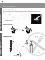
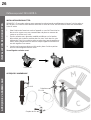
ATTACHING COUPLER TO TAP TOWER TAP TOWER INSTALLATION
1.
Remove & discard
Insert (rounded
side down)
2.
Tap Tower
3.
3.
1.
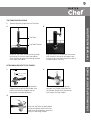
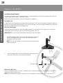
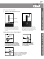
TAP TOWER INSTALLATION
Remove all packing tape from the Tap Tower.
2.
ATTACHING COUPLER TO TAP TOWER
Remove the packing spring and Backflow
Stopper from inside the Keg Coupler, then
reinsert the Backflow Stopper into the
Keg Coupler (rounded side down).
Remove the black packing cap from
the top of the Coupler, then place the
Top Coupler Washer flush and centred
on the top of the Keg Coupler.
After the Tap Tower has been placed
on top the cabinet and the hose line
feeds through the bottom, attach the
wing nut to the Keg Coupler.
Guide the Tap Tower Washer up the tap tower
hose and let it sit on the top of the cabinet.
Then feed the tap tower hose through the hole
in the top of the cabinet.
Align the notches at the bottom of the tower
with the hole in the top of the cabinet, then
insert and twist the tower clockwise to lock it
into place (about a ¼ turn).
Tap Tower Washer

10
Product no. 399-6488-6
ATTACHING REGULATOR TO CO
2
TANK
ATTACHING COUPLER TO REGULATOR
3.
2.
1.
2.
Hose
Clamp
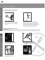
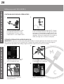
ATTACHING COUPLER TO REGULATOR
1.
ATTACHING REGULATOR TO CO
2
TANK
IMPORTANT! When you purchase your first keg of beer, you must also have your CO
2
Tank filled by a local supplier.
CO
2
Tanks can be filled at locations such as welding supply shops, party stores, and wherever kegs are purchased.
If not already inserted, insert the CO
2
Directional Washer into the Keg Coupler.
Then screw the CO
2
Line onto the Keg
Coupler.
Push the other end of the CO
2
Line through
the hole in the rear of the cabinet. Slide a Hose
Clamp onto the end of the CO
2
Line, then attach
the hose to the barb fitting on the bottom of the
regulator. Secure the CO
2
Line by tightening the
Hose Clamp with a flathead screwdriver.
Align and hook the 4 holes of the
CO
2
Tank Holder with the screws
on the back of the unit.
4.
Use an adjustable wrench
(not included) to attach the
Regulator to the CO
2
Tank.
Place the CO
2
Tank into the
CO
2
Tank Holder.
Make sure the white nylon High
Pressure Washer (already installed)
is attached to the Regulator.

11
TM
COMPLETED CO
2
TANK INSTALLATION
DANGER! CO
2
can be dangerous! CO
2
cylinders contain
high-pressured gas, which can be hazardous if handled
improperly. They must be handled with care.
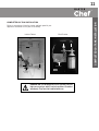
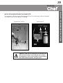
COMPLETED CO
2
TANK INSTALLATION
Below is an overview of how the interior and back panel of your
appliance should look at this point of assembly.
Tap Tower
Hose
Regulator
CO
2
Tank
CO
2
Tank
Keg
Coupler
Connects
to Keg
CO
2
Line
Interior Cabinet Back Exterior

12
Product no. 399-6488-6
INSTALLING THE GUARDRAIL / DRIP TRAY
TEMPERATURE GAUGE
Tap Tower
Assembly
Tap Tower
Handle
Drip Tray
OFF
Warmer Normal Use Colder
1 2 3 4 5 6 7
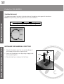
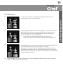
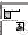
TEMPERATURE GAUGE
The temperature gauge is located in the interior cabinet of the appliance in the upper left-hand corner.
NOTE: Before purchasing a beer keg, allow the unit to cool for 48 hours.
INSTALLING THE GUARDRAIL / DRIP TRAY
1. Place the Guardrail on top of the unit and align all pegs of
the Guardrail with the holes on top of the unit.
2. Secure the Guardrail to the unit by pushing the pegs inside
the corresponding holes.
3. Place the Drip Tray at the base of the Tap Tower.
Guardrail

13
TM
TAPPING THE BEER KEG
1.
3.
2.
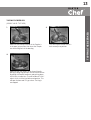
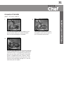
TAPPING THE BEER KEG
(SINGLE VALVE-TYPE KEG)
Make sure the black pull handle of the Coupler is
in the open (up) position, then insert the Coupler
into the locking neck of the beer keg.
Turn the Coupler clockwise until it
locks securely into position.
Make sure the Tap Tower is in the closed (handle
pointing straight up) position. Secure the connection
by pulling the Coupler handle out and pushing down
until it locks into position. The pull handle will "click"
when it shifts into the final downward position. This
will open the beer and CO
2
gas valves. The Keg is
now tapped.

14
Product no. 399-6488-6
SETTING THE REGULATOR
CO
2
Shut Off Valve:
(shown in open position)
Connects to
CO
2
Tank
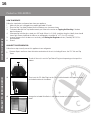
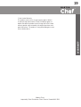
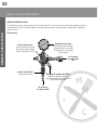
SETTING THE REGULATOR
Connects to
CO
2
Line
Overview
The Regulator connects the CO
2
Tank to the CO
2
Line, while measuring PSI (pounds per square inch) and the volume
of CO
2
in the tank. Set the Output Pressure Gauge between 8-12 PSI for a nice, frothy head.
Pressure Relief Valve
(PRV): Allows gas to
flow through Regulator
to obtain an accurate
pressure reading.
Pressure Dial: Adjusts
the output pressure
(loosen set screw with
Allen Wrench)
Output Pressure Gauge:
Measures PSI of CO
2
outflow from CO
2
Tank to Keg (0-60 PSI)

15
TM
SETTING THE REGULATOR
How To Set Regulator
1.
2.
3.
4.
Close the Shut Off Valve on the Regulator, and open the CO
2
Tank valve
completely by turning it counter-clockwise.
Slowly turn Pressure Dial all the way to the negative ( - ), then pull the Pressure
Relief Valve (PRV) to ensure an accurate reading. Then very slowly turn the
Pressure Dial clockwise until the desired pressure is shown on the Output
Pressure Gauge (8-12 PSI is recommended).
» Turning clockwise will increase the output pressure (higher PSI).
» Turning counter-clockwise will decrease the output pressure (lower PSI).
Once desired pressure is reached, tighten the inner Locking Ring. Pull the PRV to
assure the correct setting. If necessary, readjust your settings.
Next, open the CO
2
Shut Off Valve on the Regulator to allow gas to flow from
the Regulator to the Keg Coupler. You will hear the keg pressurizing. The output
needle will drop momentarily until the pressure has equalized. Then the needle will
return to the point you set it at.
Finally, we suggest you re-check the output pressure on the Regulator, and if necessary re-adjust starting at
step #1 until the desired pressure is reached.

16
Product no. 399-6488-6
CONVERT TO REFRIGERATOR HOW TO OPERATE
2.
1.
3.
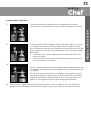
HOW TO OPERATE
Follow the steps below to dispense beer from your appliance.
1. Make sure the unit is plugged into a properly grounded AC outlet.
2. Place the Drip Tray under the beer faucet to avoid messes from excess beer.
3. To dispense beer pull the Tap Handle towards you. Refer to the section on Tapping the Beer Keg if the beer
does not dispense.
4. When pouring, hold the glass steady at a 45° angle. When it is 2/3 full, straighten the glass. Ideally, foam should
have a tight creamy head and the collar on an average glass should be ¾” to 1” (2 to 2.5 cm) high.
5. Increase the pressure if the beer runs too slowly (see Setting the Regulator section). Generally, 8-10 PSI is
recommended.
6. Cheers!
4.
To seal off the unit, insert the Top Cabinet Plug into the opening on the top of the
cabinet.
Remove all parts and hoses from the interior and exterior of the unit, including all hoses, the CO
2
Tank and Tap
Tower.
Then insert the CO
2
Hole Plug into the CO
2
Line hole located in the upper left corner
on the back exterior of the cabinet.
Arrange the included Wire Racks in the cabinet interior to fit your refrigeration
needs.
CONVERT TO REFRIGERATOR
Follow these steps to easily convert this appliance into a refrigerator.

17
TM
HELPFUL TIPS
HELPFUL TIPS
•
IMPORTANT! If the refrigerator has been placed in a horizontal or tilted position for any period of time, wait 8
hours before plugging the unit in.
•
It is recommended that you flush the hoses with water prior to first use to remove any dust and debris from
shipping.
•
Open the CO
2
Tank with a ¼ turn to start, then use the regulator to adjust to desired pour. If it is not enough,
continue to open the CO
2
Tank by a ¼ turn and use regulator until desired setting is reached.
•
It is normal to see condensation form on the faucet. It is caused by the difference in temperature between the
cold beer and the inside of the faucet when beer is flowing through the line.
•
Humidity can cause ice to build up inside the unit, so you will need to periodically defrost it. A hole in the back of
the unit will allow water to drain out of the appliance.
NOTE: Do not use sharp objects to remove ice build up as this may damage the unit.
Foamy Beer
Follow these steps to prevent foamy beer:
1. Confirm the packing spring in the Keg Coupler is removed and discarded. It is not to be placed inside the Keg
Coupler when unit is assembled.
2. Make sure there is only one Backflow Stopper inserted and it falls out easily if the Keg Coupler is flipped over.
If you have to force it out with a screwdriver, it is getting lodged in the Keg Coupler. Try exchanging it with the
included replacement.
3. Confirm the beer lines are not kinked and are clean.
4. You may need to adjust down your pressure, even if it is below the recommended 8-12 PSI:
•
Before lowering the pressure, close the CO
2
Shut Off Valve (turn to 9 o’clock position) and use a 1.5 mm
Allen Wrench to loosen the Allen Set Screw on the red +/- adjustment dial. This will restrict excess CO
2
from entering the keg.
•
Adjust the pressure down to 8 PSI or below. Lock the red +/- dial back in place by tightening with the Allen
Wrench.
•
Pull the Release Valve on the Regulator to get an accurate reading of CO
2
pressure.
•
With the Shut Off Valve still closed, move down to your Coupler.
•
Pull the release valve on the Coupler to remove any excess CO
2
that may have been pushed into the keg at
another point.
•
Once most or all has released, open the Shut Off Valve (6 o’clock position) and attempt to pour a beer.
5. Keep in mind that jostling a keg can create foamy beer.
6. Temperature also may affect the beer, so be sure it is not too warm or too cold. 3°C / 37°F is an ideal
temperature.
7. A faulty valve on the keg itself may cause the Keg Coupler to not seal well. Make sure all connections are secure
and well tightened. Ensure all Washers are intact and correctly placed. Confirm the Directional Washer has a hole
in it when pinched between the fingers.

18
Product no. 399-6488-6
CLEANING & MAINTENANCE
Tap Tower Spigot
Spigot Handle
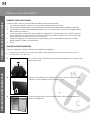
CLEANING & MAINTENANCE
To prevent the buildup of yeast, mould and bacteria, it's recommended that you clean your appliance every time you
switch a keg or every five weeks, whichever is shorter.
NEVER use an abrasive sponge, cloth or scouring pad on this appliance.
Clean Beer Lines
For best results, we recommend purchasing a beer line cleaning kit. There are several different methods for cleaning
beer lines, including hand pump cleaning kits, pressurized cleaning kits, and recirculating cleaning pumps. Follow the
directions included in each kit to clean the beer lines.
Clean Tap Tower Spigot
As beer residue left behind on the Tap Tower Spigot evaporates, it leaves behind sticky sugars that can make the
handle hard to pull. To avoid this, clean the Tap Tower Spigot after every use.
IMPORTANT! Be sure to untap your keg before removing the Tap Tower Spigot.
2. Wash the Spigot Handle, Tap Tower Spigot and interior spring in hot,
soapy water. Allow parts to dry before reassembling.
When Unit Is Not In Use
Adjust the temperature dial to "Warmer", especially when in colder environments as this unit does not self-defrost
and ice may build up inside the unit.
NOTE: To avoid permanent damage to the unit, never use sharp objects to remove built up ice inside the unit.
1. Remove the Spigot Handle, then use the Tap Tower Wrench to remove
the Tap Tower Spigot. Be sure to not lose the interior spring when
removing the Tap Tower Spigot.
NOTE: The Tap Tower Spigot has a reverse thread and can be removed
by turning clockwise.
Spring

19
TM
WARRANTY
1-Year Limited Warranty.
This product carries a one (1) year warranty against defects
in workmanship and materials. Trileaf Distribution agrees to
replace the defective product free of charge within the stated
warranty period, when returned by the original purchaser with
proof of purchase. This product is not guaranteed against wear,
misuse and/or abuse.
Made in China
Imported by Trileaf Distribution Trifeuil Toronto, Canada M4S 2B8

20
Référence produit 399-6488-6
SÉCURITÉ TABLE DES MATIÈRES
SÉCURITÉ 20
PRÉCAUTIONS IMPORTANTES 21
PRÉCAUTIONS IMPORTANTES ADDITIONNEL 21
INTRODUCTION 23
PIÈCES 24
INSTALLATION DES ROULETTES 26
APERÇU DE L'ASSEMBLAGE 26
INSTALLATION DE LA TOUR À FÛT 27
FIXATION DU COUPLEUR À LA TOUR DE ROBINET 27
FIXATION DU COUPLEUR SUR LE RÉGULATEUR 28
ATTACHER LE RÉGULATEUR AU RÉSERVOIR DE CO
2
28
INSTALLATION DU RÉSERVOIR DE CO
2
COMPLÉTÉE 29
JAUGE DE TEMPERATURE 30
INSTALLER LE GARDE-CORPS / LE PLATEAU D'ÉGOUTTAGE 30
PERÇAGE DU FÛT DE BIÈRE 31
RÉGLER LE RÉGULATEUR 32
COMMENT FAIRE FONCTIONNER 34
CONVERTIR EN RÉFRIGÉRATEUR 34
CONSEILS UTILES 35
NETTOYAGE ET ENTRETIEN 36
GARANTIE 37
SÉCURITÉ
Votre sécurité et la sécurité des autres est très importante.
Nous avons fourni de nombreux messages de sécurité importants dans ce manuel et sur votre appareil.
Toujours lire et respecter les messages de sécurité.
Ceci est le symbole d'alerte de sécurité.
Ce symbole vous signale les dangers potentiels qui peuvent causer des blessures graves pour vous
et les autres.
Tous les messages de sécurité suivront le symbole d'alerte de sécurité.
Tous les messages de sécurité vous diront quel est le danger potentiel et vous diront comment réduire le
risque de blessure et vous dire ce qui peut arriver si les instructions ne sont pas suivies.
Spécifications de l'appareil :
90 W, 115 V, 60 Hz
9H72
HOUSEHOLD REFRIGERATOR
La page est en cours de chargement...
La page est en cours de chargement...
La page est en cours de chargement...
La page est en cours de chargement...
La page est en cours de chargement...
La page est en cours de chargement...
La page est en cours de chargement...
La page est en cours de chargement...
La page est en cours de chargement...
La page est en cours de chargement...
La page est en cours de chargement...
La page est en cours de chargement...
La page est en cours de chargement...
La page est en cours de chargement...
La page est en cours de chargement...
La page est en cours de chargement...
La page est en cours de chargement...
La page est en cours de chargement...
-
 1
1
-
 2
2
-
 3
3
-
 4
4
-
 5
5
-
 6
6
-
 7
7
-
 8
8
-
 9
9
-
 10
10
-
 11
11
-
 12
12
-
 13
13
-
 14
14
-
 15
15
-
 16
16
-
 17
17
-
 18
18
-
 19
19
-
 20
20
-
 21
21
-
 22
22
-
 23
23
-
 24
24
-
 25
25
-
 26
26
-
 27
27
-
 28
28
-
 29
29
-
 30
30
-
 31
31
-
 32
32
-
 33
33
-
 34
34
-
 35
35
-
 36
36
-
 37
37
-
 38
38


Master Chef 399-6488-6 Manuel utilisateur
- Taper
- Manuel utilisateur
- Ce manuel convient également à
dans d''autres langues
- English: Master Chef 399-6488-6 User manual
Autres documents
-
Igloo BK49BS Manuel utilisateur
-
Nostalgia Electrics KRS-6100SS Mode d'emploi
-
BLACK DECKER BBD20HS Manuel utilisateur
-
Danby DKC054A1BSL2DB Manuel utilisateur
-
Haier BrewMaster HBF205E Manuel utilisateur
-
Danby DKC054A1BSLDB Manuel utilisateur
-
Kenmore 25591589010 Le manuel du propriétaire
-
-
Haier BrewMaster HBF05E Manuel utilisateur
-
Nostalgia CBD5BS Manuel utilisateur