
WARNING - FOR YOUR SAFETY - This product must be installed and serviced by
authorized personnel, qualifi ed in pool/spa heater installation. Improper installation
and/or operation can create carbon monoxide gas and fl ue gases, which can cause
serious injury, property damage, or death. For indoor installations, as an additional
measure of safety, Jandy Pool Products, Inc. strongly recommends installation of
suitable Carbon Monoxide detectors in the vicinity of this appliance and in any adja-
cent occupied spaces. Improper installation and/or operation will void the warranty.
Installation and
Operation Manual
LXi
™
Gas-Fired Pool
and Spa Heater
Model LXi
™
Natural Gas and LP
WARNING
If these instructions are not followed exactly, a fi re or explosion may result,
causing property damage, personal injury, or death.
Do not store or use gasoline or other fl ammable vapors and liquids in the
vicinity of this or any other appliance.
WHAT TO DO IF YOU SMELL GAS
• Do not try to light any appliance.
• Do not touch any electrical switch; do not use any phone in your building.
• Immediately call your gas supplier from a neighbor’s phone. Follow the gas
supplier’s instructions.
• If you cannot reach your gas supplier, call the fi re department.
Installation and service must be performed by a qualifi ed installer, service
agency or the gas supplier.
Installation and Operating Data
H0286900E


LXi
™
Pool/Spa Heater Installation and Operation Manual Page 3
Section 1. General Information .............. 5
1.1 Introduction ..............................................5
1.2 Consumer Information and Safety ...........5
1.2.1 Spa/Hot Tub Safety Rules ..........5
1.2.2 Swimming Pool Energy
Saving Tips ................................6
1.3 Warranty ..................................................6
1.4 Codes and Standards ..............................6
1.5 Technical Assistance ...............................7
1.6 Materials Installer Must Provide ..............7
1.6.1 Materials for All Applications ......7
1.6.2 Materials for Special
Applications ................................7
1.7 Specifi cations ..........................................7
1.7.1 General Specifi cations ...............7
1.7.2 Dimensions ................................8
Section 2. Installation Instructions ........ 9
2.1 Introduction ..............................................9
2.2 Field Assembly .......................................9
2.3 Location Requirements ...........................9
2.3.1 Introduction ................................9
2.3.2 Clearances .................................9
2.3.3 Flooring ......................................10
2.3.4 Outdoor Installation ....................10
2.3.5 Indoor and Outdoor Shelter
Installations ................................11
2.3.5.1 Converting the Grill to a
Vent Collar ...........................12
Section 3. Venting.................................... 12
3.1 Combustion Air Supply ............................12
3.2 Exhaust Venting ......................................13
3.3 Vent Pipe Sizing and General
Installation ..............................................14
3.3.1 Outdoor Installations ..................14
3.3.2 Indoor and Outdoor Shelter
Installations ................................14
3.3.3 Inspection and Replacement of
Existing Vent System with New
Components ..............................15
Section 4. Gas Connections ................... 16
4.1 Gas Supply and Piping ............................16
4.2 Manifold Pressure ...................................17
4.3 Special Precautions for LP Gas ..............17
Section 5. Water Connections ................ 18
5.1 Water Piping ............................................18
5.2 Check Valve Installation ..........................18
5.3 Automatic Flow Control Valve .................18
5.4 Reversible Water Connections ................18
5.5 Connections at Heater .............................20
5.6 Pressure Relief Valve ..............................22
5.7 Auxiliary Components, Chlorinators,
Ozone Generators, and Sanitizing
Chemicals ................................................23
Section 6. Electrical................................. 23
6.1 General Information .................................23
6.2 Main Power .............................................23
6.2.1 Converting the Heater for a
120V Power Source ...................25
6.3 Bonding ...................................................25
6.4 Optional Pump Connection
(Maintain Temp Feature) .........................26
6.5 Optional Remote Controls .......................26
6.5.1 Connection to a Remote
Pool-Off-Spa Selector
(3-Wire Connection) ...................27
6.5.1.1 Install the Remote Pool-Off-
Spa Selector ........................27
6.5.1.2 Confi gure the Control
Panel ...................................27
6.5.2 Connection to an AquaLink
®
RS
Control System or Remote
TSTAT (2-Wire Connection) .......27
6.5.2.1 Install the Remote TSTAT ....27
6.5.2.2 Confi gure the Control
Panel ...................................28
6.5.2.3 Remote Operation ..............28
6.5.3 Connection to a Secondary
Use Interface ..............................30
Table of Contents

Page 4 LXi
™
Pool/Spa Heater Installation and Operation Manual
Section 7. Operating Instructions .......... 30
7.1 Normal Operation ....................................30
7.2 Start-Up ...................................................30
7.3 Operating the Controller ..........................31
7.3.1 Off Mode ....................................32
7.3.2 Pool Mode - (Normal Heat) ........32
7.3.3 Pool Mode - (Optional Maintain
Heat) ..........................................32
7.3.4 Spa Mode - (Normal Heat) .........32
7.3.5 Spa Mode - (Optional Maintain
Heat) ..........................................32
7.4 User Setup Options .................................32
7.4.1 Language Setup .........................32
7.4.2 Temperature Scale Setup ..........33
7.4.3 Spa Timer Setup ........................33
7.4.4 Display Light Setup ....................33
7.5 Set Point Lockout ....................................33
7.6 Lighting and Shutdown Procedures ........33
7.6.1 Lighting the Heater .....................35
7.6.2 Shutdown ...................................35
7.7 Adjusting the Water Pressure Switch ......35
7.8 Temperature Rise ....................................36
7.9 Burner Throat Pressure Adjustment ........37
Section 8. Maintenance ........................... 37
8.1 Water Chemistry ......................................37
8.2 Seasonal Care .........................................38
8.2.1 Spring and Fall Operation ..........38
8.2.2 Winterizing .................................38
8.2.3 Spring Start-up ...........................38
8.3 Inspection and Service ............................38
8.3.1 Owner Inspection .......................39
8.3.2 Professional Inspection ..............39
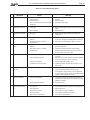
Section 9. Troubleshooting .................... 40
9.1 General Heater Troubleshooting .............40
9.2 Service Codes .........................................40
9.3 Ignition Control LED Service Codes ........40
Section 10. Professional Maintenance and
Service .................................. 43
10.1 General Information .................................43
10.2 “Premix” Forced-Draft Combustion
System ....................................................43
10.3 Heater Components and Their
Operation .................................................43
10.4 Special Service Issues - Premix
Combustion System ................................44
10.4.1 System Operation .......................44
10.4.2 Field Service and Adjustment .....44
10.4.3 Burner Throat Pressure
Adjustment .................................45
10.5 Electrical Troubleshooting .......................45
10.5.1 Electrical Power Supply ..............45
10.5.2 Controller ...................................46
10.5.3 Control Circuit Troubleshooting ..46
10.5.3.1 Transformer .........................46
10.5.3.2 Fuse ....................................46
10.5.3.3 Water Pressure Switch ........46
10.5.3.4 Fusible Link .........................47
10.5.3.5 Temperature Limit Switches
Circuit ..................................47
10.5.3.6 Blower Pressure Switch
Circuit ..................................47
10.5.3.7 Gas Valve Voltage ...............48
10.5.3.8 Igniter/Ignition Control
Circuit ..................................48
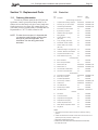
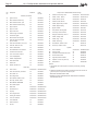
Section 11. Replacement Parts .............. 51
11.1 Ordering Information ...............................51
11.2 Parts List .................................................51
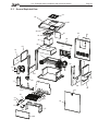
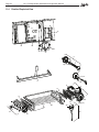
11.3 General Exploded View ...........................53
11.4 Detailed Exploded View ..........................54
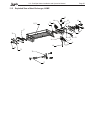
11.5 Exploded View of Heat Exchanger,
ASME ......................................................55
Table of Contents (Continued)

LXi
™
Pool/Spa Heater Installation and Operation Manual Page 5
Section 1. General Information
1.1 Introduction
This manual provides installation and operation
instructions for the LXi
™
pool and spa heaters. Read
these installation and operation instructions completely
before proceeding with the installation. Consult the
Jandy
®
factory, or local factory representative, with
any questions regarding this equipment.
Certain sections of this manual are specifi c to
either United States or Canadian installations, and are
labeled as such.
The LXi heater gets electrical power from an
external 120VAC or 240VAC source and provides a
dual electronic thermostat control system for pool/spa
combinations or preheat convenience.
The LXi heater is specifi cally designed for heat-
ing fresh water swimming pools and spas, and with
proper installation and care, they will provide years of
reliable service. Do not use the heater to maintain pool
or spa water temperature below 70°F. Do not use it as
a heating boiler or general service water heater or to
heat salt water. Consult your dealer for the appropriate
Jandy products for these applications.
In the LXi heater, operation is achieved through
use of a special “premix” combustion system. The
operation of this type of system is affected by fuel gas
properties. As noted in the troubleshooting and main-
tenance sections of this manual, adjustments may be
necessary if the local gas supply is of especially high
or low heat content.
1.2 Consumer Information and Safety
The LXi heater is designed and manufactured to
provide many years of safe and reliable service when
installed, operated, and maintained according to the
information in this manual and the installation codes
referred to in later sections. Throughout the manual
safety warnings are identifi ed by the “
” symbol and
safety cautions are surrounded by a border. Be sure to
read and comply with all of the warnings and cautions.
1.2.1 Spa/Hot Tub Safety Rules
WARNING
The following “Safety Rules for Hot Tubs,” recom-
mended by the U.S. Consumer Product Safety
Commission, should be observed when using
the spa.
AVERTISSEMENT
Les Règlements suivants pour Cuves Thermales,
tel que recommandés par la Commission U.S. de
Sécurité des Produits pour les Consommateurs,
devraient être respectés lors de l’utilisation du spa.
WARNING
The U.S. Consumer Product Safety Commission
warns that elevated water temperature can be haz-
ardous. Consult heater operation and installation
instructions for water temperature guidelines before
setting temperature.
AVERTISSEMENT
La U.S. Consumer Product Safety Commission
indique que des températures de l'eau élevées peu-
vent être dangereuses. Voir la notice d'installation et
de fonctionnement pour le réglage de la
température.
1. Spa or hot tub water temperature should never
exceed 104°F (40°C). One hundred degrees
Fahrenheit (100°F [38°C]) is considered safe for
a healthy adult. Special caution is recommended
for young children.
2. The drinking of alcoholic beverages before or
during spa or hot tub use can cause drowsiness
which could lead to unconsciousness, and subse-
quently result in drowning.
3. Pregnant women take note! Soaking in water
above 102°F (38.5°C) can cause fetal damage
during the fi rst three months of pregnancy (which
could result in the birth of a brain-damaged or
deformed child). If pregnant women are going to
use a spa or hot tub, they should make sure the
water temperature is below 100°F (38°C)
maximum.
4. The water temperature should always be checked
with an accurate thermometer before entering a
spa or hot tub. Temperature controls may vary by
as much as 1F° (1C°).
5. Persons with a medical history of heart disease,
diabetes, circulatory or blood pressure problems
should consult their physician before using a hot
tub or spa.
6. Persons taking any medication which induces
drowsiness (e.g., tranquilizers, antihistamines, or
anticoagulants) should not use spas or hot tubs.
7. Prolonged immersion in hot water can induce
hyperthermia.

Page 6 LXi
™
Pool/Spa Heater Installation and Operation Manual
Hyperthermia occurs when the internal body
temperature reaches a level several degrees above the
normal body temperature of 98.6°F (37°C). Symptoms
include dizziness, fainting, drowsiness, lethargy, and
an increase in the internal body temperature. The ef-
fects of hyperthermia include:
• Lack of awareness of impending hazard
• Failure to perceive heat
• Failure to recognize need to leave spa
• Physical inability to leave spa
• Fetal damage in pregnant women
• Unconsciousness resulting in a danger of
drowning
1.2.2 Swimming Pool Energy Saving
Tips
Jandy Pool Products, Inc., offers the following
recommendations to help conserve fuel and minimize
the cost of operating your pool heater without sacri-
fi cing comfort.
1. The American Red Cross recommends a maxi-
mum water temperature of 78°F (25°C). Use an
accurate pool thermometer. A difference of 4F°
(2°C), between 78°F and 82°F (26°C and 28°C),
will use as much as 40% more gas.
2. Carefully monitor the water temperature of your
pool in the summertime. You can reduce heater
usage due to warmer air temperatures.
3. Find the proper setting on the pool heater tem-
perature control and use the Set Point Lockout
feature to discourage further adjustments.
4. Set the pump time clock to start the pump no ear-
lier than 6:00 AM during the pool heating season.
This is the time when nightly heat loss balances.
5. If the pool is only going to be used on weekends,
reduce the heater temperature control setting by
8 or 10 degrees during the week. Reset it to the
78°F (25°C) level a day or so before you plan to
use the pool.
6. During the winter or when on vacation for longer
than a week, shut down the heater by following
the shutdown instructions found on the inside of
the heater.
7. Where possible, shelter the pool from prevailing
winds with well-trimmed hedges or other land-
scaping, cabanas, or fencing.
8. Always use a pool cover when practical. Besides
providing a valuable safety feature, a pool cover
will reduce heat loss, conserve chemicals, and
reduce the load on fi lter systems.
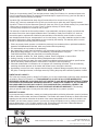
1.3 Warranty
The LXi heater is sold with a limited factory war-
ranty. Details are specifi ed on the back cover of this
manual.
Make all warranty claims to an authorized Jandy
representative or directly to the factory. Claims must
include the heater serial number and model (this infor-
mation can be found on the rating plate), installation
date, and name of the installer. Shipping costs are not
included in the warranty coverage.
The warranty does NOT cover damage caused
by improper assembly, installation, operation or fi eld
modifi cation. Also, damage to the heat exchanger by
corrosive water is NOT covered by the warranty. See
Section 8.1, Water Chemistry, for maintaining proper
pool water chemistry.
NOTE Keep this manual in a safe place for future
reference when inspecting or servicing the heater.
1.4 Codes and Standards
The LXi pool and spa heaters are design-certifi ed
by CSA (Canadian Standards Association) as com-
plying with the latest edition of the Standard for Gas
Fired Pool Heaters, ANSI Z21.56 in the USA and
CAN-4.7 in Canada.
All Jandy heaters must be installed in accordance
with the local building and installation codes as per
the utility or authorities having jurisdiction. All local
codes take precedence over national codes.
In the absence of local codes, refer to the latest
edition of the following national codes for installation:
1. In the United States, the National Fuel Gas Code,
NFPA 54/ANSI Z223.1. Pay particular attention
to the chapter addressing Venting of Equipment.
2. In Canada, the Natural Gas and Propane Instal-
lation Code, CAN/CSA-B149.1.
The LXi pool and spa heaters meet or exceed the
requirements of energy conservation regulations, such
as those in California, Hawaii, New York, Oregon and
other states that require that a pool heater have inter-
mittent ignition. In addition, the natural gas models
of this heater comply with both the California South
Coast Air Quality Management District's (SCAQMD)
Rule 1146.2 and the Title 30, Texas Administrative
Code, Chapter 117, Section 117.465 for Nitrogen
Oxide (NOx) emissions.

LXi
™
Pool/Spa Heater Installation and Operation Manual Page 7
Any changes to the heater, gas controls, gas
orifi ces, wiring, draft diverter, or improper installation
may void the warranty. If change is required to any of
the above, consult the factory.
1.5 Technical Assistance
Consult Jandy Pool Products, Inc. or your lo-
cal Jandy distributor with any questions or problems
involving the specifi cations, installation, and operation
of your Jandy equipment. An experienced member
of the technical support staff is ready to assist you in
assuring the proper performance and application of
Jandy products. For technical support, call the Techni-
cal Service Department at 1.707.776-8200,
extension 260.
1.6 Materials Installer Must Provide
1.6.1 Materials for All Applications
The following items are needed and are to be
supplied by the installer for all LXi heater
installations:
1. The correct size gas pipe to supply gas from the
meter to the heater. See Section 4.1.
2. A manually operated gas valve to be installed in
the gas line outside of the heater jacket.
3. A suitable gas union joint to connect the heater to
the gas line outside of the heater.
4. Plumbing items needed to provide a sediment
trap (drip leg) in the gas line between the manual
gas valve and the heater. See Section 4.1.
5. A 120V AC or 240V AC power supply. A junc-
tion box is not needed at the heater; connections
are made inside of the heater jacket.
1.6.2 Materials for Special
Applications
In addition to the items listed above, the follow-
ing items are needed for special applications:
1. A factory authorized vent collar and any vent
pipe needed for indoor installations in the USA
and outdoor shelter installations in Canada. (See
Section 3.3.2). A vertical vent collar comes with
the unit. A side vent kit is available from your
Jandy distributor.
2. Primer and cement suitable for cementing CPVC
pipe to PVC pipe and an appropriate coupling
for connecting the factory supplied CPVC pipe
nipples to PVC pool plumbing.
3. A noncombustible platform for installation on
combustible surfaces. (See Section 2.3.3.) Non-
combustible bases are available from your Jandy
distributor.
1.7 Specifi cations
1.7.1 General Specifi cations
1. Installation Location:
Certifi ed for use:
In the USA:
Natural Gas: Indoor and Outdoor
LP: Indoor and Outdoor
In Canada:
Natural Gas : Outdoor and Outdoor
Shelter
LP: Outdoor and Outdoor
Shelter
2. Minimum Clearance From Combustible
Material:
See Table 2 in Section 2.3.2.
3. *Gas Pipe/Heater Gas Valve Connection:
Natural Gas: 3/4" NPT
LP: 3/4" NPT
*
For diameter of gas line from meter to heater, see Table 5 in
Section 4.1.
4. Supply Gas Type:
Certifi ed for use with:
Natural Gas and LP
5. Inlet Gas Supply Pressure:
Minimum Maximum
Natural Gas: 5.0 "WC 10.5 "WC
LP: 11.0 "WC 14.0 "WC
6. Air Plenum Pressure: 1.5 "WC
7. Burner Throat Pressure: 1.0 "WC
8. Water Pipe/Heater Connection:
*2" Unthreaded PVC or CPVC
*
Other size pipes may be used. See Section 5.5 for details
9. Water Flow Rate:
Maximum: 125 gpm (475 lpm)
Minimum: 30 gpm (110 lpm)
10. Working Water Pressure:
Maximum: 75 psi
11. Exhaust Vent Connection Size:
Model:
250 6" Diameter
300 7" Diameter
400 8" Diameter

Page 8 LXi
™
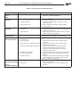
Pool/Spa Heater Installation and Operation Manual
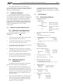
Model
Heater Width
Dim "A"
Vent Diameter Firing Rate
in. cm in. cm BTU/HR kcal
250 23.5 59.7 6 15.2 250,000 63
300 26.5 67.3 7 17.8 300,000 75
400 32.0 81.3 8 20.3 399,000 101
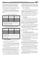
12. Electrical Supply:
Either 120 Volts AC or 240 Volts AC.
13. Modifi cation of Heater for High Altitude:
LXi heaters are normally shipped from the fac-
tory in the low altitude (sea level) operational
confi guration. Table 1 defi nes the altitude des-
ignations as described by the Standard for Gas
Fired Pool Heaters, ANSI Z21.56 in the United
States and Gas-Fired Appliances For Use At
High Altitudes, CAN1-2.17 in Canada. When
an LXi heater is to be installed in a high altitude
application, the burner throat pressure will need
to be adjusted to achieve 1.0"WC. See Section
10.4.3 for instructions on how to do this.
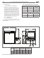
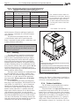
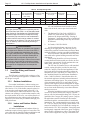
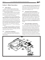
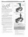
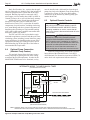
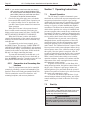
1.7.2 Dimensions
See Figure 1 for a diagram showing the heater's
exterior dimensions and dimensions to critical connec-
tions on the heater.
Figure 1. General Confi guration
A
6.9”
(17.5 cm)
11.2”
(28.4 cm)
13.1”
(33.3 cm)
27.5”
(69.9 cm)
18.5”
(47 cm)
15.5”
(
39.4 cm
)
22.3”
(56.6 cm)
5.5”
(14 cm)
6.0”
(15.2 cm)
Table 1. Altitude Designations For The LXi Heater
NATURAL GAS
ALTITUDE
DESIGNATION
UNITED
STATES
CANADA
LOW ALTITUDE 0-4500 FT 0-4500 FT
(0-1370 M)
HIGH ALTITUDE 4501-10,000 FT NOT
APPLICABLE
LP
LOW ALTITUDE 0-4500 FT 0-4500 FT
(0-1370 M)
HIGH ALTITUDE 4501-10,000 FT NOT
APPLICABLE

LXi
™
Pool/Spa Heater Installation and Operation Manual Page 9
Section 2. Installation Instructions
2.1 Introduction
WARNING
Improper installation or maintenance can cause
nausea or asphyxiation from carbon monoxide in
fl ue gases which could result in severe injury, or
death. For indoor installations, as an additional
measure of safety, Jandy Pool Products, Inc.
strongly recommends installation of suitable Car-
bon Monoxide detectors in the vicinity of this appli-
ance and in any adjacent occupied spaces.
AVERTISSEMENT
Une installation ou un entretien inadéquat peut
causer la nausée ou l’asphyxie en raison du
monoxyde de carbone présent dans les gaz de
combustion et même entraîner des blessures
graves ou la mort. Pour les installations intéri-
eures, comme mesure de sécurité additionnelle,
Jandy Pool Products, Inc. recommande forte-
ment l’installation de détecteurs de monoxyde de
carbone près de cet appareil ainsi que dans les
espaces adjacents occupés.
Install the LXi heater and vent collar in accor-
dance with the procedures in this manual, local codes
and ordinances, and in accordance with the latest edi-
tion of the appropriate national code. See Section 1.4,
Codes and Standards.
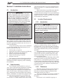
All gas-fi red products require correct installation
to assure safe operation. The requirements for pool
heaters include the following:
1. Field assembly (if required)
2. Appropriate site location (clearances) and fl ooring
3. Suffi cient combustion and ventilation air
4. Properly sized gas meter and piping
5. Proper electrical wiring (if required)
6. Adequate water fl ow
This manual provides the information needed to
meet these requirements. Review all application and
installation procedures completely before continuing
the installation.
2.2 Field Assembly
The LXi heater can be installed in a variety of
ways, some of them requiring preparation or assembly
in the fi eld. The heater is shipped from the factory
with an exhaust vent confi gured for an outdoor instal-
lation. The LXi heater is also design certifi ed for “In-
door” installations in the United States and “Outdoor
Shelter” installations in Canada when equipped with a
vent collar and the appropriately sized exhaust vent.
Check the rating plate on the heater or the Parts
List (Section 11.2) in this manual for the correct Jandy
vent collar part number. For specifi c installation infor-
mation see Section 2.3.5, Indoor and Outdoor Shelter
Installations.
Water connections are provided on the right side
of the heater but can be changed to the left side by
reversal of the heat exchanger. It is best to handle these
preparations before the heater is installed in its fi nal lo-
cation. See Section 5.4, Reversible Water Connections,
in this manual for instructions.
2.3 Location Requirements
2.3.1 Introduction
CAUTION
When pool equipment is located below the pool sur-
face, a leak from any component can cause large
scale water loss or fl ooding. Jandy Pool Products,
Inc., cannot be responsible for such water loss or
fl ooding or resulting damage.
ATTENTION
Lorsque l’équipement d’une piscine est situé sous
la surface de l’eau, une fuite provenant de n’importe
quel élément peut causer une perte d’eau importante
ou une inondation. Jandy Pool Products, Inc. n’est
pas responsable des pertes d’eau, des inondations
ou des avaries causées par une installation ou un
entretien inadéquat.
The LXi heater may be installed indoors or
outdoors, as outlined in later sections. Location of
the heater below or above the pool water level affects
operation of its water pressure switch. See sections on
water piping and heater start-up for more information
about this.
Avoid placing the heater in locations where it can
cause damage by water or condensate leakage. If this
is not possible, provide a suitable drain pan to catch
and divert any leakage. The pan must not restrict the
air fl ow around the heater.
All criteria given in the following sections refl ect
minimum clearances as stated in the national stan-
dards. However, each installation must also be evaluat-
ed, taking into account the prevailing local conditions
such as wind speed and direction, proximity and height
of walls that may block ventilation, and proximity to
public access areas.
2.3.2 Clearances
The heater must be placed to provide clearances
on all sides for maintenance and inspection. There
must also be minimum distances maintained from
combustible surfaces. See Table 2.
At least 18" (457mm) access must be available in
front of the heater for burner removal and access to
the igniter.
If the heater is to be installed in a garage, or

Page 10 LXi
™
Pool/Spa Heater Installation and Operation Manual
similar structure, all burners and burner ignition de-
vices must have a minimum 18" (457mm) clearance
above the fl oor.
This heater must be installed at least 5 feet
(1.52m) from the inside wall of a pool unless the
heater is separated from the pool by a solid fence, wall
or other permanent solid barrier.
Ce chauffe-piscine doit être installé au moins 5
pieds (1.52m) de la paroi interne de la piscine à moins
d'être isolé de la piscine par une clôture, un mur ou
autre barrière permanente.
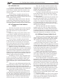
2.3.3 Flooring
The heater must be installed on a level surface
of noncombustible construction or on fi re-resistant
slabs or arches. Noncombustible fl ooring is defi ned
as fl ooring material and surface fi nish not capable of
being ignited and burning and with no combustible
materials against the underside. Acceptable materials
are those consisting entirely of a combination of steel,
iron, brick, tile, concrete, slate, glass or plaster. Do not
install the heater directly on a combustible wood or
carpet fl oor without placing a noncombustible platform
between the fl oor and the heater.
The heater can be installed on a combustible fl oor
if a noncombustible base assembly, available from
Jandy, is used. See the heater rating plate or the Parts
List (Section 11) in this manual for the appropriate
base part number. Heaters must never be installed
directly on carpeting.
As an alternative to the Jandy noncombustible
base plate, in the United States, the National Fuel Gas
Code (NFPA 54 / ANSI Z223.1), and in Canada, the
Natural Gas and Propane Installation Code (CAN/
CSA-B149.1), allow a heater to be placed on a com-
bustible surface when there is a platform under the
heater made of hollow masonry no less than 4 inches
(102 millimeters [mm]) thick, covered with sheet
metal at least 24 gauge thick and extending beyond the
full width and depth of the heater by at least 6 inches
(153 mm) in all directions. The masonry must be laid
with ends unsealed, and joints matched to provide free
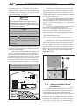
circulation of air from side to side through the
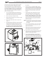
masonry. (See Figure 2.) If the heater is installed in a
carpeted alcove, the entire fl oor of the alcove must be
covered by a noncombustible panel.
2.3.4 Outdoor Installation
The LXi heater can be installed in the outdoor
confi guration as received from the factory.
Locate the heater in an open, unroofed area. Do
not install the heater under a deck. Do not locate the
heater below or adjacent to any doors, glass openings,
louvers, grills, etc., which connect in any way with an
inhabited area of a building, even though the access
might be through another structure (e.g., a garage or
utility room). In the United States the vent system
shall terminate at least 4 ft (1.2 m) below, 4 ft (1.2 m)
Table 2. Minimum Heater Clearances From Combustible Surfaces
Table 2. Dégagements Minimaux à Assurer Entre les Parois de
L'appareil et les Constructions Combustibles
Note: Clearances listed in Table 2 are
manufacturer's tested values. These are
given as minimum values. Where local
and national codes apply, and values
are different than those listed in Table
2, use the greater value to ensure safe
operation.
* In Canada - 24 in (61cm)
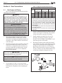
Figure 2. Noncombustible Platform
Notes:
1. Blocks must provide a solid base and be braced so they
cannot slip out of place.
2. Air openings in blocks must be arranged to provide unre-
stricted opening through entire width or length of base.
3. Sheet metal must be at least 24 ga. and extend 6" beyond
the heater jacket on all sides.
SIDE OF
HEATER
INDOOR (OUTDOOR
SHELTER) INSTALLATION
OUTDOOR INSTALLTION
INCHES CENTIMETERS INCHES CENTIMETERS
BLANK 4 10.2 4 10.2
REAR 4 10.2 4 10.2
PIPING 16 40.6 16 40.6
TOP 36 99.0 OPEN UNROOFED AREA
FRONT 18* 45.7* 18* 45.7*

LXi
™
Pool/Spa Heater Installation and Operation Manual Page 11
horizontally from, or 1 ft (300 mm) above any door,
operable window, or gravity inlet into any building. In
Canada, the heater must be installed so that the exhaust
point of the heater is at least ten (10) feet (3.0 m) from
any building opening. See Figure 3.
WARNING
United States
Do not install the heater with the top of the vent
assembly within 4 feet (1.22 m) horizontally, 4 feet
(1.22 m) below or less than 1 ft (300 mm) above of
any opening into a building.
Canada
Do not install the heater with the top of the vent as-
sembly within 10 feet (3.05 m) of any opening into a
building.
AVERTISSEMENT
Lorsque vous installez l’appareil de chauffage, as-
surez-vous que l’ouverture d’aération se trouve à un
minimum de 10 pieds (3.05 m) de toute ouverture
d’un bâtiment.
The top surface of the heater must be at least 3
feet above any forced air inlet, or intake ducts located
within 10 feet horizontally.
If the heater is installed under an overhang, there
must be a minimum clearance of 5 feet (1.5 m) above
the top of the heater and the structure should not over-
hang the heater more than 12 inches (0.30 m). The area
under the overhang must be open on three sides. This
prevents combustion gases from being diverted into
living areas through doors, windows, or gravity inlets.
Ne pas installer ce chauffe-piscine sous une
saillie mesurant moins de 3 pi de hauteur. La partie
sous la saillie doit être ouverte sur 3 côtés.
Figure 3. Outdoor Heater Installation
If the heater is installed close to a structure, pro-
tect it from rain water runoff with rain gutters on the
roof or other measures. Do not locate the heater near
irrigation sprinkler systems that could spray water on
it. Water from sprinklers may cause damage to controls
and electronic components.
Avoid locations where wind defl ection off nearby
structures might cause downdraft conditions. Where
downdraft conditions exist, locate the heater at least 3
feet (0.91 m) from vertical surfaces (e.g., nearby build-
ings and walls).
In Florida, it is required that the heater be secure-
ly fastened to the equipment pad. Use a size
1/4" x 1-1/2" long stainless steel Tapcon
®
type con-
crete screws and washers at each of the four tabs
located at the base of the heater. Mounting the appli-
ance in this manner meets the applicable requirements
of the Florida Building Code.
Tapcon
®
is a registered trademark of Illinois Tool Works (ITW), Inc.
Mounting screws are not provided with this heat-
er. After placing the heater on the equipment pad, drill
a hole in the concrete at each of the four tabs on the
feet of the heater. (The correct size drill bit is usually
provided with the concrete screws when purchased).
Place a screw in each of the holes and fasten the heater
to the equipment pad. (See Figure 4). Do not over-
torque the screws.
Figure 4. Anchor Heater To Equipment Pad
2.3.5 Indoor and Outdoor Shelter
Installations
An outdoor shelter (Canada only) is an unoccu-
pied enclosure which does not communicate directly
with occupied areas. All indoor installations and
outdoor shelter installations require a factory approved
vent collar. The vent collar must be installed without
modifi cation and in accordance with the instructions
provided by the manufacturer. For sidewall venting, a
side vent kit is available from your Jandy distributor.

Page 12 LXi
™
Pool/Spa Heater Installation and Operation Manual
Une remise extérieure (au Canada seule-
ment) est un endroit inoccupé qui ne communique
pas directement avec les endroits occupés. Toutes
les installations intérieures et remises extérieures
exigent l’addition d’une cheminée approuvée par le
manufacturier. La cheminée doit être installée sans
aucune modifi cation et selon les exigences fournies
par le manufacturier.
The applicable codes, standards and Jandy Pool
Products, Inc., require that the heater be properly
vented as outlined in this manual. Proper ventilation
of exhaust and combustion air are essential for the safe
and effi cient operation of the heater. See Section 3.
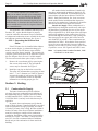
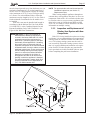
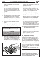
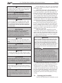
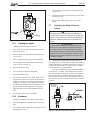
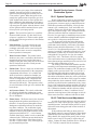
2.3.5.1 Converting the Grill to a Vent
Collar
If the LXi heater is to be installed either indoors
or in an outdoor shelter, its exhaust discharge grill
must be removed. The LXi heater comes with the
vertical vent collar factory installed. The optional side
vent plate, gasket and screws can be ordered as a parts
kit. (See the parts list in Section 11 of this manual).
The conversion can be done quite simply as follows:
1. Remove the vent exhaust grill by removing the
four screws which retain it. The grill and the
screws may be discarded. See Figure 5.
2. Install the vent pipe on the indoor vent collar.
The collar will accommodate vent piping of nom-
inal 6”, 7” or 8” diameter (see Table 4), depend-
ing upon the model of your heater. (See Figure
6.) See vent installation section for important
information on selecting proper pipe size.
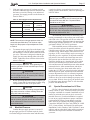
Section 3. Venting
3.1 Combustion Air Supply
The heater location must provide suffi cient
air supply for proper combustion and ventilation of
the surrounding area as outlined in the latest edition
of ANSI standard Z223.1 (NFPA 54) or in Canada,
CAN/CSA-B149.1, and any local codes that may be
applicable.
In general, these requirements specify that the
room in which a heater is installed should be provided
with two permanent air supply openings; one within
12 inches (305 mm) of the ceiling, the other within 12
inches (305 mm) of the fl oor. All indoor installations
must have openings to outside air for combustion,
ventilation, and dilution of fl ue gases from inside the
building. See Figure 7 and Table 3. Jandy Pool Prod-
ucts, Inc., does not recommend indoor installations
that do not provide combustion air from outside the
building.
All outdoor shelter installations (Canada only)
must have uninterrupted openings to outside air for
combustion and ventilation. The installation must be
in accordance with the latest edition of CAN/CSA
B149.1. Jandy Pool Products, Inc., does not recom-
mend outdoor shelter installations that depend on
internal air for combustion. Combustion air should be
ducted to the heater from outside the structure.
Outside Air Supply: When combustion air is
supplied directly through an outside wall, each open-
ing should have a minimum free area of one square
inch per 4,000 BTU/h (1.2kW) input of the total input
rating of all appliances in the enclosed area. If air is
provided through horizontal ducts, each opening and
duct must provide one square inch of fl ow area for
each 2000 BTU/h (0.6 kW). These requirements are
summarized in Table 3. Note that the areas specifi ed
are net free areas and should be increased when the
openings are covered by screens, louvers, grills or oth-
er protective covers. See Figure 8 and Table 3 notes.
Note In Canada, follow Canadian Standard, CAN/
CSA-B149.1 or local codes.
Figure 6. Vent Pipe Installation
Figure 5. Removal of Outdoor Exhaust Grill
OUTDOOR
VENT GRILL
VERTICAL
VENT
COLLAR

LXi
™
Pool/Spa Heater Installation and Operation Manual Page 13
WARNING
Do not store any chemicals, cleaners, or other cor-
rosive material near combustion air openings or in
the room. Avoid locating appliance vents in the vi-
cinity of combustion air openings. Failure to prevent
corrosive materials from mixing with combustion air
can result in reduced heater life and unsafe heater
operation.
AVERTISSEMENT
Ne pas entreposer ni utiliser d'essence ni d'autres
vapeurs ou liquides infl ammables à proximité de cet
appareil ou de tout autre appareil.
3.2 Exhaust Venting
When converted to indoor and outdoor shelter
venting confi guration, the LXi heater has a vent collar
fi tting for attachment to the venting. The diameter of
the vent collar and, thus, the minimum diameter of
the vent pipe to be used is determined by the model
of heater installed and the type of venting. The only
correct procedure for vent pipe sizing is to do so in
accordance with Table 4 and the applicable installa-
tion code as stated in the following "Danger" warn-
ing. Note that with horizontal Category III type vent
installations, the venting may be smaller than the vent
collar for Category I vertical venting. See Table 4.
Table 3. Air Openings to Outside
Exhaust Fans or Vents: Any equipment
which exhausts air from the room where the heater
is installed can deplete the combustion air supply or
reverse the natural draft action of the venting system.
This could cause fl ue products to accumulate in the
room. Additional air must be supplied to compensate
for such exhaust.
The information in Table 3 is not applicable in
installations where exhaust fans or blowers of any type
are used. Such installations must be designed by quali-
fi ed engineers.
The heater must be completely isolated and
protected from any source of corrosive chemical fumes
such as those emitted by trichlorethylene, perchloro-
ethylene, chlorine, etc.
3)
Notes:
1. Use approved
roof jack.
Figure 7. Indoor Installation Venting (USA), or Outdoor Shelter (Canada)
Required Net Free Open Area*
for Combustion Air Openings
*Area indicated is for one of two openings; one at fl oor level and
one at the ceiling, so the total net free area would be double the
fi gures indicated. For special conditions, refer to NFPA54 ANSI
Z223.1. In Canada refer to the National Standard CAN/CSA-
B149.1 which differs from this table.
Note: If using screens and/or metal louvers, compensate by adding
50% additional area to each opening. If using wood louvers each open-
ing must be at least four times the area indicated in the table above.
Model
Direct from outside Duct from outside
in
2
(cm
2
)in
2
(cm
2
)
250 63 (406) 126 (813)
300 75 (484) 150 (968)
400 100 (645) 200 (1290)

Page 14 LXi
™
Pool/Spa Heater Installation and Operation Manual
WARNING
Vent pipe diameter must be as required by the Na-
tional fuel Gas Code Z223.1 or the Canadian Instal-
lation Codes for Gas Appliances CAN/CSA-B149.1.
Undersized pipe can result in inadequate venting
and oversize pipe can result in vent condensation.
In either case the result can be release of combus-
tion products to the indoors. This can cause serious
injury or death by carbon monoxide poisoning or
asphyxiation.
AVERTISSEMENT
Le diamètre des tuyaux de ventilation doit répondre
aux exigences du National Fuel Gas Code Z223.1
ou du code canadien des installations des appar-
eils à gaz CAN/CSA B149.1. Des tuyaux trop petits
risquent d’entraîner une ventilation inadéquate et
des tuyaux trop gros risquent de provoquer une
condensation dans les tuyaux. Dans un cas comme
dans l’autre, des produits de combustion risquent
de s’échapper dans le bâtiment et causer des bles-
sures graves ou l’asphyxie par le monoxyde de
carbone.
3.3 Vent Pipe Sizing and General
Installation
The LXi may be installed with venting as a Cat-
egory I or III Fan-Assisted appliance or outdoors with
the integral vent grill.
3.3.1 Outdoor Installations
For outdoor installations, exhaust venting con-
siderations will determine the placement of the heater
(See Section 2.3.4). If the heater cannot be placed so
as to meet the requirements stated in Section 2.3.4,
a vent collar may be added to the heater to move the
exhaust vent opening to a position that complies with
the requirements. In all cases, vent collars must be of
the same diameter as the exhaust outlet of the heater.
Approved vent collars may be obtained through your
Jandy distributor.
3.3.2 Indoor and Outdoor Shelter
Installations
All indoor installations and outdoor shelter in-
stallations require a factory approved vent collar. The
vent collar must be installed without modifi cation and
the vertical vent collar comes factory installed.
All vent installations must be made in accor-
dance with all local, state or provincial codes and
with:
1. The National Fuel Gas Code, ANSI Z223.1
(NFPA 54), latest edition; pay particular at-
tention to the chapter addressing “Venting of
Equipment.” Applicable provisions of additional
applicable local building codes may also need to
be followed.
2. In Canada, CAN/CSA B149.1.
Avoid terminating heater vents near air con-
ditioning or air supply fans. The fans can pick up
exhaust fl ue products from the heater and return them
inside the building, creating a possible health hazard.
Do not locate the vent terminal where fl ue prod-
ucts could strike against building materials and cause
degradation.
Vent opening should be well away from trees
or other obstructions that would prevent free air fl ow
to and from vent terminal. Do not terminate the vent
under decks, stairways, or car ports.
The LXi may be installed for use with standard
vertical venting per tables provided in most local
codes for Category I Fan-Assisted appliances. If the
local code does not include such tables, refer to the
National Fuel Gas Code NFPA 54 / ANSI Z223.1 or
the Canadian Natural Gas and Propane Installation
Code, CAN/CSA-B149.1. Note that the tables for
fan-assisted appliances include both maximum and
minimum vent loading fi gures. The primary purpose
of the maximum ratings are to assure that the vent
operates with negative pressure throughout its length.
The minimum ratings are to assure that vent gases do
not cool too much and thereby assure that condensa-
tion does not occur.
When the installation requires horizontal venting
in excess of what is allowed for Category I installa-
tions or calls for horizontal discharge, the LXi may be
installed with a Category III venting system. Category
III applications must be installed per this installa-
tion manual and the vent manufacturer's installation
instructions. The venting materials must comply with
UL 1738 for Category III venting systems and be con-
structed of stainless steel. In Canada, the venting ma-
terials must be ULC S636 compliant. Vent piping must
be adequately supported with no low spots or sagging
that will allow condensate to collect. The heater must
not be used to support the vent pipe. Horizontal runs
Table 4. Vent Pipe Sizing Table
Heater
Size
Vent Collar Size
Minimum Vertical
Vent Pipe Diameter
(Refer to NFPA 54 or
local codes)
Horizontal Vent Pipe
Diameter
Maximum Horizontal
Vent Length
Maximum No.
of Elbows
Sidewall Vent Kit
250
6 in 15 cm 6 in 15 cm 5 in 13 cm 25 ft 7.6 m 3 R0467301
300
7 in 18 cm 7 in 18 cm 5 in 13 cm 25 ft 7.6 m 3 R0467301
400
8 in 20 cm 8 in 20 cm 6 in 15 cm 25 ft 7.6 m 3 R0467302

LXi
™
Pool/Spa Heater Installation and Operation Manual Page 15
NOTE For approved side wall vent kits and specifi c
installation instructions, see Section 11,
Replacement Parts.
When venting multiple appliances through one
common duct, each appliance must have its own vent
temperature limit switch. All vent limit switches must
be wired in series so as to prevent any appliance from
fi ring in the event of a blocked vent. Refer to ANSI
Z223.1 or, in Canada, to CAN/CSA B149.1 for more
information on multiple venting.
3.3.3 Inspection and Replacement of
Existing Vent System with New
Components
If the LXi is being installed to replace an existing
pool heater, it is recommended that a new appropriate
venting system be installed with the new heater. How-
ever, if an existing venting system must be used, be
sure to carefully inspect the venting system to ensure
that it is in good condition and continues to be appro-
priate for the LXi heater. Replace any parts that are
not in good and serviceable condition with new parts
before completing the pool heater installation.
must be sloped upwards away from the heater to a vent
terminal at a minimum of 1/4" per horizontal foot (2
cm/m). The LXi is designed for Category III venting
with a maximum of 25 ft (7.6 m) of vent pipe and up
to 3 elbows. For each additional elbow, reduce the
maximum vent pipe length by 10 ft (3 m). See Table 4
for the minimum vent diameter for the model size to
be installed.
Side wall vents must be installed and located in
accordance with the National Fuel Gas Code NFPA
54 / ANSI Z223.1 or the Canadian Natural Gas and
Propane Installation Code CAN/CSA-B149.1. See
Figure 8 Side Wall Vent Terminations.
IMPORTANT NOTE In the Commonwealth of
Massachusetts, additional requirements,
covered in document CMR 248 5.00, which
supersede some of the requirements of
ANSI Z223.1 (NFPA 54) apply to Side Wall
Horizontally Vented appliances. If installing
this product using an approved side-wall
horizontal vent system in the Commonwealth
of Massachusetts, be sure to adhere to these
additional requirements. These requirements
include verbiage that says that the property
owner is to ensure that Carbon Monoxide
Detectors are installed in the vicinity of
the appliance and also on all levels of the
dwelling in which the appliance is installed.
For further instructions, contact Jandy Pool
Products Technical Service Department at
(707) 776-8200 extension 260.
Figure 8. Side Wall Vent Terminals

Page 16 LXi
™
Pool/Spa Heater Installation and Operation Manual
Section 4. Gas Connections
4.1 Gas Supply and Piping
Review the following general instructions before
continuing the installation.
WARNING
The LXi pool and spa heaters are designed for use
with either natural gas or LP gas. Check the rating
plate on the inner panel to be sure that the heater is
designed to use the type of gas being supplied. DO
NOT ATTEMPT TO CONVERT THIS HEATER FOR
USE WITH ANY OTHER TYPE OF FUEL.
AVERTISSEMENT
Les appareils de chauffage à faibles émissions
LXi pour piscines et cuves thermales sont conçus
pour être utilisés avec du gaz naturel ou du gaz de
pétrole liquéfi é (GPL). Vérifi ez l’information inscrite
sur la plaque signalétique du panneau intérieur pour
vous assurer que l’appareil est conçu pour le type
de gaz fourni. NE PAS ESSAYER DE CONVERTIR
CET APPAREIL À UN AUTRE TYPE DE GAZ.
1. Gas piping installation must be in accordance
with the latest edition of ANSI Z223.1 and all
local codes. In Canada, the installation must be in
accordance with CAN/CSA B149.1 and all local
codes that apply.
2. Check the gas supply to be sure that it is the same
as the gas indicated on the heater's rating plate.
LXi heaters, as shipped from the factory, are set
to operate within the low altitude range. Follow
the instructions in Section 10.4.3 to adjust the
heater for high altitude.
CAUTION
Permanent damage to the gas valve will occur if the
following procedures are not followed.
ATTENTION
Vous endommagerez la soupape de gaz si vous ne
respectez pas les procédures suivantes.
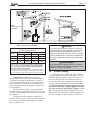
3. Use the fi gures in Table 5 to size the gas inlet
piping from the gas meter to the heater. Check all
local codes for compliance before installing the
heater.
Table 5. Supply Gas Pipe Size Requirements*
Distance from Gas Meter
Heater
Size
0-50 feet
(0-15 m)
50-100 feet
(15-30 m)
100-200 feet
(30-60 m)
in. mm in. mm in. mm
250 1 25 1-1/4 32 1-1/4 32
300 1-1/4 32 1-1/4 32 1-1/2 38
400 1-1/4 32 1-1/2 38 1-1/2 38
Notes:
*1. These numbers are for natural gas (0.65 Sp. Gr.) and
are based on 1/2 inch (3.45 kPa) water column pressure
drop. Check supply pressure with a manometer, and local
code requirements for variations. For LP gas, reduce
pipe diameter by one size, but maintain a minimum
3/4" diameter.
2. Check supply pressure and local code requirements before
proceeding with work.
3. Pipe fi ttings must be considered when determining gas
pipe sizing.
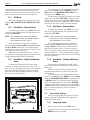
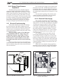
4. Install a sediment trap (drip leg) ahead of the gas
controls. See Figure 9. Fit the trap with a thread-
ed cap which can be removed for cleaning.
5. Install a manual gas shutoff valve for service
and safety. Do not use a restrictive gas cock.
DO NOT USE FLEXIBLE GAS PIPING, it will
restrict the gas fl ow to the heater.
6. Disconnect the heater and its individual shutoff
valve from the gas supply system during pressure
testing of the system at pressures higher than 1/2
pounds per square inch (psi) (3.45 kilopascals
[kPa]). If the test pressure is equal to or less than
1/2 psi (3.45 kPa), close the manual shutoff valve
on the heater during the piping pressure test.
Figure 9. Proper Design for a Sediment Trap/Drip Leg
APPROVED

LXi
™
Pool/Spa Heater Installation and Operation Manual Page 17
7. If the gas supply pressure is less than required,
check for undersized pipe between the meter and
the heater, a restrictive fi tting, or an undersized
gas meter. Gas supply pressures to the heater are
listed in Table 6.
Table 6. Gas Supply Pressure Requirements*
Supply Pressure Minimum Maximum
Natural Gas 5.0 inches W.C.
(1.2 kPa)
10.5 inches W.C.
(2.6 kPa)
LP Gas 11.0 inches W.C.
(2.5 kPa)
14.0 inches W.C.
(3.5 kPa)
Manifold Pressure Nominal
Natural Gas 2.5 inches W.C. (0.6 kPa)
LP Gas 9.0 inches W.C. (2.2 kPa)
NOTE The maximum inlet gas pressure must not
exceed the specifi ed value. The minimum value
listed is for the purpose of input adjustment. Refer
to Table 6.
8. To connect the gas supply line to the heater’s gas
valve, make sure the steel elbow (supplied with
the manifold) is screwed into the inlet side of the
gas valve. The heater is designed so that the gas
supply line may enter through either side of the
heater. Tighten the elbow until the desired orien-
tation is achieved.
CAUTION
Do not overtighten the elbow. Over tightening will
crack the gas valve. Do not use tefl on tape to wrap
the elbow threads.
ATTENTION
Ne serrez pas trop le coude. Vous risqueriez de fi s-
surer la soupape de gaz. N’entourez pas le fi letage
des coudes de ruban à joints.
9. Before operating the heater, test the complete gas
supply system and all connections for leaks using
a soap solution. Do not use an open fl ame.
CAUTION
Some leak test solutions (including soap and water)
may cause corrosion or stress cracking. Rinse the
piping with water after testing.
ATTENTION
Certaines solutions d’essai d’étanchéité (y compris
l’eau et le savon) peuvent causer de la corrosion
ou de la fi ssuration. Rincez les tuyaux à l’eau après
l’essai d’étanchéité.
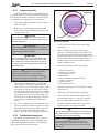
4.2 Manifold Pressure
Confi rm that gas supply pressure is correct. If
the gas supply pressure is less than required, check
for undersized pipe between the meter and the heater,
a restrictive fi tting, or an undersized gas meter. Gas
supply pressures to the heater, when it is operating, are
listed in Table 6.
CAUTION
Manifold gas pressure for the LXi natural gas heat-
ers should be set at 2.5" WC. Propane heaters
should be set to 9" WC.
ATTENTION
La pression du collecteur de pression pour les
systèmes de chauffage au gaz naturel devrait être
de 2.5'’ WC. Pour les sytèmes de chauffage au gaz
propane devrait être de 9'’ WC.
The manifold pressure may be checked by con-
necting a manometer to the pressure port on the outlet
side of the valve. The pressure will be zero when the
heater is not running. When the heater is operating the
manifold gas pressure should be 2.5" WC for natural
gas heaters and 9.0" WC for LP gas heaters.
If the manifold pressure indicated above is not
correct, check the gas train for possible problems.
Check the meter, gas line, gas fi ttings, and gas shut off
for under sizing. Check the gas valve inlet for excess
pipe dope, if all is correct, then it may be necessary to
adjust the gas valve regulator. To adjust the manifold
gas pressure, fi rst remove the slotted cap next to the
inlet pressure port on the inlet side of the gas valve.
Under the slotted cap is a slotted plastic screw which
increases the manifold pressure when turned clock-
wise and decreases the manifold pressure when turned
counterclockwise. After measurements, and adjust-
ments if necessary, have been made, make sure to
replace the 1/8" NPT gas valve plugs on the inlet and
manifold pressure ports, and the cap on the manifold
pressure adjustment screw. It is extremely important
to replace these parts before leaving the installation.
Failure to do so can result in damage to property or in-
jury or death. With the heater fi ring, the pressure must
be within the range shown in Table 6. Also check the
pressure with the heater off.
4.3 Special Precautions for LP Gas
LP Gas is heavier than air and can therefore more
readily collect or “pool” in enclosed areas if provision
for proper ventilation is not made. Installation of pool
heaters in enclosed areas such as pits is not recom-
mended. However, if such an installation is required
be sure to pay special attention to proper ventilation
requirements for LP gas. Locate heaters a safe dis-
tance from LP gas cylinders and fi lling equipment.
Consult the National Fuel Gas Code (NFPA 54 / ANSI
Z223.1, latest edition), the Natural Gas and Propane
Installation Code in Canada (CAN/CSA B149.1, latest
edition), and any other local codes and fi re protection
authorities about specifi c installation restrictions in
your area.

Page 18 LXi
™
Pool/Spa Heater Installation and Operation Manual
Do not install any valve in the piping between the
heater outlet and the pool, unless it is being used as a
diverter valve. For special installations, such as water
connections below the water level of the pool, or for
other questions contact the Technical Service depart-
ment at 1.707.776.8200 ext. 260.
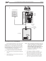
5.3 Automatic Flow Control Valve
The inlet/outlet header of the LXi heater comes
equipped with an automatic fl ow control valve. The
automatic fl ow control valve maintains the proper
fl ow through the heater at rates up to approximately
125 Gallons Per Minute (GPM) (475 liters per minute
[LPM]). If the fi lter system fl ow rate is higher than
approximately 125 GPM (475 LPM), install a manual
bypass valve (see Figure 11), then perform a tempera-
ture rise test (see Section 7.8) and adjust the fl ow using
the bypass valve until the proper temperature rise is
obtained.
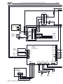
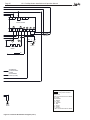
5.4 Reversible Water Connections
The LXi heater is shipped with water connec-
tions on the right side, but can be modifi ed in the fi eld
to provide left-side water connections. This procedure
involves removing the heat exchanger headers and
reinstalling them on opposite ends of the tube assem-
bly. Some of the heater wiring must be disconnected
and re-routed, so this procedure must be done only by
a trained service technician. Heat exchanger reversals
are generally done before the installation of power
and water to the heater. If you need to reverse the heat
exchanger on a previously installed heater be sure that
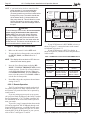
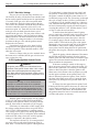
Section 5. Water Connections
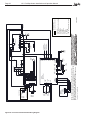
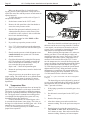
5.1 Water Piping
Figure 10 illustrates typical piping for pool
equipment in pool/spa combination pools. With its
electronic control, the LXi heater is particularly suited
for this type of pool installation.
The heater must be protected from back-siphon-
ing of water, which can result in dry starts. If there is
any chance of back-siphoning, provide a check valve
between the pool and the fi lter pump inlet.
Arrangement of pool system components other
than as illustrated in these diagrams can affect the op-
eration of the heater’s water pressure switch. Location
of the heater above or below the pool water surface
can also affect operation of the switch. In general, the
pressure switch can be adjusted to accommodate this
effect if the heater water connections are no more than
six (6) feet below the pool water surface and no more
than 15 feet above it. See instructions for pressure
switch adjustment (Section 7.7) for more information
about this.
Note that when pool equipment is located below
the pool surface a leak can result in large scale water
loss or fl ooding. Jandy Pool Products, Inc., cannot be
responsible for such water loss or fl ooding or the dam-
age caused by either occurrence.
5.2 Check Valve Installation
Install a check valve in the plumbing between
the pool inlet and the heater if there is any chance of
back-siphoning.
AQUAPURE
Figure 10. Typical Piping Installation

LXi
™
Pool/Spa Heater Installation and Operation Manual Page 19
all electrical power, the gas supply and water supply
have been turned off before starting the procedure.
These instructions have been written to include the
steps needed when reversing the water connections on
an existing installation. If you are reversing the head-
ers on a new installation, some steps will be ignored.
Water connection reversal is illustrated in Figures 11
and 12. Proceed as follows:
1. For an existing installation, drain the heater by
removing the two drain plugs on the inlet/outlet
header and the drain plug on the return header.
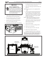
2. Remove the heater front panel (door).
3. Remove the I/O header side cover plates, top and
bottom. See Figure 13.
4. Remove the return header side cover plate. See
Figure 13.
5. Disconnect the blue "HiLimit" two-pin connector
from the Power Interface board in the raceway.
Clip any wire ties attached to the harness. Feed
the "HiLimit" two-pin connector and wiring back
through the way it is routed to the header so that
the harness hangs free from the header, outside of
the cabinet.
6. Disconnect the two "WATER TEMP" tempera-
ture sensor leads from the Power Interface board
in the raceway. Clip any wire ties attached to the
harness. Pull the wires out of the cabinet so that
they hang free from the header, outside of the
cabinet.
7. Disconnect the yellow "Water Press" two-pin
connector from the Power Interface board in
the raceway. Clip any wire ties attached to the
harness. Feed the "Water Press" two-pin connec-
tor and wiring back through the way it is routed
to the water pressure switch so that the harness
hangs free from the water pressure switch, out-
side of the cabinet.
NOTE Be careful not to create any kinks in the water
pressure switch copper tubing when handling
the header.
8. For an existing installation, remove the coupling
nuts from the header and disconnect the water
supply from the heater.
9. Remove the 10 bolts and washers from the inlet/
outlet header and remove the header from the
tube assembly. Leave the spacer in place.
10. Remove the 10 bolts and washers from the return
header and remove the header from the tube as-
sembly. Leave the spacer in place.
11. For an existing installation, remove the tube
gaskets and clean the header's mating surface of
any corrosion or debris. Replace the tube gaskets
with new ones. Do not use any metal tools on the
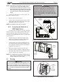
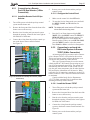
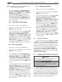
Figure 13. LXi Panel Identifi cation
I/O HEADER SIDE
COVER PLATES
TOP AND BOTTOM
SIDE
SUPPORT
RETURN
HEADER SIDE
COVER PLATE
SIDE
LEFT
REAR
PANEL
TOP
PANEL
REAR VENT
COVER
GRILL
FRONT
PANEL
(DOOR)
DOOR
SUPPORT
SIDE
SUPPORT
SIDE
RIGHT
BASE
Figure 11. Water Connections as Shipped
Figure 12. Water Connections Reversed

Page 20 LXi
™
Pool/Spa Heater Installation and Operation Manual
header surface. Scratches may compromise the
seal integrity.
12. Place the inlet/outlet header over the bolts and
gasketed tubes on the left side of the tube assem-
bly. Align the bolt and tube holes in the header
with the bolts and tubes in the header bar and
slide the assembly together. Make sure the spacer
is in place.
13. Thread on the 10 bolts and washers and hand
tighten.
14. Place the return header over the bolts and gasket-
ed tubes on the right side of the tube assembly.
Align the bolt and tube holes in the header with
the bolts and tubes in the header bar and slide
the assembly together. Make sure the spacer is in
place.
15. Thread on the 10 bolts and washers and hand
tighten.
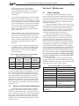
16. Use a torque wrench to tighten the bolts on each
header to four (4) foot-pounds. The bolts must be
tightened in the sequence indicated in Figure 14.
CAUTION
Failure to tighten the header as indicated in step 16
may cause the header to leak or become perma-
nently damaged from warping.
ATTENTION
Si le tuyau collecteur n’est pas serré conformément
aux directives des l'étape 16, il risque d’avoir des
fuites ou de s’endommager de façon permanente.
17. Remove the 3/4 inch button plug located in the
left side panel below the inlet/outlet header and
replace with the 3/4 inch wire grommet from
the right side panel below the return header. The
high limit leads were routed through this grom-
met prior to removal in step 5. Install the 3/4
inch plug in the opening where the 3/4 inch wire
grommet was removed.
18. Route the blue two-pin connector attached to
the high limit switches back to the Power Inter-
face board in the raceway. Reconnect the blue
“HiLimit” two-pin connector to the blue “HiLim-
it” connector on the Power Interface board.
19. Route the wires that attach to the temperature
sensor back to the Power Interface board in the
raceway. Reconnect the wires to the “WATER
TEMP” terminals on the Power Interface board.
20. Route the yellow two-pin connector that connects
to the water pressure switch back to the Power
Interface board in the raceway. Reconnect the
yellow two-pin connector to the yellow “Water
Press” connector on the Power Interface board.
21. Use plastic wire ties to refasten the temperature
sensor, high limit switch and water pressure
switch wires to each other. Bundle the wires near
the control panel and fasten them with a wire tie.
NOTE Be sure that none of the wires are in contact
with a sharp edge or a hot surface.
22. Install the return header side cover plate on the
right side of the unit.
23. Install the I/O header side cover plates, top and
bottom on the left side of the unit.
24. Replace the front panel (door).
5.5 Connections at Heater
The LXi heater has a standard 2" water header
and coupling design. With this feature, only nomi-
nal two inch PVC or CPVC may be connected to the
heater. However, by installing the appropriate pipe
adapters and two short pieces of two inch plastic pipe
(supplied by the installer), any size existing pipe may
be fi tted to the heater.
The LXi heater also comes with a Jandy Sweep
Elbow for increased hydraulic performance and ef-
fi ciency. The sweep elbow also provides the advantage
of its exclusive interface with the Jandy AquaLink
®
RS
temperature sensor.
To install the Jandy Sweep Elbow follow these
instructions:
WARNING
To avoid an electrical shock hazard, which can result
in serious injury or death, ensure that all electrical
power to the system is turned off before approaching,
inspecting or troubleshooting any leaking valves
or plumbing that may have caused other electrical
devices in the surrounding area to get wet.
4
6
5
10
1
8
7
3
2
9
Figure 14. Header Bolt Tightening Sequence
La page est en cours de chargement...
La page est en cours de chargement...
La page est en cours de chargement...
La page est en cours de chargement...
La page est en cours de chargement...
La page est en cours de chargement...
La page est en cours de chargement...
La page est en cours de chargement...
La page est en cours de chargement...
La page est en cours de chargement...
La page est en cours de chargement...
La page est en cours de chargement...
La page est en cours de chargement...
La page est en cours de chargement...
La page est en cours de chargement...
La page est en cours de chargement...
La page est en cours de chargement...
La page est en cours de chargement...
La page est en cours de chargement...
La page est en cours de chargement...
La page est en cours de chargement...
La page est en cours de chargement...
La page est en cours de chargement...
La page est en cours de chargement...
La page est en cours de chargement...
La page est en cours de chargement...
La page est en cours de chargement...
La page est en cours de chargement...
La page est en cours de chargement...
La page est en cours de chargement...
La page est en cours de chargement...
La page est en cours de chargement...
La page est en cours de chargement...
La page est en cours de chargement...
La page est en cours de chargement...
La page est en cours de chargement...
-
 1
1
-
 2
2
-
 3
3
-
 4
4
-
 5
5
-
 6
6
-
 7
7
-
 8
8
-
 9
9
-
 10
10
-
 11
11
-
 12
12
-
 13
13
-
 14
14
-
 15
15
-
 16
16
-
 17
17
-
 18
18
-
 19
19
-
 20
20
-
 21
21
-
 22
22
-
 23
23
-
 24
24
-
 25
25
-
 26
26
-
 27
27
-
 28
28
-
 29
29
-
 30
30
-
 31
31
-
 32
32
-
 33
33
-
 34
34
-
 35
35
-
 36
36
-
 37
37
-
 38
38
-
 39
39
-
 40
40
-
 41
41
-
 42
42
-
 43
43
-
 44
44
-
 45
45
-
 46
46
-
 47
47
-
 48
48
-
 49
49
-
 50
50
-
 51
51
-
 52
52
-
 53
53
-
 54
54
-
 55
55
-
 56
56


dans d''autres langues
- English: Jandy LXI Operating instructions
Documents connexes
-
Jandy AquaLink RS Control Systems Manuel utilisateur
-
-
Jandy 400120 Manuel utilisateur
-
-
-
Jandy TruClear Installation & Operation Manual
-
Jandy H90010 Manuel utilisateur
-
Jandy JVA 2444 Guide d'installation
-
Jandy SMARTSYNC60W Manuel utilisateur
-
Autres documents
-
Pentair Pool Products 250K BTU/HR Installation and User Manual
-
Waterco Electroheat Pool Heat Pump Mode d'emploi
-
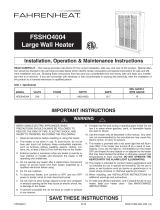 Fahrenheat FSSHO4004 Installation, Operation & Maintenance Instructions Manual
-
Ariston AURES SM 13 240V US Manuel utilisateur
-
-
Aquacal AUTOPILOT 120 Manuel utilisateur
-
DCS DRH-48N Manuel utilisateur
-
LG LZ-H200GBA2.ENWALEU Manuel utilisateur
-
Mr. Heater 9147075 Le manuel du propriétaire
-
Ariston AURES PRO 36 240V US Manuel utilisateur
