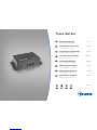
Truma iNet Box Installation Instructions Manual
- Taper
- Installation Instructions Manual
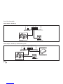
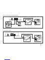
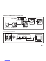
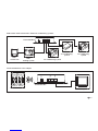
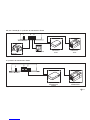
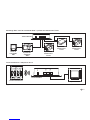
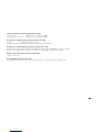
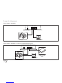
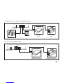
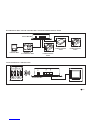
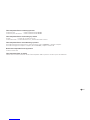
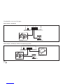
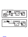
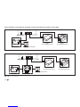
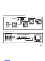
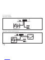
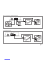
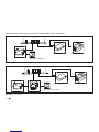
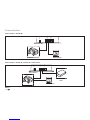
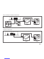
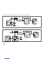
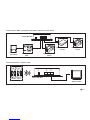
Vous trouverez ci-dessous de brèves informations pour iNet Box. Le boîtier iNet Box est conçu pour contrôler les appareils compatibles iNet via des appareils mobiles en utilisant la communication Bluetooth ou GSM. Il permet de contrôler les systèmes de chauffage et de climatisation Truma, ainsi que les systèmes Alde. Vous pouvez également connecter des appareils compatibles Bluetooth comme le Truma LevelControl. Le boîtier est équipé d'une antenne interne GSM, mais vous pouvez également connecter une antenne externe. Il est essentiel de maintenir une distance de sécurité de 20 cm par rapport aux personnes et d'utiliser correctement les connexions TIN.
Vous trouverez ci-dessous de brèves informations pour iNet Box. Le boîtier iNet Box est conçu pour contrôler les appareils compatibles iNet via des appareils mobiles en utilisant la communication Bluetooth ou GSM. Il permet de contrôler les systèmes de chauffage et de climatisation Truma, ainsi que les systèmes Alde. Vous pouvez également connecter des appareils compatibles Bluetooth comme le Truma LevelControl. Le boîtier est équipé d'une antenne interne GSM, mais vous pouvez également connecter une antenne externe. Il est essentiel de maintenir une distance de sécurité de 20 cm par rapport aux personnes et d'utiliser correctement les connexions TIN.


-
 1
1
-
 2
2
-
 3
3
-
 4
4
-
 5
5
-
 6
6
-
 7
7
-
 8
8
-
 9
9
-
 10
10
-
 11
11
-
 12
12
-
 13
13
-
 14
14
-
 15
15
-
 16
16
-
 17
17
-
 18
18
-
 19
19
-
 20
20
-
 21
21
-
 22
22
-
 23
23
-
 24
24
-
 25
25
-
 26
26
-
 27
27
-
 28
28
-
 29
29
-
 30
30
-
 31
31
-
 32
32
-
 33
33
-
 34
34
-
 35
35
-
 36
36
-
 37
37
-
 38
38
-
 39
39
-
 40
40
-
 41
41
-
 42
42
-
 43
43
-
 44
44
-
 45
45
-
 46
46
-
 47
47
-
 48
48
-
 49
49
-
 50
50
-
 51
51
-
 52
52
-
 53
53
-
 54
54
-
 55
55
-
 56
56
-
 57
57
-
 58
58
-
 59
59
-
 60
60
-
 61
61
-
 62
62
-
 63
63
-
 64
64
-
 65
65
-
 66
66
-
 67
67
-
 68
68
-
 69
69
-
 70
70
-
 71
71
-
 72
72
-
 73
73
-
 74
74
-
 75
75
-
 76
76
-
 77
77
-
 78
78
-
 79
79
-
 80
80
-
 81
81
-
 82
82
-
 83
83
-
 84
84


Truma iNet Box Installation Instructions Manual
- Taper
- Installation Instructions Manual
Vous trouverez ci-dessous de brèves informations pour iNet Box. Le boîtier iNet Box est conçu pour contrôler les appareils compatibles iNet via des appareils mobiles en utilisant la communication Bluetooth ou GSM. Il permet de contrôler les systèmes de chauffage et de climatisation Truma, ainsi que les systèmes Alde. Vous pouvez également connecter des appareils compatibles Bluetooth comme le Truma LevelControl. Le boîtier est équipé d'une antenne interne GSM, mais vous pouvez également connecter une antenne externe. Il est essentiel de maintenir une distance de sécurité de 20 cm par rapport aux personnes et d'utiliser correctement les connexions TIN.
dans d''autres langues
- italiano: Truma iNet Box
- Nederlands: Truma iNet Box
- dansk: Truma iNet Box
Documents connexes
-
Truma Combi 6 Operating Instructions Manual
-
-
Truma VarioHeat Installation Instructions Manual
-
Truma Trumatic E 4000 Operating Instructions Manual
-
-
-
-
-
-