ROBBE MAN F2000 Evolution Assembly And Operating Instructions Manual
- Catégorie
- Jouets télécommandés
- Taper
- Assembly And Operating Instructions Manual
La page est en cours de chargement...

2
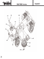
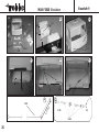
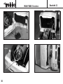
Contenu de la boîte de construction :
• châssis en alu fraisé et alésé sur machines à commande
numérique
• cabine Évolution d'un seul tenant en éléments de pla-
stique moulé
• éléments d'aménagement comme réservoir, garde-boue,
boîtier à batteries, rétroviseurs, essuie-glace et caisson à
air comprimé.
• Éclairage à plusieurs compartiments pour les feux arrière
et les phares en plastique
• vitrage en polycarbonate et aménagement intérieur de la
cabine
• siège du conducteur et du passager
• pneumatiques à chambre sur jantes au format européen
et roue de secours
• essieu avant en fonte d'aluminium
• essieu arrière avec différentiel sur pignons coniques
• cardans avec entraîneurs et petits éléments
• pièces de mise en place de l'ensemble de réception
• éléments en plastique estampé pour la benne
• feuillet d'autocollants de décoration en couleurs et notice
illustrée en plusieurs langes
Caractéristiques techniques :
échelle de reproduction: 16e
longueur: approx. 385 mm
largeur: approx. 158 mm
hauteur: approx. 187 mm
empattement: approx. 225 mm
pincement: approx. 128 mm
poids (avec équipement
de réception): approx. 2200 g
Recommandations générales
Les éléments repérés par n.c. dans les listes des pièces ne
sont pas contenus dans la boîte de construction.
L’identification des éléments fraisés est facilité par les sché-
mas „0“ cf. pages 40 et 41. Repérer les éléments
estampés en conséquence et les percer avant de les déta-
cher de leur support.Gabarits nécessaires cf. page 43.
Éléments indispensables ou appropriés:cf. feuillet joint.
Outillage et accessoires: cf. catalogue général robbe.
Kit contents:
• CNC-machined, bored aluminium frame chassis moulded
plastic parts
• External items such as fueltank, mudguards, battery box,
mirrors, windscreen wipers and compressed air tank
• Plastic multi-chamber lamp clusters for rear lights and
front headlights
• Polycarbonate screens and driver’s cab insert
• Driver’s seat and passenger seat
• Air-chamber tyres on Euro wheels, plus spare wheel
• Pressure-cast aluminium front axle
• Rear axle with bevel gear differential
• Articulated shaft with shaft driver and small items
• Small parts for RC installation
• Die-cut components for tipper body
• Multi-colour decal sheet and illustrated, multi-lingual buil-
ding instructions
Specification:
Scale: 1:16
Length: approx. 385 mm
Width: approx. 158 mm
Height: approx. 187 mm
Wheelbase: approx. 225 mm
Track: approx. 128 mm
Weight
(incl. RC fittings): approx. 2200 g
General notes
Parts marked N.I. in the parts list are not included in the
kit.
The identification drawings „0“ on the pages 40 and 41
helps you to identify the machined parts. Mark the numbers
on the parts and drill holes at the marked points before you
separate the parts from the sheet.
Templates see pags 43.
Essential and optional accessories:
See separate sheet
Tools and aids to building: see main Robbe catalogue
MAN F2000 Evolution
No. 3339
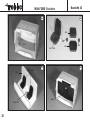
Inhalt des Montagekastens:
• CNC-gefrästes und gebohrtes Alu-Rahmenchassis
• Einteiliges Evolution-Fahrerhaus aus KU-Gußteilen
• Anbauteile wie z.B. Tank, Kotflügel, Batteriekasten,
Spiegel, Scheibenwischer und Druckluftkessel
• Mehrkammerleuchten für Rücklichter und
Frontscheinwerfer aus Kunststoff
• Polycarbonatscheiben und Fahrerhauseinsatz
• Fahrer- und Beifahrersitz
• Hohlkammerreifen auf Euro-Felgen, sowie Ersatzrad
• Alu-Druckguß-Vorderachse
• Hinterachse mit Kegelraddifferential
• Kardanwelle mit Mitnehmer und Kleinteilen
• Kleinteile für RC-Einbau
• Stanzteile für Kipperaufbau
• Mehrfarbiger Dekorbogen und mehrsprachige, bebilderte
Bauanleitung
Technische Daten
Maßstab: 1:16
Länge: ca. 385 mm
Breite: ca. 158 mm
Höhe: ca. 187 mm
Radstand: ca. 225 mm
Spurweite: ca. 128 mm
Gewicht
(mit RC-Ausrüstung): ca. 2200 g
Allgemeine Hinweise
In den Baustufenstücklisten mit n. e. gekennzeichnete
Positionen sind nicht im Lieferumfang enthalten.
Das Auffinden der Frästeile erleichtern die
Identifikationszeichnungen „0“ auf den Seiten 40 und 41.
Stanzteile entsprechend kennzeichnen und bohren, dann
erst austrennen.
Schablone siehe Seite 43.
Erforderliches bzw. geeignetes Zubehör:
Siehe Beilageblatt
Werkzeuge und Hilfsmittel:
Siehe robbe Hauptkatalog

L
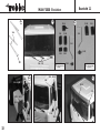
Consignes générales pour l’assemblage
Avant d’entreprendre la construction, familiarisez-vous
avec les diverses étapes de montage en lisant le texte
de la notice au regard de la liste des pièces, des schémas
et des fotos.
L’ordre de montage est indiqué en règle générale par la
numérotation des pièces sur les schémas, les listes de
pièces et les textes de la notice.
Le numéro précédant le point correspond au stade de
montage en cours alors que le numéro qui suit le point est
celui de la pièce proprement dite.
Les données directionnelles sont toujours à considérer
dans le sens de la marche, vu d’en haut.
Freiner toutes les liaisons vissées métal-
métal avec un produit spécifique, p. e. Loctite,
particulièrement dans le secteur de l’entraînement et lors-
que cela est signalé sur le schéma correspondant.
Dégraisser les vis et les filets avant d’appliquer le liquide
de freinage des vis.
Colles recommandées:
colle cyanoacrylate (monocomposant) et colle deux-compo-
sants sur une base de polyester.
Pour les coller les éléments doivent être exempts de
peinture!
Mise en peinture:
Installer les éléments à peindre pour essai avant de les
peindre, si nécessaire, les ajuster. Avant de les peindre
dégraisser les éléments à peindre avec de l’alcool ou de
l’esprit de vin. Apprêter les pièces à peindre.
Employer des peintures à base acrylique ou de résine
synthétique.
Mise en place des autocollants de décoration
Avant d'appliquer les autocollants, tamponner la surface
destinée à les recevoir à l'garde boue d'une solution très
diluée de produit pour la vaisselle. Il est ainsi possible de
déplacer les autocollants brièvement pour corriger leur
position avant de les tamponner dans leur position
définitive.
MAN F2000 Evolution
No. 3339
3
!!
ACHTUNG! Wir empfehlen, die Bauanleitung für spätere Wartungs- und Demontagearbeiten aufzuheben!
IMPORTANT: We recommend that you store the building instructions carefully in case you need to dismantle the model for maintenance.
IMPORTANT! Conservez ce notice de montage et d´utilisation pour toutes les réparations ultérieures!
General notes on assembling the model
Read right through the instructions before you start
construction, referring to the drawings, the photos and the
parts lists, so that you have a clear idea of how the model
goes together.
In general terms the sequence of assembly
corresponds to the part numbers in the drawings, parts
lists and instructions. The number before the point indica-
tes the Stage of construction, the number after the point the
individual component.
Directions such as „right-hand“ are always as seen
from the top rear of the model, looking forward.
Secure all metal-metal screwed joints
with thread-lock fluid.
This applies in particular to joints in the power train, and
wherever stated in the drawings.
De-grease screws and other threaded parts before applying
thread-lock fluid.
Adhesives:
Cyano-acrylate („cyano“) (one-shot glue) and polyester-
based two-pack resin adhesives.
Remove paint from the joint areas of all parts.
Painting:
Trial-fit the parts to be painted before painting them and
trim if necessary.
Parts which have to be painted must be cleaned with
alcohol or white spirit beforehand to remove all traces of
grease.
Apply primer to the parts to be painted.
Use acrylic or synthetic enamel paints only.
Applying the self-adhesive decals
Moisten the surface of the model with a weak solution of
washing-up liquid before applying the decal.
This allows you a little time to slide the decal into correct
position before smoothing it down.
L
Allgemeine Hinweise für den Zusammenbau
Verschaffen Sie sich vor Baubeginn einen Überblick
über die jeweilige Baustufe anhand der Zeichnungen und
Fotos, der Stücklisten und der Anleitungstexte.
Die Reihenfolge des Zusammenbaus ergibt sich im
wesentlichen aus den Positionsnummern in den
Zeichnungen, Stücklisten und Anleitungstexten.
Die Nummer vor dem Punkt gibt die Baustufe, die Nummer
hinter dem Punkt gibt das betreffende Bauteil an.
Richtungsangaben sind immer in Fahrtrichtung vor-
wärts, von oben zu sehen!
Sichern Sie alle Metall-Metall
Schraubverbindungen mit einem flüssigen
Schraubensicherungsmittel, z. B. Loctite,
insbesondere im Antriebsstrang und wenn dies in der
Zeichnung vermerkt ist.
Entfetten Sie Schrauben und Gewinde vor dem
Aufbringen der Schraubensicherung!
Empfohlene Klebstoffe:
Sekundenkleber (Einkomponentenkleber) und
Zweikomponentenkleber auf Polyesterbasis (Stabilit
Express)
Zu verklebende Teile müssen frei von Lack sein!
Lackierung:
Vor dem Lackieren sollten Sie die Teile
probeweise montieren und ggf. anpassen.
Entfetten Sie die zu lackierenden Teile vor dem
Lackieren mit Alkohol oder Spiritus.
Grundieren Sie die zu lackierenden Teile.
Verwenden Sie Acryl- oder Kunstharzlacke.
Anbringen der Dekorbogen:
Benetzen Sie die zu beklebenden Flächen mit einer
schwachen Spülmittellösung, bevor Sie den Dekorbogen
aufkleben.
Der Dekorbogen kann so zur Korrektur noch kurzzeitig
verschoben, endgültig positioniert und geglättet werden.
L
La page est en cours de chargement...

Übersicht über die Baustufen Seite
Baustufe 1: Vormontage Chassis 4, 5
Baustufe 2: Vorderachse 6-9
Baustufe 3: Hinterachse 10-13
Baustufe 4: Montage Karosserie- und Motorhalter 14, 15
Baustufe 5: Antrieb 16, 17
Baustufe 6: Kotflügel und Rückleuchten 18, 19
Baustufe 7: Funktionsprobe der RC-Einbauteile 20, 21
Baustufe 8: Anbauteile am Chassis 22-25
Baustufe 9: Zusammenbau Fahrerhaus, Tank 26, 27
Baustufe 10: Innenausbau Fahrerhaus 28, 29
Baustufe 11: RC-Einbau, Montage Fahrerhaus, 30-33
Abschließende Arbeiten
Baustufe 12: Die Kippmulde 34-37
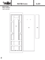
Baustufe 1: Vormontage Chassis
Pos.-Nr. Bezeichnung Maße (mm) Anzahl
1.1 Leiterrahmen 1
1.2 Blattfeder, vorn 2
1.3 Blattfeder, hinten rechts 1
1.4 Blattfeder, hinten links 1
1.5 Blattfederhalter 8
1.6 Zylinderschraube M3 x 16 8
1.7 U-Scheibe ø 3,2 innen 8
Montage der Blattfedern (Pos. 1.1 - 1.7)
- Blattfedern 1.2 (vorne) mit Blattfederhaltern 1.5 sowie
Blattfedern hinten 1.3 - 1.4 mit Blattfederhaltern 1.5 mit
Zylinderschrauben 1.6 und Unterlegscheiben 1.7 an
den Leiterrahmen 1.1 schrauben
HINWEIS:
Auf die richtige Seitenzuordnung der hinteren
Blattfedern achten!
Zylinderschrauben 1.6 mit flüssigem
Schraubensicherungsmittel sichern!
Summary of Stages of construction page
Stage 1: Initial chassis assembly 4, 5
Stage 2: Front axle 6-9
Stage 3: Rear axle 10-13
Stage 4: Bodywork holder and motor mount 14, 15
Stage 5: Power system 16, 17
Stage 6: Mudguards and rear light clusters 18, 19
Stage 7: Checking the RC installation components 20, 21
Stage 8: External chassis fittings 22-25
Stage 9: Assembling the driver’s cab and fueltank 26, 27
Stage 10:Internal driver’s cab fittings 28, 29
Stage 11:RC installation, installing the driver’s cab, 30-33
final work
Stage 12:The tipper body 34-37
Stage 1: Initial chassis assembly
Part No. Description Size (mm) No. off
1.1 Ladder frame 1
1.2 Front leaf spring 2
1.3 Rear R.H. leaf spring 1
1.4 Rear L.H. leaf spring 1
1.5 Leaf spring holder 8
1.6 Cheesehead screw M3 x 16 8
1.7 Washer 3.2 I.D. 8
Fitting the leaf springs (parts 1.1 - 1.7)
- Fix the front leaf springs 1.2 and the rear leaf springs
1.3 - 1.4 to the ladder frame 1.1 using the leaf spring
holders 1.5, cheesehead screws 1.6 and washers 1.7.
NOTE:
Note that the rear leaf springs are handed (different
right and left). Secure the cheesehead screws 1.6 with
thread-lock fluid.
Vue d’ensemble de stades de construction page
Stade 1: montage préliminaire du châssis 4, 5
Stade 2: montage préliminaire du châssis 6-9
Stade 3: essieu arrière 10-13
Stade 4: support-carrosserie et support-moteur 14, 15
Stade 5: entraînement 16, 17
Stade 6: garde boues et feux arrière 18, 19
Stade 7: essai de fonctionnement des 20, 21
éléments de l’ensemble de réception
Stade 8: aménagement du châssis 22-25
Stade 9: assemblage de la cabine 26, 27
Stade 10: aménagement intérieur de la cabine 28, 29
Stade 11: montage de l’ensemble de réception 30-33
montage de la cabine, travaux de finition
Stade 12: montage de la benne 34-37
Stade 1: montage préliminaire du châssis
n° désignation cotes (mm) nbre
1.1 châssis 1
1.2 ressort à lames, avant 2
1.3 ressort à lame arrière droit 1
1.4 ressort à lame arrière gauche 1
1.5 support de ressort à lame 8
1.6 vis à tête cylindrique M 3 x 16 8
1.7 rondelle ø 3,2 intér. 8
Montage des ressort à lame (n° 1.1 à 1.7)
- Visser les ressorts à lame 1.2 avant aux supports 1.5
et les ressorts à lame arrière 1.3-1.4 aux supports 1.5
avec les vis à tête cylindrique 1.6 et les rondelles 1.7
au châssis 1.1.
À NOTER:
veiller à la bonne disposition latérale des ressorts à
lame arrière! Freiner les vis à tête cylindrique 1.6 avec
un liquide spécifique !
MAN F2000 Evolution
Baustufe 1
5

MAN F2000 Evolution
Baustufe 2
6
L
2.9
2.9
2.10
2.11
2.12
2.7
2.3
2.2
2.1
2.4
2.4
2.6
2.5
2.13
2.14
2.13
2.8
2a 2b

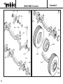
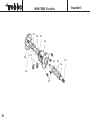
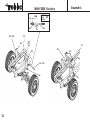
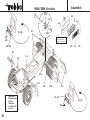
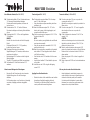
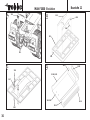
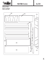
Stage 2: Front axle
Part No. Description Size (mm) No. off
2.1 Plain bushes 5 Ø x 11 Ø x 3 4
2.2 Wheel bearer 2
2.3 Wheel axle 5 Ø x 24 2
2.4 Front axle 2
2.5 Bush 4
2.6 Cheesehead screw M2.5 x 8 4
2.7 Washer ø 8 x 5 x 0,5 2
2.8 Dowel pin 2 Ø x 12 2
2.9 Front wheel driver 2
2.10 Hexagon nut M5 2
2.11 Tyre 2
2.12 Tyre 2
2.13 Front hub cap 2
2.14 Hex-head screw M1.6 x 8 20
2.15 Front leaf spring 2
2.16 Cheesehead screw M3 x 5 4
2.17 Shakeproof washer 3.2 O.D. 4
2.18 Servo mount bracket 2
2.19 Steering servo 1 N.I.
2.20 Servo output lever (with servo) 1
2.21 Cheesehead screw M2 x 10 2
2.22 Hexagon nut M2 3
2.23 Ball-link 16.5 4
2.24 Flanged ball 5 Ø 4
2.25 Trackrod 2 x M2 x 60 1
2.26 Steering pushrod 2 x M2 x 40 1
2.27 Self-tapping screw 2.2 Ø x 11 3
2.28 Cheesehead screw M2 x 10 1
2.29 Self-tapping screw 2.2 Ø x 6,5 2
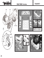
Preparation:
- Prime the wheels 2.12, paint them and allow to dry
Preparing the front axle (parts 2.1 - 2.14)
2a Press the plain bushes 2.1 into the wheel bearers 2.2
and fit the wheel axles 2.3 through them.
- Fit the bushes 2.5 in the front axle 2.4.
- Attach the wheel bearers 2.2 to the front axle 2.4
using the cheesehead screws 2.6.
- Fit the washers 2.7 on the wheel axles 2.3, insert the
dowel pins 2.8 and secure them with thread-lock fluid.
- Fit the front wheel drivers 2.9 on the axles 2.3 and
secure them with the hexagon nuts 2.10.
2b Pull the tyres 2.11 onto the painted wheel rims. Secure
the tyres with a little cyano glue.
- Press the hub caps 2.13 into the wheels 2.12.
- Attach the wheels to the wheel drivers 2.9 using the
hex-head screws 2.14.
- Use a socket spanner AF 3,2.
Stade 2: montage préliminaire du châssis
n° désignation cotes (mm) nbre
2.1 palier lisse ø 5 x ø 11 x 3 4
2.2 support de roue 2
2.3 axe de roue ø 5 x 24 2
2.4 axe avant 1
2.5 palier 4
2.6 vis à tête cylindrique M 2,5 x 8 4
2,7 rondelle ø 8 x 5 x 0,5 2
2.8 goupille ø 2 x 12 2
2.9 adaptateur de jante, avant 2
2.10 écrou six pans M/5 2
2.11 pneumatique 2
2.12 jantes 2
2.13 enjoliveur, avant 2
2.14 vis six pans M 1,6 x 8 20
2.15 ressort à lame, avant 2
2.16 vis à tête cylindrique M 3 x 5 4
2.17 rondelle-éventail ø 3,2 intér. 4
2.18 équerre support-servo 2
2.19 servo de direction 1 n.c.
2.20 palonnier de servo (livré avec le servo) 1
2.21 vis à tête cylindrique M2 x 10 2
2.22 écrou six pans M2 3
2.23 rotule 16,5 4
2.24 biellette avec épaulement ø 5 4
2.25 barre d’accouplement 2 x M 2 x 80 1
2.26 tringle de direction 2 x M 2 x 40 1
2.27 vis autotaraudeuse ø 2,2 x 11 3
2.28 vis à tête cylindrique M2 x 10 1
2.29 vis autotaraudeuse ø 2,2 x 6,5 2
Travaux préliminaires :
- Apprêter les jantes 2.12, les peindre et les laisser
sécher
Assemblage de l’essieu avant (n° 2.1 à 2.14)
2a Engager les paliers lisse 2.1 dans le support de
roue 2.2 et y engager les axes de roue 2.3.
- Munir l’axe avant 2.4 des paliers 2.5.
- Fixer les supports de roue 2.2 à l’axe avant 2.4 avec
les vis à tête cylindrique 2.6.
- Glisser les rondelles 2.7 sur les axes de roue 2.3.
Planter les goupilles 2.8 et les freiner avec un produit
adéquat. Planter l’adaptateur de jante 2.9 sur l’axe de
roue 2.3 et le fixer avec l’écrou six pans 2.10.
2b Enfiler les pneumatiques 2.11 sur les jantes peintes
2.12 et les y fixer avec un peu de colle cyanoacrylate.
- Planter les enjoliveurs 2.13 sur les jantes 2.12.
- Visser les roues avec les vis six pans 2.14 aux
adaptateurs de jante 2.9.
- Utiliser le clé à douille taille 3,2.
MAN F2000 Evolution
Baustufe 2
7
Baustufe 2: Vorderachse
Pos.-Nr Bezeichnung Maße (mm) Anzahl
2.1 Gleitlager ø 5 x ø 11 x 3 4
2.2 Radträger 2
2.3 Radachse ø 5 x 24 2
2.4 Vorderachse 1
2.5 Lager 4
2.6 Zylinderschraube M2,5 x 8 4
2.7 U-Scheibe ø 8 x 5 x 0,5 2
2.8 Zylinderstift, ø 2 x 12 2
2.9 Felgenadapter, vorn 2
2.10 Sechskantmutter M5 2
2.11 Reifen 2
2.12 Felgen 2
2.13 Radkappen, vorn 2
2.14 Sechskantschraube M1,6 x 8 20
2.15 Blattfeder, vorn 2
2.16 Zylinderschraube M3 x 5 4
2.17 Fächerscheibe ø 3,2 innen 4
2.18 Servo-Haltewinkel 2
2.19 Lenkservo 1 n. e.
2.20 Servohebel (im Lieferumfang Servo) 1
2.21 Zylinderschraube M2 x 10 2
2.22 Sechskantmutter M2 3
2.23 Kugelkopf 16,5 4
2.24 Kugel mit Bund ø 5 4
2.25 Spurstange 2 x M2 x 80 1
2.26 Lenkgestänge 2 x M2 x 40 1
2.27 Blechschraube ø 2,2 x 11 3
2.28 Zylinderschraube M2 x 10 1
2.29 Blechschraube 2,2 x 6,5 2
Vorbereitende Arbeiten:
- Felgen 2.12 grundieren, lackieren und trocknen lassen
Zusammenbau der Vorderachse (Pos. 2.1 - 2.14)
2a Gleitlager 2.1 in Radträger 2.2 eindrücken und
Radachsen 2.3 einschieben.
- Vorderachse 2.4 mit Lagern 2.5 versehen.
- Radträger 2.2 mit Zylinderschrauben 2.6 an der
Vorderachse 2.4 befestigen.
- U-Scheiben 2.7 auf Radachsen 2.3 schieben,
Zylinderstifte 2.8 einstecken und mit flüssigem
Schraubensicherungsmittel sichern!
- Felgenadapter 2.9 auf Radachse 2.3 stecken und mit
Sechskantmutter 2.10 befestigen.
2b Reifen 2.11 auf lackierte Felgen 2.12 aufziehen und
mit wenig Sekundenkleber sichern.
- Radkappen 2.13 in Felgen 2.12 einsetzen.
- Räder mit Sechskantschrauben 2.14 an den
Felgenadaptern 2.9 verschrauben.
- Steckschlüssel SW 3,2 verwenden.
La page est en cours de chargement...

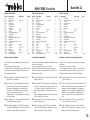
Montage der Vorderachse (Pos. 2.15 - 2.17)
2c Vorderachse 2.1 - 2.14 und Blattfedern
2.15 mit Zylinderschrauben 2.16 und Fächerscheiben
2.17 an den Blattfedern 1.2 verschrauben.
Einbau des Lenkservos (Pos. 2.18 - 2.29)
HINWEIS
Bei Verwendung anderer als der vorgesehenen
RC-Komponenten sind Maßdifferenzen entsprechend
auszugleichen!
- Servo 2.19 mit Gummitüllen und Buchsen versehen.
- Servo-Haltewinkel 2.18 mit Zylinderschrauben 2.21
und Sechskantmuttern 2.22 am Lenkservo 2.19
verschrauben.
2d Servo in Neutralstellung bringen.
Steuerscheibe des Servos durch den beschnittenen
Servohebel 2.20 ersetzen und gemäß Zeichnung
montieren.
- Kugeln mit Bund 2.24 in die Kugelköpfe 2.23
eindrücken.
2e Je 2 Kugelköpfe 2.23 mit 2.24 auf die Spurstange 2.25
und das Lenkgestänge 2.26 aufdrehen und
auf die angegebenen Längen einstellen.
2f Spurstange 2.25 und Lenkgestänge 2.26 an den
Radträgern 2.2 mit Schrauben 2.27 verschrauben.
- Lenkgestänge 2.26 mit Zylinderschraube 2.28 und
Sechskantmutter 2.22 am Servohebel 2.20
verschrauben.
- Servo an den Servo-Haltewinkeln 2.18 gemäß
Zeichnung, Position „A“,mit Blechschrauben 2.29 am
Leiterrahmen 1.1 verschrauben.
Installing the front axle (parts 2.15 - 2.17)
2c Fix the assembled front axle 2.1 - 2.14 to the leaf
springs 1.2 using the secondary leaf springs 2.15, the
cheesehead screws 2.16 and the shake-proof washers
2.17.
Installing the steering servo (parts 2.18 - 2.29)
NOTE
If you are using RC system units other than those recom-
mended you may have to make allowance for minor diffe-
rences in component sizes.
- Press the rubber grommets and spacer sleeves into
the servo 2.19.
- Fix the servo brackets 2.18 to the steering servo 2.19
using the cheesehead screws 2.21 and hexagon nuts
2.22.
2d Set the transmitter sticks to neutral.
Cut down the servo output lever 2.20 as shown.
Remove the servo output disc and fit the lever in its
place as shown in the drawing..
- Press the flanged balls 2.24 into the ball-links 2.23.
2e Screw two ball-links 2.23 / 2.24 on the ends of the
trackrod 2.25 and the steering pushrod 2.26, and set
the rods to the stated lengths.
2f Attach the trackrod 2.25 and the steering pushrod 2.26
to the wheel bearers 2.2 using the self-tapping screws
2.27.
- Fix the steering pushrod 2.26 to the servo output arm
2.20 using the cheesehead screw 2.28 and the
hexagon nut 2.22
- Fix the servo mounting brackets 2.18 to the ladder
frame 1.1 as shown in detail „A“ in the drawing, using
the self-tapping screws 2.29.
Montage de l’axe avant (n° 2.15 à 2.17)
2c Visser l’axe avant monté 2.1 - 2.14 avec les ressorts à
lame 2.15 à l’aide des vis à tête cylindrique 2.16 et
des rondelles-éventail 2.17 sur les ressorts à lame 1.2.
Mise en place du servo de direction (n° 2.18 à 2.29)
À NOTER:
Si vous utilisez d’autres éléments de l’ensemble de récepti-
on que ceux qui sont recommandés, ajuster personnelle-
ment les différences de cote.
- Munir le servo 2.19 des silentblocs et des manchons
- Visser l’équerre de maintien du servo 2.18 avec les vis
à tête cylindrique 2.21 et les écroux six pans 2.22 sur
le servo de direction 2.19.
2d Les manches d´émetteur se trouvent en neutre.
Remplacer le palonnier circulaire par le palonnier 2.20
coupé et le fixer comme mentionné sur le schéma.
- Engager les biellettes à épaulement 2.24 dans le
rotules 2.23
2e Visser chaque fois 2 rotules 2.23 avec 2.24 sur la
barre d’accouplement 2.25 et la tringle de direction
2.26 et les régler à la longueur indiquée.
2f Fixer la barre d’accouplement 2.25 et la tringle de
direction 2.26 avec les vis autotaraudeuses 2.27 aux
supports de roue 2.2.
- Visser la tringle de direction 2.26 au palonnier du
servo 2.20 avec le vis à tête cylindrique et l´écrou six
pans.
- Selon les indications du schéma visser le servo à
l’équerre de maintien 2.18 avec les vis
autotaraudeuses 2.29, position „A“ sur le châssis 1.1.
MAN F2000 Evolution
Baustufe 2
9

MAN F2000 Evolution
Baustufe 3
10
3.1
3.2
3.6
3.5
3.1
3.4
3.1
3.7
3.3
3.2
3.1
3.3

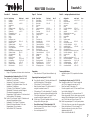
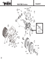
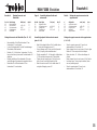
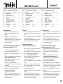
Stage 3: Rear axle
Part No. Description Size (mm) No. off
3.1 Plain bushes 6 Ø x 10 x 3 4
3.2 Spacer washer 6.2 / 10 Ø x 3 4
3.3 Half-shaft 6 Ø x 67 2
3.4 Differential 1
3.5 Circlip 2.3 I.D. 2 + 2 (spares)
3.6 Bevel gear, 29-tooth 1
3.7 Countersunk screw M2 x 4 4
3.8 Axle shell 2
3.9 Drive shaft 1
3.10 Plain bushes 5 Ø x 11 Ø 3 2
3.11 Pinion, 10-tooth 1
3.12 Grubscrew M3 x 3 1
3.13 Self-tapping screw 2.2 Ø x 16 4
3.14 Self-tapping screw 2.2 Ø x 6.5 6
3.15 Sealing plug 6 Ø x 10 Ø x 12 1
3.16 Socket-head cap screw M3 x 20 4
3.17 Rear leaf spring 2, rear 2
3.18 Spacer washer ø 3,2 x ø 6 x 5 4
3.19 Shakeproof washer 3.2 I.D. 4
3.20 Hexagon nut M3 4
3.21 Tyre 4
3.22 Wheel 4
3.23 Rear wheel driver 2
3.24 Hex-head screw M1.6 x 8 20
3.25 Washer 8 x 5I.D. x 0.5 2
3.26 Dowel pin 2 Ø x 12 2
3.27 Shakeproof washer 4.3 I.D. 2
3.28 Hexagon nut M4 2
3.29 Rear hub cap Ø 16 x 12 2
Preparation:
- Prime the wheels 3.22, paint them and allow to dry.
Assembling the rear axle differential (parts 3.1 - 3.7)
- Slip one of the plain bushes 3.1, two spacer washers
3.2 and a second bush 3.1 onto each of the
half-shafts 3.3.
- Slide the prepared half-shafts into the differential 3.4
and snap the circlips 3.5 into place.
- Fix the bevel gear 3.6 to the differential housing using
the countersunk screws 3.7.
Stade 3: essieu arrière
n° désignation cotes (mm) nbre
3.1 palier lisse ø 6 x ø 10 x 3 4
3.2 rondelle-entretoise ø 6,2 x ø 10 x 3 4
3.3 demi-arbre ø 6 x 67 2
3.4 différentiel 1
3.5 bague d’arrêt ø 2,3 intér. 2 + 2 (rempl.)
3.6 pignon conique 29 dents 1
3.7 vis à tête fraisée M2 x 4 4
3.8 demi-axe 2
3.9 arbre d’entraînement 1
3.10 palier lisse ø 5 x ø 11 x 3 2
3.11 pignon 10 dents 1
3.12 vis sans tête M 3 x 3 1
3.13 vis autotaraudeuse ø 2,2 x 16 4
3.14 vis autotaraudeuse ø 2,2 x 6,5 6
3.15 capuchon ø 6 x ø 10 x 12 1
3.16 vvis à tête cylindrique
six pans creux M 3 x 20 4
3.17 ressort à lame 2, arrière 2
3.18 rondelle entretoise ø 3,2 x ø 6 x 5 4
3.19 rondelle-éventail ø 3,2 intér. 4
3.20 écrou six pans M 3 4
3.21 pneumatique 4
3.22 jante 4
3.23 adaptateur de jante arrière 2
3.24 vis six pans M1,6 x 8 20
3.25 rondelle ø 8 x 5 x 0,5 2
3.26 goupille ø 2 x 12 2
3.27 rondelle-éventail ø4,3 intér. 2
3.28 écrou six pans M4 2
3.29 enjoliveur, arrière ø 16 x 12 2
Travaux préliminaires :
- Apprêter les jantes 3.22, les peindre et les
laisser sécher.
Assemblage du différentiel de l’essieu arrière
(n° 3.1 à 3.7)
- Glisser chaque fois 1 palier lisse 3.1, 2 rondelles
3.2 et un autre palier lisse 3.1 sur les demi-arbres 3.3
- Planter les demi-arbres équipés dans le différentiel 3.4
et laisser s’enclencher les bagues d’arrêt 3.5.
- Visser le pignon 3.6 au carter du différentiel avec les
vis à tête fraisée 3.7.
MAN F2000 Evolution
Baustufe 3
11
Baustufe 3: Hinterachse
Pos.-Nr. Bezeichnung Maße (mm) Anzahl
3.1 Gleitlager ø 6 x ø 10 x 3 4
3.2 Distanzscheibe ø 6,2 x ø 10 x 3 4
3.3 Halbwelle ø 6 x 67 2
3.4 Differential 1
3.5 Sicherungsscheibe ø 2,3 innen 2 + 2 (Ers.)
3.6 Kegelrad, 29Z 1
3.7 Senkkopfschraube M2 x 4 4
3.8 Achshälfte 2
3.9 Antriebswelle 1
3.10 Gleitlager ø 5 x ø 11 x 3 2
3.11 Ritzel, 10Z 1
3.12 Madenschraube M3 x 3 1
3.13 Blechschraube ø 2,2 x 16 4
3.14 Blechschraube ø 2,2 x 6,5 6
3.15 Verschlußstopfen ø 6 x ø 10 x 12 1
3.16 Zylinderschraube M3 x 25 4
mit Innensechskant
3.17 Blattfeder 2, hinten 2
3.18 Distanzstück ø 3,2 x ø 6 x 5 4
3.19 Fächerscheibe ø 3,2 innen 4
3.20 Sechskantmutter M3 4
3.21 Reifen 4
3.22 Felge 4
3.23 Felgenadapter hinten 2
3.24 Sechskantschraube M1,6 x 8 20
3.25 U-Scheibe ø 8 x 5 x 0,5 2
3.26 Zylinderstift ø 2 x 12 2
3.27 Fächerscheibe ø 4,3 innen 2
3.28 Sechskantmutter M4 2
3.29 Radkappe, hinten ø 16 x 12 2
Vorbereitende Arbeiten:
- Felgen 3.22 grundieren, lackieren und trocknen lassen.
Zusammenbau des Hinterachsdifferentials
(Pos. 3.1 - 3.7)
- Je 1 Gleitlager 3.1, zwei Distanzscheiben 3.2 und ein
weiteres Gleitlager 3.1 auf die Halbwellen 3.3 schie-
ben.
- Bestückte Halbwellen in das Differential 3.4 stecken
und Sicherungsscheiben 3.5 einrasten lassen.
- Kegelrad 3.6 mit Senkkopfschrauben 3.7 am
Differentialgehäuse verschrauben.

MAN F2000 Evolution
Baustufe 3
12
3.3
3.24
3.22
3.21
3.23
3.27 3.28
3.29
L
3.10
3.12
3.11
3.8
3.9
3.14
3.4
3.15
3.8
3.14
3.13
3.1 - 3.7
L
3.23
3.17
3.17
3.20
3.19
3.25
1.4
3.26
3.18
3.16
3.14
3a
3b
3c

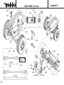
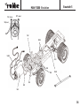
Installing the differential (parts 3.8 - 3.15)
3a Place the assembly 3.1 - 3.7 in one axle shell 3.8.
- Fit the plain bushes 3.10 and pinion 3.11 on the drive
shaft 3.9 and secure it with the grubscrew 3.12;
do not tighten the grubscrew fully at this stage.
- Place the assembly 3.9 - 3.12 in the prepared axle
shel 3.8.
- Checking the system:
Rotate the drive shaft 3.9, and the half-shafts 3.3
should rotate easily.
- When you are satisfied, apply a drop of thread-lock
fluid to the grubscrew 3.12 and tighten it fully.
- Lubricate the bevel gears and bearings with
precision grease.
- Place the second axle shell 3.8 on top and fix the
shellstogether with the self-tapping screws 3.13 and
3.14.
- Press the sealing plug 3.15 into place.
- Place the self-tapping screws 3.14 to the vacant holes
in the axle shells 3.8
Installing the rear axle (parts 3.16 - 3.20)
3b Fix the assembled rear axle 3.1 - 3.15 to the leaf
springs 1.3 and 1.4 using the secondary leaf springs
3.17, the socket-head cap screws 3.16, the spacer
washer 3.18, the shakeproof washers 3.19 and the
hexagon nuts 3.20.
Fitting the wheels (parts 3.21 - 3.29)
3c Pull the tyres 3.21 onto the painted wheels 3.22 and
secure them with a little cyano glue.
- Fix the wheels to the wheel drivers 3.23 in pairs using
the hex-head screws 3.24.
- Slip the washers 3.25 onto the half-shafts 3.3, insert
the dowel pins 3.26 and secure them with a drop of
thread-lock fluid.
- Fit the assemblies 3.21 - 3.24 on the half-shafts 3.3
and secure them using the shakeproof washers 3.27
and hexagon nuts 3.28.
- Press the hub caps 3.29 into the wheels.
Mise en place du différentiel (n° 3.8 à 3.15)
3a Installer l’unité 3.1 à 3.7 dans un demi-axe 3.8.
- Engager les paliers lisse 3.10 et le pignon 3.11 sur l’ar-
bre d’entraînement 3.9 et fixer sans serrer avec la vis
sans tête 3.12.
- Installer l’unité 3.9 à 3.12 dans le demi-axe équipé 3.8.
Essai de fonctionnement:
en faisant tourner l’arbre d’entraînement 3.9, il faut
que les demi-arbres 3.3 soient entraînés en souplesse.
- Serrer ensuite la vis sans tête 3.12 et la freiner avec
un produit approprié.
- Graisser les pignons et paliers avec de la graisse de
précision.
- Mettre le second demi-axe en place 3.8 et le fixer avec
les vis autotaraudeuses 3.13 et 3.14.
- Enfoncer le capuchon 3.15.
- Mettre les vis autotaraudeuses 3.14 dans les trous
libres des demi-axes 3.8
Montage de l’essieu arrière (n°3.16 à 3.20)
3b visser l’essieu arrière monté 3.1 à 3.15 aux ressorts à
lame 3.17 avec les vis à tête cylindrique six pans
creux 3.16, les rondelles entretoises 3.18, les rondel
les-éventail 3.19 et les écrous six pans 3.20 aux res
sorts à lame 1.3 et 1.4.
Montage des roues (n° 3.21 à 3.29)
3c enfiler les pneumatiques 3.21 sur les jantes 3.22
peinte et les y fixer avec un peu de colle
cyanoacrylate.
- Visser les roues par paires avec les vis six pans 3.24
aux adaptateurs de jante 3.23.
- Glisser les rondelles 3.25 sur les demi-arbres 3.3,
planter les goupilles 3.26 et les freiner avec un produit
approprié.
- Monter les unités 3.21 à 3.24 avec les rondelles-
éventail 3.27 et les écrous six pans 3.28 sur les demi-
arbres 3.3.
- Mettre les enjoliveurs 3.29 en place dans les jantes.
MAN F2000 Evolution
Baustufe 3
13
Einbau des Differentials (Pos. 3.8 - 3.15)
3a Einheit 3.1 - 3.7 in eine Achshälfte 3.8 einlegen.
- Gleitlager 3.10 und Ritzel 3.11 auf die Antriebswelle
3.9 aufschieben und lose mit Madenschraube 3.12
sichern.
- Einheit 3.9 - 3.12 in die bestückte Achshälfte 3.8
einlegen.
- Funktionsprobe:
Beim Drehen der Antriebswelle 3.9 müssen die
Halbwellen 3.3 leichtgängig mitdrehen.
- Anschließend die Madenschraube 3.12 festziehen und
mit flüssigem Schraubensicherungsmittel sichern!
- Kegelräder bzw. Lager mit Präzisionsfett schmieren.
- Zweite Achshälfte 3.8 auflegen und mit
Blechschrauben3.13 und 3.14 verschrauben.
- Verschlußstopfen 3.15 eindrücken.
- Blechschrauben 3.14 in die freien Bohrungen der
Achshälften 3.8 eindrehen.
Montage der Hinterachse Pos. (3.16 - 3.20)
3b Hinterachse 3.1 - 3.15 mit den Blattfedern
3.17 mit Zylinderschrauben 3.16, den Distanzhülsen
3.18, Fächerscheiben 3.19 und Sechskantmuttern 3.20
an den Blattfedern 1.3 und 1.4 verschrauben.
Montage der Räder (Pos. 3.21 - 3.29)
3c Reifen 3.21 auf lackierte Felgen 3.22 aufziehen und
mit wenig Sekundenkleber sichern.
- Räder paarweise mit Sechskantschrauben 3.24 an den
Felgenadaptern 3.23 verschrauben.
- U-Scheiben 3.25 auf die Halbwellen 3.3 schieben,
Zylinderstifte 3.26 einstecken und mit flüssigem
Schraubensicherungsmittel sichern!
- Einheiten 3.21 - 3.24 mit Fächerscheiben 3.27 und
Sechskantmuttern 3.28 an den Halbwellen 3.3
montieren.
- Radkappen 3.29 in Felgen einsetzen.

MAN F2000 Evolution
Baustufe 4
14
4.1
1.1
4.2
4.2
4.3 - 4.4
4.3
4.3 - 4.4
4.5
4.1
1.1
L
5 mm
MAßSTAB
SCALE
ÉCHELLE
1:1
4.4
L
4.3

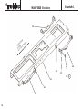
Baustufe 4: Montage Karosserie- und
Motorhalter
Pos.-Nr. Bezeichnung Maße (mm) Anzahl
4.1 Karosseriehalter 2
4.2 Blechschraube ø 2,2 x 6,5 8
4.3 Sechskantmutter M 2,5 4
4.4 Gewindestange M 2,5 x 45 2
4.5 Motorhalter 1
Montage Karosserie- und Motorhalter (Pos. 4.1 - 4.5)
- Karosseriehalter 4.1 mit Blechschrauben 4.2 am
Leiterrahmen 1.1 verschrauben.
- Je eine Sechskantmutter 4.3 auf die Gewindestangen
4.4 aufdrehen, Maß beachten!
- Einheiten 4.3 - 4.4 durch den Leiterrahmen 1.1 schie-
ben und von hinten je eine zweite Sechskantmutter 4.3
aufdrehen.
- Einheiten mit äußerer Sechskantmutter 4.3 kontern
und mit flüssigem Schraubensicherungsmittel sichern.
- Motorhalter 4.5 mit Blechschrauben 4.2 am
Leiterrahmen 1.1 verschrauben.
Stage 4: Assembling bodywork holder and
motor mount
Part No. Description Size (mm) No. off
4.1 Bodywork holder 2
4.2 Self-tapping screw ø 2,2 x 6,5 8
4.3 Hexagon nut M 2,5 4
4.4 Threaded rod M 2,5 x 45 2
4.5 Motor mount 1
Assembling bodywork holder and motor mount
(parts 4.1 - 4.5)
- Attach the bodywork holders 4.1 to the ladder frame
1.1, using the self-tapping screws 4.2
- Screw a hexagon nut 4.3 onto each of the threaded
rods 4.4, keeping to the stated dimension!
- Slip the assemblies 4.3 - 4.4 through the ladder frame
1.1. Fit two further hexagon nuts 4.3 from behind.
- Tighten the outer hexagon nuts 4.3 to lock them in
place. Secure the nuts with thread-lock fluid.
- Attach the motor mount 4.5 to the ladder frame 1.1
using the self-tapping screws 4.2
Stade 4: Montage du support-carrosserie et du
support-moteur
n° désignation cotes (mm) nbre
4.1 support-carrosserie 2
4.2 vis autotaraudeuse ø 2,2 x 6,5 8
4.3 écrou six pans M 2,5 4
4.4 tige filetée M 2,5 x 45 2
4.5 support-moteur 1
Montage du support-carrosserie et du support-moteur
(n° 4.1 - 4.5)
- Visser le support-carrosserie 4.1 avec les vis
autotaraudeuses 4.2 au châssis 1.1.
- Monter chaque fois un écrou six pans 4.3 sur les tiges
filetées 4.4. Tenir compte de la cote indiquée.
- Planter les unités 4.3 - 4.4 dans les alésages du
châssis.
- Monter chaque fois un écrou six pans 4.3 de l´arrière.
- Les bloquer avec l´écrou six pans extérieur, freiner
avec un produit approprié.
- Visser le support-moteur 4.5 avec les vis
autotaraudeuses 4.2 au châssis 1.1
MAN F2000 Evolution
Baustufe 4
15

5.6
5.5
5.1
3.9
5.3
5.11
5.2
5.4
MAN F2000 Evolution
Baustufe 5
16
5.10
5.13
5.12
5.7, 100 nF
5.7, 100 nF
5.9, 47 nF
5.8

Baustufe 5: Antrieb
Pos.-Nr. Bezeichnung Maße (mm) Anzahl
5.1 Welle mit Zahnrad, Z66 1 n.e.
5.2 Getriebegehäuse 1 n.e.
5.3 Kupplung 1
5.4 Madenschraube M3 x 3 2
5.5 Rückwand 1 n.e.
5.6 E-Motor 1 n.e.
5.7 Kondensator 100 nF 2 n.e.
5.8 Isolierschlauch 4 n.e.
5.9 Kondensator 47 nF 1 n.e.
5.10 Fahrtregler 1 n.e.
5.11 Zylinderschraube
mit Innensechskant M3 x 10 2 n.e.
5.12 Kardanwelle ø 5 x 132 1
5.13 Doppelklebeband 1 n.e.
Montage des Elektromotors und des Antriebsstrangs
(Pos. 5.1- 5.13)
- Welle mit Zahnrad 5.1 in das Getriebegehäuse 5.2
einstecken.
- Kupplung 5.3 mit Madenschrauben 5.4 am Wellenende
montieren.
- Zahnrad mit Präzisionsfett leicht einfetten und
Rückwand 5.5 einsetzen.
- Den Motor 5.6 entstören. Dazu die Kondensatoren 5.7
(100 nF) jeweils mit einem Beinchen an das Gehäuse
löten, welches dazu blankzufeilen ist. Zweites
Beinchen mit Isolierschlauch 5.8 an die Motorpole
stecken. Die Beinchen des Kondensators 5.9 (47 nF)
mit Isolierschlauch 5.8 versehen und ebenfalls an die
Motorpole stecken.
- Das Motoranschlußkabel des Reglers 5.10 an die Mo-
torpole löten, die Kondensatoren werden dabei mitver-
lötet. Auf richtige Polarität achten. Regleranleitung
beachten.
- Elektromotor 5.6 und Einheit 5.1 - 5.5 mit den
Innensechskant-Zylinderschrauben 5.11 am
Motorhalter 4.5 verschrauben, dabei die Kardanwelle
5.12 in die Kupplung 5.3 und die Antriebswelle 3.9 ein-
setzen.
- Regler 5.10 mit Doppelklebeband 5.13 am Motor 5.6
befestigen.
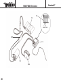
Stage 5: The power system
Part No. Description Size (mm) No. off
5.1 Shaft and gear, 66-tooth 1 N.I.
5.2 Gearbox housing 1 N.I.
5.3 Coupling 1
5.4 Grubscrew M3 x 3 2
5.5 Rear cover 1 N.I.
5.6 Electric motor 1 N.I.
5.7 Capacitor 100 nF 2 N.I.
5.8 Insulating sleeve 4 N.I.
5.9 Capacitor 47 nF 1 N.I.
5.10 Speed controller 1 N.I.
5.11 Socket-head cap screw M3 x 10 2 N.I.
5.12 Propeller shaft 5 Ø x 132 1
5.13 Double-sided foam tape 1 N.I.
Assembling and installing the electric motor and power
train (parts 5.1 - 5.13)
- Fit the shaft and gear 5.1 in the gearbox housing 5.2.
- Fit the coupling 5.3 on the end of the shaft and fit the
grubscrews 5.4.
- Lubricate the gear lightly with precision grease and fit
the rear cover 5.5.
- The next step is to attach the suppressors to the termi-
nals of the motor 5.6: file two areas of the motor can
perfectly clean close to the terminals, and solder one
pin of each 100 nF capacitor 5.7 to those points. Slip a
piece of insulating sleeve 5.8 on the other pins, and
thread the ends through the motor terminals. Insulate
both pins of the 47 nF capacitor 5.9 and slip it through
both terminals to form a bridge.
- Solder the power cables attached to the speed con-
troller 5.10 to the motor terminals, soldering the
capacitors in place at the same time. Take care to
maintain correct polarity, and read the instructions
supplied with the speed controller.
- Fix the electric motor 5.6 and the assembly 5.1 - 5.5
to the motor mount 4.5 using the socket-head cap
screws 5.11.
- At the same time slide the propeller shaft 5.12 into the
coupling 5.3 and the drive shaft 3.9.
- Fix the speed controller 5.10 to the motor 5.6 using
double-sided foam tape 5.13.
Stade 5: Montage du moteur électrique et de
l’entraînement
n° désignation cotes (mm) nbre
5.1 arbre avec roue dentée, 66 dents 1 n.c.
5.2 carter d’engrenage 1 n.c.
5.3 accouplement 1
5.4 vis sans tête M 3 x 3 2
5.5 paroi arrière 1 n.c.
5.6 moteur électrique 1 n.c.
5.7 condensateur 100 nF 2 n.c.
5.8 tube isolant 4 n.c.
5.9 condensateur 47 nF 1 n.c.
5.10 variateur 1 n.c.
5.11 vis à tête cylindrique
six pans creux M 3 x 10 2
5.12 cardan ø 5 x 132 1
5.13 adhésif double face 1 n.c.
Montage du moteur électrique et de l’entraînement
(n° 5.1 à 5.13)
- Planter l’arbre avec la roue dentée 5.1 dans le carter
d’engrenage 5.2.
- Monter l’accouplement 5.3 avec les vis sans tête 5.4
sur l’extrémité de l’arbre.
- Graisser légèrement la roue dentée avec de la graisse
de précision et mettre la paroi arrière 5.5 en place.
- Antiparasiter le moteur 5.6. Pour ce faire, souder
chaque fois une broche des condensateurs 5.7 (100
nF) au carter du moteur après en avoir poncé la sur-
face. Raccorder les autres extrémités aux pôles du
moteur en les engageant à laide d’un morceau de tube
isolant 5.8. Munir les broches du condensateur 5.9 (47
nF) de morceaux de tube isolant 5.8 et les raccorder
également aux pôles du moteur.
- Souder cordon du moteur solidaire du variateur aux
pôles du moteur en soudant simultanément les
broches des condensateurs. Veiller à observer les
polarités. Tenir compte des indications fournies
par la notice du variateur.
- Visser le moteur électrique 5.6 et l’unité 5.1 à 5.5 avec
les vis à tête cylindrique six pans creux 5.11 au sup-
port-moteur 4.5.
- Ce faisant, engager le cardan 5.12 dans l’accouple-
ment 5.3 et l’arbre d’entraînement 3.9.
- Fixer le variateur 5.10 avec de l’adhésif double face
5.13 au moteur 5.6.
MAN F2000 Evolution
Baustufe 5
17

MAN F2000 Evolution
Baustufe 6
18
1.1
6.3
6.1
6.11
4.4
6.2
6.5
6.6
6.7 6.8
4.4
6.5 - 6.9
6.10
R
rechte Seite
Right-hand side
à droite
L linke Seite
Left-hand side
à gauche
Rand schwarz lackieren
paint the edge black
peindre le bord en noir
6.12
6.9
6.11
6.4
L
6.12
6.3 (L)
6.3 (R)
6.3
6.4
6.5 - 6.9
6.10
L
L
R
R

MAN F2000 Evolution
Baustufe 6
19
Baustufe 6: Kotflügel und Rückleuchten
Pos.-Nr. Bezeichnung Maße (mm) Anzahl
6.1 Kotflügel, vorne rechts 1
6.2 Kotflügel, vorne links 1
6.3 Kotflügel, hinten, zweiteilig 2
6.4 Zylinderschraube M2 x 40 4
6.5 Rücklicht 2
6.6 Streuscheibe, klar-transparent 2
6.7 Streuscheibe, rot-transparent 4
6.8 Streuscheibe, orange-transparent 2
6.9 Rücklicht-Halter 2
6.10 Blechschraube ø2,2 x 9,5 4
6.11 Sechskantmutter M2 4
6.12 Schlauchstück ø 4 x 15 4
Vorbereitende Arbeiten:
- Die hinteren Kotflügel 6.3 nach den inneren
Markierungen teilen. Die Mittelteile werden nicht
benötigt.
- Kotflügel 6.1 - 6.3 und Rücklichthalter 6.9
grundieren, lackieren und trocknen lassen.
- Metallisierung der Rücklichter 6.5 an den Klebeflächen
und stirnseitig am umlaufenden Rand entfernen!
Rand schwarz lackieren.
Zusammenbau der rückwärtigen Beleuchtungseinheit
und Montage der Kotflügel (Pos. 6.1- 6.12)
- Streuscheiben 6.6 - 6.8 in die Rücklichter 6.5 einset-
zen und mit wenig Sekundenkleber sichern.
- Einheiten 6.5 - 6.8 in die Rücklicht-Halter 6.9 einkle-
ben.
- Erstellen Sie zwei spiegelbildliche Rücklicht-Einheiten,
1x Blinker rechts, 1x Blinker links.
- Rücklicht-Halter 6.9 mit Blechschrauben 6.10 an die
hinteren Kotflügel 6.3 schrauben,
- überstehende Schraubenenden kürzen.
- Vordere Kotflügel 6.1 und 6.2 auf die Gewindestangen
4.4 aufstecken.
- Zylinderschrauben 6.4 mit Sechskantmuttern 6.11 am
Leiterrahmen 1.1 verschrauben, mit flüssigem
Schraubensicherungsmittel sichern.
- Schlauchstücke 6.12 aufschieben.
- Kotflügel 6.3 mit dem längeren Schenkel nach vorne
auf die Schraubenenden aufschieben und ausrichten
(Abstand zum Chassis 6mm) und mit wenig
Sekundenkleber fixieren.
Stage 6: Mudguards and rear light clusters
Part No. Description Size (mm) No. off
6.1 Front right-hand mudguard 1
6.2 Front left-hand mudguard 1
6.3 Rear mudguard, two parts 2
6.4 Socket-head cap screw M2 x 40 4
6.5 Rear light cluster 2
6.6 Light cover, clear 2
6.7 Light cover, red translucent 4
6.8 Light cover, orange translucent 2
6.9 Rear light holder 2
6.10 Self-tapping screw 2.2 Ø x 9.5 4
6.11 Hexagon nut M2 4
6.12 Hose ø 4 x 15 4
Preparation:
- Cut the rear mudgards 6.3 in two pieces along the lines
shown on the inner side. The centre parts are not nee-
ded.
- Prime the mudguards 6.1 - 6.3 and the rear light holder
6.9, paint them and allow to dry.
- Remove metallised coating from joint surface and front
face of the rear lights 6.5. Paint the edge black.
Assembling the rear light units,
installing the mudguards (parts 6.1 - 6.12)
- Push the covers 6.6 - 6.8 into the rear light clusters 6.5
and secure them with a little cyano.
- Glue the rear lights 6.5 - 6.8 in the rear light holders 6.9.
- Take care to make up two mirror-image rear light
clusters, 1 x flasher right, 1 x flasher left.
- Fix the rear light holders 6.9 to the rear mudguards
6.3 using the self-tapping screws 6.10,
- cut off the excess screw length
- Slip the front mudguards 6.1 and 6.2 onto the threaded
rods 4.4.
- Screw the socket-head cap screw 6.4 into the ladder
frame 1.1. Screw a hexagon nut 6.11 onto each of the
socket-head cap screws 6.4.
Secure them with thread-lock fluid.
- Slip the pieces of hose 6.12 onto the socket-head cap
screws 6.4.
- Slip the mudguards 6.3 onto the socket-head cap
screws and align them (distance to chassis 6mm). The
longer part of the rear mudguards should face forward.
Secure the mudguards with a little cyano.
Stade 6: garde boues et feux arrière
n° désignation cotes (mm) nbre
6.1 garde boue avant droite 1
6.2 garde boue avant gauche 1
6.3 garde boue arrière, deux pièces 2
6.4 vis à tête cylindrique M2 x 40 4
6.5 feu arrière 2
6.6 diffuseur, transparent 2
6.7 diffuseur, rouge transparent 4
6.8 diffuseur, orange transparent 2
6.9 support de feu arrière 2
6.10 vis autotaraudeuse ø 2,2 x 9.5 4
6.11 écrou six pans M2 4
6.12 Flexible ø 4 x 15 4
Travaux préliminaires:
- Couper les garde-boues arrière 6.3 en deux pièces selon
les répères à l’intérieur. Les pièces médianes sont super-
flues.
- Apprêter les garde boues 6.1 à 6.3 et le support de feu
arrière 6.9, les peindre et les laisser sécher.
- Retirer le film métallisé des feux arrière 6.5 au niveau
des surfaces d´encollage et sur les parties frontales, tout
autour. Peindre le bord en noir.
Assemblage de l’unité d’éclairage arrière et
montage des garde boues (n° 6.1 à 6.12)
- Installer les diffuseurs 6.6 à 6.8 dans les feux arrière 6.5
et les fixer avec un peu de colle cyanoacrylate
- Coller les unités 6.5 à 6.8 dans les supports de feu
arrière 6.9.
- Réaliser deux unités de feux arrière symétriques,
1 clignotant à droite, 1 clignotant à gauche
- Visser le support de feu arrière 6.9 sur le garde boue
6.3 avec les vis autotaraudeuses 6.10
- couper les extrémités en saillie des vis.
- Planter les garde boues 6.1 et 6.2 sur les tiges filetées
4.4. Engager les vis à tête cylindrique 6.4 dans les alésa-
ges du châssis 1.1. Monter chaque fois un écrou six pans
6.11 et, freiner avec un produit approprié.
- Glisser les morceaux de flexible 6.12 sur le vis à tête
cylindrique.
- Planter les garde boues 6.3 sur les vis à tête cylindrique
6.4 (les languettes les plus longues sont tournées vers
l’avant) et les aligner par rapport aux pneumatiques
(écart par rapport au châssis 6mm). Fixer les garde
boues avec un peu de colle cyanoacrylate.

MAN F2000 Evolution
Baustufe 7
20
5.6
2.19
7.1
7.1
7.2
2.19
5.10
5.10

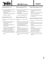
Baustufe 7: Funktionsprobe der RC-Einbauteile
(erforderliches Zubehör,
nicht im Lieferumfang)
Pos.-Nr. Bezeichnung Maße (mm) Anzahl
7.1 Empfänger 1 n. e.
7.2 Fahrakku 6V 1 n. e.
HINWEIS:
Der Einbau der RC-Komponenten erfolgt erst in den
Baustufen 11 und 12!
Anschließen des Empfängers (Pos. 7.1, 7.2)
- Lenkservo 2.19 und Fahrtregler 5.10 am Empfänger
7.1 anschließen.
- Sender einschalten.
- Steuerhebel und Trimmhebel der Fernsteueranlage
in Neutralstellung bringen ( siehe Anleitung
Fernsteueranlage).
- Geladenen Fahrakku 7.2 am Fahrtregler anschließen.
- Den Fahrtregler gemäß separater Anleitung
einstellen.
Funktionsprobe der RC-Komponenten
- Fahrzeug unterbauen, sodaß die Räder frei drehen
können und der volle Lenkausschlag möglich ist.
- Neutralstellung und Lenkeinschlag bzw.
Neutralstellung und Drehrichtung der Hinterräder
entsprechend der Position der Steuerhebel am Sender
prüfen:
Bei entgegengesetztem Lenkeinschlag:
Servo-Reverse am Sender betätigen.
Bei nicht korrekter Neutralstellung der Lenkung:
Eingestellte Längen des Lenkgestänges 2.26 und der
Spurstange 2.25 nachjustieren.
Bei falscher Drehrichtung der Hinterräder:
Motor-Anschlußkabel vertauschen.
- Verbindung Akku - Regler trennen.
Stage 7: Checking the RC system
(essential accessories,
not included in the kit)
Part No. Description Size (mm) No. off
7.1 Receiver 1 N.I.
7.2 6 V drive battery 1 N.I.
NOTE:
The RC units are installed permanently in the Stages 11
and 12.
Connecting the receiver (parts 7.1, 7.2)
- Connect the steering servo 2.19 and the speed control
ler 5.10 to the receiver 7.1.
- Switch on the transmitter.
- Set the transmitter sticks and trims to the neutral
position (see instructions supplied with the RC-system)
- Charge up the drive batterie 7.2 and connect it to
the speed controller.
- Adjust the speed controller as described in
the instructions supplied with it. Please see the
separate sheet for details of the recommended RC
equipment.
Checking the operation of the RC system
- Chock up the vehicle in such a way that the wheels
can rotate freely, and the steered wheels can move to
their full travel.
- Check the steering neutral position and travel in both
directions. Check the neutral position and direction of
rotation of the rear wheels when you move the
transmitter sticks.
If the steering system works the wrong way round:
Operate the servo reverse facility on your transmitter.
If the neutral position of the steering system is not cor-
rect:
Adjust the length of the steering pushrod 2.26 and the
trackrod 2.25.
If the rear wheels rotate in the wrong direction:
Swap over the power cables at the motor terminals.
- Disconnect the drive battery.
Stade 7: essai de fonctionnement des éléments
de l’ensemble de réception
(accessoires nécessaires non contenus
dans la boîte de construction)
n° désignation cotes (mm) nbre
7.1 récepteur 1 n.c.
7.2 accu 6 volts de propulsion 1 n.c.
À NOTER:
la mise en place des composants de l’ensemble de
réception n’interviendra qu’aux stades 11 et 12!
Raccordement de l’émetteur (n° 7.1 à 7.2)
- Raccorder le servo de direction 2.19 et le variateur de
vitesse 5.10 au récepteur 7.1.
- Mettre l’émetteur en marche.
- Amener les palonniers et les trims au neutre sur
l’émetteur (cf. les indications ci-joint).
- Raccorder l’accu du moteur 7.2 au variateur de vitesse.
- Régler le variateur en fonction des indications de la
notice qui l’accompagne.
Essai de fonctionnement des éléments de l’ensemble de
radiocommande
- Installer le véhicule sur des cales de sorte que les roues
puissent tourner librement et qu’il soit possible de
braquer complètement la direction.
- Contrôler le neutre et le débattement des roues avant et
le neutre et le sens de rotation des roues arrière en
fonction de la position des manches sur l’émetteur:
lorsque les débattements de la direction sont inversés:
intervertir au niveau du dispositif d’inversion de la
course des servos sur l’émetteur.
Si le neutre de la direction n’est pas correct:
ajuster au niveau de la longueur de la tringle de
direction 2.26 et de la barre d’accouplement 2.25.
Lorsque les roues arrière tournent dans le mauvais sens:
intervertir les brins du cordon de connexion du moteur.
- Désolidariser la liaison entre l’accu et le variateur.
MAN F2000 Evolution
Baustufe 7
21

MAN F2000 Evolution
Baustufe 8
22
8.1
8.2
8.4
8.7
8.8
8.9
8.10
8.3
8.5
8.6
8.10
1.1

Baustufe 8: Anbauteile am Chassis
Pos.-Nr. Bezeichnung Maße (mm) Anzahl
„S“ Schablone 1
8.1 Distanzstück 1
8.2 Blechschraube ø 2,2 x 6,5 2
8.3 Winkel rechts 1
8.4 Winkel links 1
8.5 Zylinderschraube M2 x 8 2
8.6 Stopmutter M2 2
8.7 Ersatzreifen 1
8.8 Ersatzfelge 1
8.9 Batteriekasten 1
8.10 Blechschraube ø 2,2 x 6,5 6
8.11 Stift ø 1,5 x 10 4
8.12 Druckluftbehälter 2
8.13 Auspuff 1
8.14 Stoßstange 1
8.15 Einstieg, rechts 1
8.16 Einstieg, links 1
8.17 Trittbrett, rechts oben 1
8.18 Trittbrett, rechts mittig 1
8.19 Trittbrett, rechts unten 1
8.20 Trittbrett, links oben 1
8.21 Trittbrett, links mittig 1
8.22 Trittbrett, links unten 1
8.23 Scheinwerfergehäuse 2
8.24 Streuscheibe, klar 19 x 9 2
8.25 Streuscheibe, orange 10 x 9 2
8.26 Streuscheibe, klar 17 x 7,5 2
8.27 U-Scheibe ø 3,2 innen 2
8.28 Zylinderschraube M2,5 x 12 2
8.29 Sechskantmutter M2,5 2
Vorbereitende Arbeiten
- Auspuff 8.13, Trittbretter 8.17 - 8.22 grundieren,
lackieren und trocknen lassen.
- Einstiege 8.15 und 8.16 mit Hilfe der Schablone „S“ auf
Seite 43 an der Stoßstange 8.14 verkleben.
- Scheinwerfergehäuse 8.23 und Streuscheiben 8.26
probeweise in die Stoßstange 8.14 einsetzen, ggf.
anpassen.
- Metallisierung der Klebeflächen am
Scheinwerfergehäuse 8.23 und stirnseitig am umlaufen-
den Rand entfernen.
Rand schwarz oder in Wagenfarbe lackieren. Einheit
8.14 - 8.16 grundieren, lackieren und trocknen lassen.
Montage der Anbauteile (Pos. 8.1 - 8.10)
- Distanzstück 8.1 mit Blechschrauben 8.2 am
Leiterrahmen 1.1 befestigen.
- Winkel 8.3 und 8.4 mit Zylinderschrauben 8.5 und
Stopmutter 8.6 noch schwenkbar verschrauben
- Ersatzreifen 8.7 auf Ersatzfelge 8.8 aufziehen.
- Ersatzrad und Batteriekasten 8.9 mit 4 Blechschrauben
8.10 befestigen.
Stage 8: External chassis fittings
Part No. Description Size (mm) No. off
„S“ Template 1
8.1 Spacer 1
8.2 Self-tapping screw 2.2 Ø x 6.5 2
8.3 Bracket, right 1
8.4 Bracket, left 1
8.5 Cheesehead screw M2 x 8 2
8.6 Self-locking nut M2 2
8.7 Spare tyre 1
8.8 Spare wheel 1
8.9 Battery box 1
8.10 Self-tapping screw 2.2 Ø x 6.5 6
8.11 Pin 1.5 Ø x 10 4
8.12 Compressed air tank 2
8.13 Exhaust 1
8.14 Bumper 1
8.15 R.H. step housing 1
8.16 L.H. step housing 1
8.17 Right-hand top step 1
8.18 Right-hand centre step 1
8.19 Right-hand bottom step 1
8.20 Left-hand top step 1
8.21 Left-hand centre step 1
8.22 Left-hand bottom step 1
8.23 Headlight housing 2
8.24 Light cover, clear 19 x 9 2
8.25 Light cover, orange 10 x 9 2
8.26 Light cover, clear 17 x 7,5 2
8.27 Washer 3.2 I.D. 2
8.28 Cheesehead screw M2,5 x 12 2
8.29 Hexagon nut M2,5 2
Preparation
- Prime the exhaust 8.13 and the steps 8.17 - 8.22,
paint them and allow to dry.
- Glue the step housings 8.15 and 8.16 to the bumper
8.14 using the template „S“, page 43, to fit.
- Trial-fit the headlight housings 8.23 and the lamp len-
ses 8.26 in the bumper 8.14 and trim if necessary.
- Remove metallized coating from joint surface and front
face of the headlight housings 8.23.
Paint the edge black or the same colour of the vehicle
- Prime parts 8.14 - 8.16, paint them and allow them to
dry.
Installing the external fittings (parts 8.1 - 8.10)
- Attach the spacer 8.1 to the ladder frame 1.1 using the
self-tapping screws 8.2. Fix the brackets 8.3 and 8.4 in
place using the cheesehead screws 8.5 and self-
locking nuts 8.6; it must be free to swivel.
- Pull the spare tyre 8.7 onto the spare wheel 8.8.
- Mount the spare wheel and the battery box 8.9 on the
model using four self-tapping screws 8.10.
Stade 8: aménagement du châssis
n° désignation cotes (mm) nbre
„S“ gabarit 1
8.1 entretoise 1
8.2 vis autotaraudeuses ø 2,2 x 6,5 2
8.3 équerre droite 1
8.4 équerre gauche 1
8.5 vis à tête cylindrique M 2 x 8 2
8.6 écrou autobloquant M 2 2
8.7 roue de secours 1
8.8 jante de la roue de secours 1
8.9 boîtier d’accu 1
8.10 vis autotaraudeuses ø 2,2 x 6,5 6
8.11 goupille ø 1,5 x 10 4
8.12 réservoir d’air comprimé 2
8.13 échappement 1
8.14 pare-chocs 1
8.15 marchepied droit 1
8.16 marchepied gauche 1
8.17 marche, droite en haut 1
8.18 marche, droite au milieu 1
8.19 marche, droite en bas 1
8.20 marche, gauche en haut 1
8.21 marche, gauche au milieu 1
8.22 marche, gauche en bas 1
8.23 boîtier de projecteur, transparent 2
8.24 diffuseur transparent 19 x 9 2
8.25 diffuseur, orange 10 x 9 2
8.26 diffuseur, transparent 17 x 7,5 2
8.27 rondelle ø 3,2 intér. 2
8.28 vis à tête cylindrique M2,5 x 12 2
8.29 écrou six pans M2,5 2
Travaux préliminaires:
- Apprêter l’échappement 8.13 et les marches 8.16 à
8.22, les peindre et les laisser sécher
- Coller les marchepieds 8.15 et 8.16 au pare-chocs
8.14 selon les indications du gabarit „S“ à la page 43.
- Installer les boîtiers de projecteur 8.23 et les diffuseurs
8.26 pour essai dans le pare-chocs 8.14, si nécessai-
re, les ajuster. Retirer le film métallisé des boîtiers de
projecteur 8.23 au niveau des surfaces d´encollage et
sur les parties frontales, tout autour. Peindre le bord
en noir ou à la couleur du véhicule.
- Apprêter, peindre et laisser sécher l’unité 8.14 à 8.16.
Montage des éléments d’aménagement (n° 8.1 à 8.10)
- Fixer l’entretoise 8.1 au châssis 1.1 avec les vis
autotaraudeuses 8.2.
- Visser les équerres 8.3 et 8.4 de manière mobile avec
les vis à tête cylindrique 8.5 et les écrous autoblo-
quants 8.6. Monter le pneu de secours 8.7 sur la jante
de secours 8.8. Fixer la roue de secours et le boîtier
d’accu avec quatre vis autotaraudeuses 8.10.
MAN F2000 Evolution
Baustufe 8
23
La page est en cours de chargement...
La page est en cours de chargement...
La page est en cours de chargement...
La page est en cours de chargement...
La page est en cours de chargement...
La page est en cours de chargement...
La page est en cours de chargement...
La page est en cours de chargement...
La page est en cours de chargement...
La page est en cours de chargement...
La page est en cours de chargement...
La page est en cours de chargement...
La page est en cours de chargement...
La page est en cours de chargement...
La page est en cours de chargement...
La page est en cours de chargement...
La page est en cours de chargement...
La page est en cours de chargement...
La page est en cours de chargement...
La page est en cours de chargement...
La page est en cours de chargement...
-
 1
1
-
 2
2
-
 3
3
-
 4
4
-
 5
5
-
 6
6
-
 7
7
-
 8
8
-
 9
9
-
 10
10
-
 11
11
-
 12
12
-
 13
13
-
 14
14
-
 15
15
-
 16
16
-
 17
17
-
 18
18
-
 19
19
-
 20
20
-
 21
21
-
 22
22
-
 23
23
-
 24
24
-
 25
25
-
 26
26
-
 27
27
-
 28
28
-
 29
29
-
 30
30
-
 31
31
-
 32
32
-
 33
33
-
 34
34
-
 35
35
-
 36
36
-
 37
37
-
 38
38
-
 39
39
-
 40
40
-
 41
41
-
 42
42
-
 43
43
-
 44
44


ROBBE MAN F2000 Evolution Assembly And Operating Instructions Manual
- Catégorie
- Jouets télécommandés
- Taper
- Assembly And Operating Instructions Manual
dans d''autres langues
- English: ROBBE MAN F2000 Evolution
- Deutsch: ROBBE MAN F2000 Evolution
Documents connexes
-
ROBBE MAN F2000 lorry tractor unit Assembly And Operating Instructions Manual
-
-
-
-
-
Autres documents
-
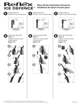 Reflex Ice Defence Winter Le manuel du propriétaire
-
laerdal BaXstrap Spineboard Mode d'emploi
-
Gerni G3H Mode d'emploi
-
Master BLP 17M DC Le manuel du propriétaire
-
Mountfield MR48Li Mode d'emploi
-
Wacker Neuson G150 Manuel utilisateur
-
-
-
Wacker Neuson G120 Manuel utilisateur
-
BCS 739 Le manuel du propriétaire
