ROBBE 3341 Assembly And Operating Instructions Manual
- Catégorie
- Jouets télécommandés
- Taper
- Assembly And Operating Instructions Manual

Montage- und Bedienungsanleitung
Assembly and operating instructions
Notice de montage et d’utilisation
Flachbettauflieger
Flatbed trailer / Remorque à plateau
No. 3341

2
Contenu de la boîte de construction
- Châssis en aluminium, fraisé sur machine à commande
numérique
- Éléments d’aménagement en aluminium noir, fraisés sur
machine à commande numérique
- Train à trois essieux avec jantes et pneus large spécial
camion
- Profilés spéciaux pour le raccordement des éléments
d’aménagement
- Éléments de décoration tels que roue de secours, feux
arrière à quatre chambres, garde-boue, etc.
- Plate-forme en plastique à profilés doubles en L et pan-
neau avant
- Plan de chargement et carénage de paroi avant en bois
de 6 mm d’épaisseur
Équipement spécial
Kit d’aménagement de l’ensemble de radiocommande,
réf. 3341 1000
Kit d’éclairage remorque, réf. 8412
Commute la plupart des fonctions d’éclairage par liaison
infrarouge à partir de la tractrice (commutable).
Kit d’ampoules pour la remorque, réf. 1681
Étais de remorque radiocommandés (dans le kit d’aménage-
ment de l’ensemble de radiocommande)
Caractéristiques techniques
Echelle de reproduction 16e
Longueur : approx. 786 mm
Largeur : approx. 158 mm
Hauteur hors tout : approx. 215 mm
Hauteur du plan de chargement : approx. 88 mm
Poids : approx. 2900 g
Recommandations générales
Accessoires indispensables, cf. feuillet joint.
Outillage et accessoires de montage, cf. catalogue général
robbe.
Recommandations générales concernant le montage
Avant d’entreprendre la construction, lire attentivement la
Inhalt des Montagekastens
- Alu-Rahmenchassis, CNC gefräst
- Schwarze Alu-Anbauteile, CNC-gefräst
- Dreiachs-Fahrgestell mit LKW-Breitreifen und -felgen
- Spezielle Profile zur Verbindung der Aufbauteile
- Anbauteile wie Ersatzrad, 4-Kammer Rückleuchten,
Schmutzfänger etc.
- Kunststoff-Plattform mit Doppel-L-Profilen und Stirnwand
- Ladefläche und Stirnwandverkleidung aus 6 mm starkem
Holz
Sonderausstattung
RC-Ausbauset, Bestell Nr. 3341 1000
Lichtset Trailer, Bestell Nr. 8412
Schaltet sämtliche Beleuchtungsfunktionen per Infrarot-
Kopplung von der Sattelzugmaschine (abschaltbar)
Glühlampenset Trailer, Bestell Nr. 1681
Fernsteuerbare Aufliegerstützen
(im RC-Ausbauset enthalten)
Technische Daten
Maßstab 1:16
Länge ca. 786 mm
Breite ca 158 mm
Höhe ü. a. ca. 215 mm
Ladeflächenhöhe ca. 88 mm
Gewicht ca. 2900 g
Allgemeine Hinweise
Erforderliches bzw. geeignetes Zubehör:
Siehe Beilageblatt
Werkzeuge und Hilfsmittel:
Siehe robbe Hauptkatalog
Allgemeine Hinweise für den Zusammenbau
Verschaffen Sie sich vor Baubeginn einen Überblick über die
Kit contents
- CNC-machined aluminium frame chassis
- CNC-machined black aluminium fittings
- Triple-axle running gear with wide truck tyres and wheels
- Special profiled rails for joining the trailer body compo-
nents
- External fittings including spare wheel, four-chamber rear
lamp clusters, mudguards etc.
- Plastic platform with channel-section rails and front panel
- 6 mm thick wooden loading platform and front panel fai-
ring
Optional accessories
RC expansion set, Order No. 3341 1000
Trailer lighting set, Order No. 8412
Controls all lighting functions via infra-red coupling from
saddle tractor unit (can be switched off)
Trailer bulb set, Order No. 1681
Working trailer strut system (included in RC expansion set)
Specification
Scale 1:16
Length approx. 786 mm
Width approx. 158 mm
Overall height approx. 215 mm
Loading platform height approx. 88 mm
Weight approx. 2900 g
General notes
Essential and recommended accessories:
See separate sheet
Tools and aids to building:
See main robbe catalogue
Assembling the model
Before you start construction, please study the stage in hand,
referring to the drawings, parts list and written instructions.
Flachbettauflieger
No. 3341

jeweilige Baustufe anhand der Zeichnungen, der Stückliste
und der Anleitungstexte.
Die Reihenfolge des Zusammenbaus ergibt sich im wesent-
lichen aus den Positionsnummern in den Zeichnungen,
Stücklisten und Anleitungstexten.
Die Nummer vor dem Punkt gibt die Baustufe, die Nummer
hinter dem Punkt gibt das betreffende Bauteil an.
Die Identifikationszeichnung für die Stanzteile finden Sie auf
Seite 23.
Richtungsangaben sind immer in Fahrtrichtung vor-
wärts, von oben zu sehen!
Sichern Sie alle Metall-Metall Schraubverbindungen
mit einem flüssigen Schraubensicherungsmittel, z.
B. Loctite, insbesondere, wenn dies in der
Zeichnung vermerkt ist.
Entfetten Sie Schrauben und Gewinde vor dem Aufbringen
der Schraubensicherung!
Empfohlene Klebstoffe:
Sekundenkleber (Einkomponentenkleber)
Stabilit-Express
oder Doppelklebeband
Zu verklebende Teile müssen frei von Lack sein!
Lackierung:
Vor dem Lackieren sollten Sie die Teile probeweise montie-
ren und ggf. anpassen. Lackierung vor der endgültigen
Montage bzw. dem Verkleben der Teile vornehmen.
Entfetten Sie die zu lackierenden Teile vor dem Lackieren mit
Alkohol oder Spiritus.
Grundieren Sie die zu lackierenden Teile.
Verwenden Sie Acryl- oder Kunstharzlacke.
Die beiden Holzplatten beidseitig lackieren, um Verzüge zu
vermeiden.
In general terms the sequence of assembly follows the part
numbers as shown in the drawings, the parts lists and the
instructions.
The number before the point indicates the Stage of con-
struction, the number after the point the individual compo-
nent.
Directions are always as seen from the top rear of the
model looking forward.
The identification drawing for the trailer parts is printed on
page 23.
All metal-metal screwed joints should be secured
with thread-lock fluid, e.g. Loctite (L). This is particu-
larly important when stated in the drawing.
De-grease screws and other threaded parts before applying
thread-lock fluid.
Adhesives:
Cyano (one-shot cyano-acrylate glue)
Stabilit-Express
or double-sided tape
Apply glue only to unpainted surfaces.
Painting:
Trial-fit all parts and trim where necessary before painting. It
is always best to paint individual parts or sub-assemblies
before finally gluing or screwing them to the model.
Remove all traces of grease from parts to be painted using
meths or white spirit.
All parts should be given a coat of primer before the final
colour finish.
Use only acrylic-based or synthetic enamel paints.
The two wooden components should be painted on both
sides, otherwise they could warp.
Flachbettauflieger
No. 3341
3
ACHTUNG! Wir empfehlen, die Bauanleitung für spätere Wartungs- und Demontagearbeiten aufzuheben!
CAUTION: We recommend that you store the building instructions carefully in case you need to dismantle the model for maintenance.
IMPORTANT! Conservez ce notice de montage et d´utilisation pour toutes les réparations ultérieures!
!
notice au regard des listes de pièces et des schémas.
La séquence d’assemblage est indiquée principalement par
les numéros de position des schémas, les listes de pièces et
les textes de construction.
Le numéro précédant le point correspond au stade de mon-
tage en cours alors que le numéro suivant le point corre-
spond à la pièce elle-même.
Le schéma d’identification des pièces estampées figure à la
page 23.
Les données directionnelles sont à voir dans le sens de
déplacement du véhicule.
Bloquer tous les vissages assurés par des vis métal-
liques avec du Loctite ou un produit équivalent, parti-
culièrement lorsque cela est mentionné par la notice
de construction.
Dégraisser le filetage et les vis avant d’appliquer le frein.
Colles recommandées
Colle cyanoacrylate (monocomposant)
Stabilit-Express ou double face.
Les éléments à coller doivent être exempts de peinture.
Mise en peinture :
Avant de peindre, monter ou ajuster les pièces. Puis les
déposer pour les peindre avant leur mise en place définitive.
Dégraisser les éléments à peindre avec de l’alcool ou de l’ét-
hanol.
Apprêter les pièces avant d’appliquer la peinture.
Utiliser des peintures acryliques ou à base de résine syn-
thétique.
Peindre les deux montants de bois latéraux pour éviter leur
gauchissement.
!
L
L
L

Flachbettauflieger
Baustufe 1
4
1.2
1.5
1.1
1.3
1.4
1.6
1.7
1.8
II
I
III
IV
1.1
1.3
1.2
1.4
1.5
1.61.5
1.2
1.1
1.1
1.1
1.3
1.2
1.4
1.5
1.5
1.2
1.6
1.8
1.1
1.3
1.2
1.5
1.6
1.7

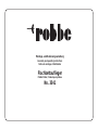
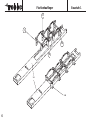
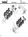
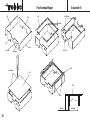
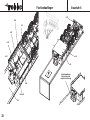
Baustufe 1: Montage der Blattfederhalterungen I – IV
Nr. Bezeichnung Material, Maße in mm Anzahl
1.1 Stoppmutter M3 12
1.2 U-Scheibe ø 3,2 x ø 9 x 0,8 12
1.3 Gewindestange M3 x 80 4
1.4 Blattfeder Stahl 6
1.5 Blattfederhalter Ku-Spritzteil 12
1.6 Achshalter Ku-Spritzteil 8
1.7 Distanzrohr ø 3,2 x ø 4 x 46 2
1.8 Distanzrohr ø 3,2 x ø 4 x 22,5 2
1.9 Leiterrahmen Alurohr 1
1.10 Blechschraube ø 2,2 x 6,5 16
- Die vier verschiedenen Blattfederhalterungen I - IV wie in
den Abbildungen zu sehen zusammenbauen. Die
Numerierung der Teile gibt die Reihenfolge des
Zusammenbaus vor.
- Die Achsen sind symmetrisch aufgebaut. Spiegelbildliche
Lage der Teile 1.6 beachten.
- Erst je eine Stoppmutter 1.1 auf die Gewindestangen1.3
schrauben und nach und nach die einzelnen
Komponenten montieren. Die Stoppmuttern noch nicht
fest anziehen.
- Beachten: Bei den Blattfederhalterungen I und IV das
Distanzrohr 1.7, bei den Halterungen II und III das
Distanzrohr 1.8 verwenden.
Stage 1: assembling the leaf spring supports I - IV
No. Description Material, size in mm No. off
1.1 Self-locking nut M3 12
1.2 Washer 3.2 Ø x 9 Ø x 0.8 12
1.3 Threaded rod M3 x 80 4
1.4 Leaf spring Steel 6
1.5 Leaf spring holder Inj. moulded plastic 12
1.6 Axle holder Inj. moulded plastic 6
1.7 Spacer sleeve 4 Ø x 3.2 Ø x 46 2
1.8 Spacer sleeve 4 Ø x 3.2 Ø x 22.5 2
1.9 Ladder frame Aluminium tube 1
1.10 Self-tapping screw 2.2 Ø x 6.5 16
- Assemble the four separate leaf spring supports I - IV as
shown in the drawings; the parts are assembled following
the sequence of the part numbers.
- The axles are of symmetrical construction. Note the mir-
ror-image orientation of parts 1.6.
- First fit a self-locking nut 1.1 on the threaded rod 1.3, and
slip the remaining components on the threaded rod
keeping strictly to the order shown. Don’t tighten the self-
locking nuts at this stage.
- Note: don’t forget the spacer sleeves 1.7 on leaf spring
supports I and IV, and the spacer sleeves 1.8 on supports
II and III.
Stade 1, montage des supports des ressorts à lames
I – IV
N° désignation matière, cotes nbre
1.1 écrou autobloquants M3 12
1.2 rondelle Ø 3,2 x Ø 0,9 x 0,8 12
1.3 tige filetée M3 x 80 4
1.4 ressort à lames acier 6
1.5 porte-ressort plastique injecté 12
1.6 porte-essieu plast. injecté 8
1.7 tube entretoise Ø 3,2 x Ø 4 x 46 2
1.8 tube entretoise Ø 3,2 x Ø 4 x 22,5 2
1.9 châssis alu tubulaire 1
1.10 vis autotaraudeuses Ø 2,2 x 6,5 16
- Assembler les quatre porte-ressort I – IV comme indiqué
sur les schémas. La numérotation des pièces correspond
à leur séquence d’assemblage.
- Les essieux sont symétriques. Tenir compte de la sym-
étrique des pièces 1.6.
- Installer d’abord l’écrou autobloquant 1.1 sur les tiges
filetées 1.3 et monter ensuite successivement les compo-
sants. Ne pas serrer les écrous autobloquants pour l’in-
stant.
- Attention : sur les porte-ressort I et IV, utiliser le tube
entretoise 1.7 et sur les porte-ressort II et III le tube entre-
toise 1.8.
Flachbettauflieger
Baustufe 1
5

6
Flachbettauflieger
Baustufe 1
I
II
III
IV
1.9
1.10

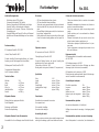
- Fit the individual leaf spring supports on the ladder frame
1.9, engage the leaf springs, and attach the supports
using the self-tapping screws 1.10.
- Tighten the self-locking nuts fully.
- Planter les porte-ressort sur le châssis 1.9, accrocher les
ressorts à lames et fixer les supports avec les vis auto-
taraudeuses 1.10.
- Serrer les écrous autobloquants.
Flachbettauflieger
Baustufe 1
7
- Die einzelnen Blattfederhalterungen auf den
Leiterrahmen 1.9 stecken, Blattfedern einhängen und
Halterungen mit Blechschrauben 1.10 befestigen.
- Stoppmuttern festziehen.

Flachbettauflieger
Baustufe 2
8
2.2
2.3
2.4
2.5
2.6
2.9
2.8
2.7
2.1
2.10
2.11
2.12
2.12
2.13
1.4
L
„X“
„X“

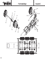
Baustufe 2: Montage der Achsen
Nr. Bezeichnung Material, Maße in mm Anzahl
2.1 Gleitlager ø 4 x ø 9 x 4 12
2.2 Felgenadapter Ku-Spritzteil 6
2.3 Reifen Gummi 6
2.4 Felge Ku-Spritzteil 6
2.5 Sechskantschraube M1,6 x 8 60
2.6 Achse ø 6 x 132 3
2.7 U-Scheibe ø 4,3 x ø 9 x 0,8 6
2.8 Stoppmutter M4 6
2.9 Radkappe Ku-Spritzteil 6
2.10 Zylinderschraube M3 x 16 12
2.11 Blattfeder Stahl 6
2.12 Achsaufnahme Ku-Spritzteil 12
2.13 Sechskantmutter M3 12
- Zwei Gleitlager 2.1 pro Felgenadapter 2.2 nach
Zeichnung eindrücken.
- Die Reifen 2.3 auf die Felgen 2.4 aufziehen und mit
etwas Sekundenkleber sichern. Anschließend die Räder
mit jeweils zehn Sechskantschrauben 2.5 an den
Felgenadaptern montieren. Vor Anziehen der
Sechskantschrauben die Radkappen 2.9 zum Zentrieren
in den Felgenadapter stecken.
- Felgenadapter mit Rad auf die Achse 2.6 aufschieben,
eine U-Scheibe 2.7 auffädeln und anschließend alles mit
einer Stoppmutter 2.8 sichern – die Stoppmutter sollte
jedoch nur soweit angezogen werden, daß sich die Räder
noch frei drehen können.
- Abschließend auf jedes Rad eine Radkappe 2.9 auf-
stecken.
- Achsen 2.6 mit Zylinderschrauben 2.10, Blattfedern 2.11,
Achsaufnahmen 2.12 und Sechskantmuttern 2.13 an den
Blattfedern 1.4 befestigen.
- Gemäß Unteransicht die Achsen so verschieben, daß sie
mittig zum Leiterrahmen ausgerichtet sind. Die Räder
müssen zueinander fluchten.
Stage 2: assembling and installing the axles
No. Description Material, size in mm No. off
2.1 Plain bush 4 Ø x 9 Ø x 4 12
2.2 Wheel driver Inj. moulded plastic 6
2.3 Tyre Rubber 6
2.4 Wheel Inj. moulded plastic 6
2.5 Hex-head screw M1.6 x 8 60
2.6 Axle 6 Ø x 132 3
2.7 Washer 4.3 Ø x 9 Ø x 0.8 6
2.8 Self-locking nut M4 6
2.9 Wheel cap Inj. moulded plastic 6
2.10 Cheesehead screw M3 x 16 12
2.11 Leaf spring Steel 6
2.12 Axle support Inj. moulded plastic 12
2.13 Hex-head nut M3 12
- Press two plain bushes 2.1 into each wheel driver 2.2
- Pull the tyres 2.3 onto the wheels 2.4 and secure them
with a few drops of cyano. Fix the wheels to the wheel
drivers using ten hex-head screws 2.5 on each one.
Before tightening the hex-head screws, temporarily fit the
hub caps 2.9 into the wheel drivers to centre them accu-
rately.
- Fit the wheel / wheel driver assemblies on the axles 2.6.
Add a washer 2.7 after each wheel, then fit the self-
locking nut 2.8 to secure it. Tighten the nuts just to the
point where the wheels still revolve freely, but without
slop.
- Press a hub cap 2.9 into each wheel.
- Attach the axles 2.6 to the leaf springs 1.4 using the
cheesehead screws 2.10, the leaf springs 2.11, the axle
supports 2.12 and the hex-head nuts 2.13.
- Adjust the position of the axles as shown in the undersi-
de view; they must be central relative to the ladder frame,
and the wheels must line up exactly with each other.
Stade 2, montage des essieux
N° désignation matière, cotes nbre
2.1 palier lisse Ø 4 x Ø 9 x 4 12
2.2 adaptateur de jante plastique injecté 6
2.3 pneus caoutchouc 6
2.4 jante plastique injecté 6
2.5 vis six pans M 1,6 x 8 60
2.6 essieu Ø 6 x 132 3
2.7 rondelle Ø 4,3 x Ø 9 x 0,8 6
2.8 écrou autobloquants M 4 6
2.9 enjoliveur plastique injecté 6
2.10 vis cylindrique M 3 x 16 12
2.11 ressort à lame acier 6
2.12 logement d’essieu plastique injecté 12
2.13 écrou six pans M 3 12
- Selon les indications du schéma, engager deux paliers
lisses 2.1 par adaptateur de jante 2.2.
- Enfiler les pneus 2.3 sur les jantes 2.4 et les y fixer un un
peu de colle cyanoacrylate. Monter ensuite les roues
avec chaque fois dix vis six pans 2.5 sur les adaptateurs
de jantes. Avant de serrer les vis six pans, planter les
enjoliveurs 2.9 sur les adaptateurs de jante afin d’obtenir
un centrage.
- Planter les adaptateurs de jante avec roue sur l’essieux
2.6, y engager une rondelle 2.7 et fixer l’ensemble avec
un écrou autobloquant 2.8 – ne serrer toutefois l’écrou de
maniére que la roue conserve sa mobilité.
- Planter ensuite les enjoliveurs sur l’ensemble des roues.
- Fixer les essieux 2.6 avec les vis cylindriques 2.10, les
ressorts à lames 2.11, les logements d’essieu 2.12 et les
écrous six pans 2.13 aux ressorts à lames 1.4.
- Selon les indications de la vue du dessous, décaler les
essieux de telle sorte qu’ils soient centrés sur le châssis.
Les roues doivent être parfaitement en ligne mutuelle-
ment
Flachbettauflieger
Baustufe 2
9

Flachbettauflieger
Baustufe 3
10
3.3
3.4
3.5
3.1
3.2
3.6
3.7
3.3
3.10
3.12
3.13
3.13
3.11
L
3.7
3.8
3.9
3.4
1.9

Baustufe 3: Montage von Stoßstange und
Aufliegerstütze
Nr. Bezeichnung Material, Maße in mm Anzahl
3.1 Stoßstangenhalter 10 x 10 x 50 1
rechts
3.2 Stoßstangenhalter 10 x 10 x 50 1
links
3.3 Blechschraube ø 2,2 x 4,5 8
3.4 Stoßstange 8 x 20 x 150 1
3.5 Zylinderschraube M2 x 6 2
3.6 Sechskantmutter M2 2
3.7 Rücklicht Ku-Spritzteil 2
3.8 Streuscheibe,
orange Ku-Spritzteil 2
3.9 Streuscheibe, rot Ku-Spritzteil 4
3.10 Streuscheibe, klar Ku-Spritzteil 2
3.11 Stützfuß Ku-Spritzteil 2
3.12 Stützrohr 8 x 8 x 50 2
3.13 Führungsrohr 10 x 10 x 50 2
Montage der Stoßstange
- Stoßstangenhalter 3.1-3.2 mit Blechschrauben 3.3 am
Leiterrahmen 1.9 befestigen.
- Stoßstange 3.4 mit Zylinderschrauben 3.5 und
Sechskantmuttern 3.6 an den Stoßstangenhaltern 3.1-
3.2 befestigen, mit flüssigem Schraubensicherungsmittel
versehen!
- Rücklichter 3.7 mit Streuscheiben 3.8-3.10 versehen und
mit wenig Sekundenkleber sichern.
- Einheiten in die Stoßstange 3.4 einsetzen und von hinten
verkleben - Sekundenkleber.
Montage der Aufliegerstütze
- Stützfüße 3.11 in den Stützrohren 3.12 verkleben.
- Die Führungsrohre 3.13 mit weiteren Blechschrauben 3.3
am Leiterrahmen montieren.
- Einheiten in die Führungsrohre 3.13 einstecken. Hinweis:
falls eine funktionstüchtige Aufliegerstütze mit dem RC-
Ausbauset montiert werden soll, Baustufe 6 beachten.
Die Rohre bitte nicht mit Sekundenkleber sichern!
- Sonst Rohre voll einschieben und mit wenig
Sekundenkleber versehen.
Stage 3: installing the bumper and trailer struts
No. Description Material, size in mm No. off
3.1 R.H. bumper holder 10 x 10 x 50 1
3.2 L.H. bumper holder 10 x 10 x 50 1
3.3 Self-tapping screw 2.2 Ø x 4.5 8
3.4 Bumper 8 x 20 x 150 1
3.5 Cheesehead screw M2 x 6 2
3.6 Hex-head nut M2 2
3.7 Rear light unit Inj. moulded plastic 2
3.8 Orange lamp lens Inj. moulded plastic 2
3.9 Red lamp lens Inj. moulded plastic 4
3.10 Clear lamp lens Inj. moulded plastic 2
3.11 Strut base Inj. moulded plastic 2
3.12 Strut tube 8 x 8 x 50 2
3.13 Guide tube 10 x 10 x 50 2
Installing the bumper
- Attach the bumper holders 3.1 / 3.2 to the ladder frame
1.9 using the self-tapping screws 3.3.
- Fix the bumper 3.4 to the bumper holders 3.1 / 3.2 using
the cheesehead screws 3.5 and hex-head nuts 3.6; apply
thread-lock fluid to secure the nuts permanently.
- Press the lamp lenses 3.8 - 3.10 into the rear light units
3.7, and secure them with a little cyano.
- Fit the light clusters into the bumper 3.4 and secure them
with a little cyano applied to the rear.
Installing the trailer struts
- Press the strut bases 3.11 into the strut tubes 3.12 and
glue them.
- Fix the guide tubes 3.13 to the ladder frame using the
remaining self-tapping screws 3.3.
- Insert these assemblies in the guide tubes 3.13. Note: if
you intend fitting working trailer struts using the optional
RC expansion set, please refer to Stage 6. Don’t glue the
tubes with cyano! If you are not fitting the working
system, push the tubes in as far as they will go, and fix
them in place with a little cyano.
Stade 3 montage du pare-chocs et des étais de remor-
que.
N° désignation matière, cotes nbre
3.1 support droit 10 x 10 x 50 1
du pare-chocs
3.2 support gauche 10 x 10 x 6 1
du pare-chocs
3.3 vis autotaraudeuse Ø 2,2 x 4,5 6
3.4 pare-chocs 8 x 20 x 150 1
3.5 vis cylindrique M 2 x 6 2
3.6 écrou six pans M 2 2
3.7 feu arrière plastique injecté 2
3.8 diffuseur orange plastique injecté 2
3.9 diffuseur rouge plastique injecté 4
3.10 diffuseur translucide plastique injecté 2
3.11 pied d’étai plastique injecté 2
3.12 tube d’étai 8 x 8 x 50 2
3.13 tube-guide 10 x 10 x 50 2
Montage du pare-chocs
- Fixer le porte-pare-chocs 3.1-3.2 avec les vis autotarau-
deuses 3.3 au châssis 1.9.
- Fixer le pare-chocs 3.4 avec les vis cylindriques 3.5 et les
écrous six pans 3.6 au pote-pare-chocs 3.1-3.2 après les
avoir munis d’un produit de freinage !
- Munir les feux arrière 3.7 des diffuseurs 3.8 – 3.10 et les
fixer avec un peu de colle cyanoacrylate.
- Mettre les unités en place dans le pare-chocs 3.4 et col-
ler de l’arrière – colle cyanoacrylate.
Montage des étais de remorque :
- Coller les pieds 3.11 dans les tubes d’étai 3.12.
- Monter les tubes-guides 3.13 avec d’autres vis autotar-
audeuses 3.3 dans le châssis.
- Planter les unités dans les tubes-guides 3.13. À noter : si
vous souhaitez monter des étais de remorque fonc-
tionnels à l’aide du kit d’aménagement de l’ensemble de
réception, observer le stade de montage 6. Ne pas coller
les tubes-guides avec de la colle cyanoacrylate ! Sinon,
pousser les étais entièrement à l’intérieur et bloquer avec
un peu de colle cyanoacrylate.
Flachbettauflieger
Baustufe 3
11

Flachbettauflieger
Baustufe 4
12
4.1 4.2
4.1
4.2
4.2
ø 1,5 mm
4.3
4.1
4.3
4.5
4.6
4.10
4.11
4.7
4.7
4.9
4.8
4.12
4.13
5
5
0
m
m
5
0
m
m
4.4
1
0
0
m
m
5
0
m
m
4
5
m
m

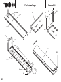
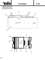
Baustufe 4: Montage des Flachbettes
Nr. Bezeichnung Material, Maße in mm Anzahl
4.1 Profil 10 x 10 x 774 2
4.2 Bodenplatte ABS, 2, Stanzteil 1
4.3 Profil 10 x 10 x 158 1
4.4 ABS-Stirnwand 2 x 136 x 151 1
4.5 Profil links 10 x 10 x 140 1
4.6 Profil rechts 10 x 10 x 140 1
4.7 Distanzstreifen 1 x 25 x 600 2
4.8 Heckblende ABS, 2, Stanzteil 1
4.9 Knotenblech ABS, 2, Stanzteil 2
4.10 Kopfblende ABS, 2, Stanzteil 1
4.11 Holz-Stirnwand 6 x 136 x 151 1
4.12 Holz-Bodenplatte 6 x 136 x 760 1
4.13 Füllplatte ABS, 2, Stanzteil 3
- In der ABS-Bodenplatte 4.2 gemäß Körnerspitzen mit
dem Handbohrer ø 1,5 mm Löcher bohren.
- Die Profile 4.1 beidseitig auf die ABS-Bodenplatte 4.2
stecken und mit Sekundenkleber verkleben. Darauf ach-
ten, daß die Profile an der Hinterkante der Bodenplatte
4.2 bündig abschließen ( ).
- Das Profil 4.3 stirnseitig mit der ABS-Bodenplatte 4.2 ver-
kleben ( ).
- Profile 4.5-4.6 auf die ABS-Stirnwand 4.4 aufstecken und
verkleben. Einheit anschließend mit Profil 4.3 verkleben,
wobei die Profile bündig abschließen müssen.
- Von den Distanzstreifen 4.7 jeweils ein 50 mm langes
Stück abschneiden. Lange und kurze Distanzstreifen laut
Zeichnung auf ABS-Bodenplatte kleben.
- Heckblende 4.8 und Knotenbleche 4.9 ans Heck der
kompletten Einheit kleben.
- Die Kopfblende 4.10 aufkleben.
- Soweit fertiggestelltes Flachbett verschleifen. Eine
Lackierung kann jetzt vorgenommen werden.
- Holz-Stirnwand 4.11 einpassen und mit den Profilen 4.5
und 4.6 mit Stabilit-Express verkleben.
- Die Bodenplatte 4.12 einpassen und mit Teilen 4.7 ver-
kleben. Die Einheit plan auflegen, um Verzüge zu ver-
meiden. Es kann wahlweise mit dünnem
Doppelklebeband oder Stabilit-Express gearbeitet wer-
den. Die ABS-Füllplatten 4.13 bündig aufeinander kleben
und zusammen mit der Holz-Bodenplatte verkleben. In
den Füllplatten kann nach Bedarf eine zusätzliche
Bordwand befestigt werden.
Stage 4: assembling the flatbed
No. Description Material, size in mm No. off
4.1 Profiled rail 10 x 10 x 774 2
4.2 Base plate ABS, 2, die-cut 1
4.3 Profiled rail 10 x 10 x 158 1
4.4 ABS front panel 2 x 136 x 151 1
4.5 L.H. profiled rail 10 x 10 x 140 1
4.6 R.H. profiled rail 10 x 10 x 140 1
4.7 Spacer strip 1 x 25 x 600 2
4.8 Rear curtain ABS, 2, die-cut 1
4.9 Gusset ABS, 2, die-cut 2
4.10 Top flange ABS, 2, die-cut 1
4.11 Wooden front panel 6 x 136 x 151 1
4.12 Wooden base plate 6 x 136 x 760 1
4.13 In-fill plate ABS, 2, die-cut 3
- Drill 1.5 mm Ø holes at the punched points in the ABS
base plate 4.2 using a hand-drill.
- Fit the profiled rails 4.1 on both sides of the ABS base
plate 4.2 and secure them with cyano. Note that the rails
must end flush with the rear edge of the base plate (4.2)
( ).
- Glue the profiled rail 4.3 to the front edge of the ABS
base plate 4.2 ( ).
- Fit the profiled rails 4.5 / 4.6 on the ABS front panel 4.4,
and glue the parts together. Glue this assembly to the
profiled rail 4.3, taking care to keep the rails flush where
they meet. Cut a piece 50 mm long from each of the spa-
cer strips 4.7. Glue the long and short spacer strips to the
ABS base plate as shown in the drawing.
- Glue the rear curtain 4.8 and the gussets 4.9 to the rear
of the flatbed assembly.
- Glue the top flange 4.10 in place as shown.
- The whole flatbed assembly should now be sanded
smooth overall before proceeding. It is a good idea to
paint the assembly at this point.
- Trim the wooden front panel 4.11 to fit and glue it to the
profiled rails 4.5 and 4.6 using Stabilit-Express.
- Trim the wooden base plate 4.12 to fit, and glue it to parts
4.7. Lay this assembly down flat on the bench before
gluing the joints, otherwise you might accidentally incor-
porate a warp. You can use either thin double-sided tape
or Stabilit-Express to fix the parts together. Glue the ABS
in-fill plates together, and glue them to the wooden base
plate in the position shown. If you wish, you can fit an
additional vertical panel using the in-fill plates as a sup-
port.
Stade 4, montage de la plate-forme
N° désignation matière, cotes nbre
4.1 profilé 10 x 10 x 774 2
4.2 plaque de fond ABS, 2, estampé 1
4.3 profilé 10 x 10 158 1
4.4 paroi frontale, ABS 2 x 136 x 151 1
4.5 profilé gauche 10 x 10 x 140 1
4.6 profilé droit 10 x 10 x 140 1
4.7 bandes entretoises 1 x 25 x 600 2
4.8 panneau arrière ABS, 2, estampé 1
4.9 gousset d’assemblage ABS, 2, estampé 2
4.10 panneau de tête ABS, 2, estampé 1
4.11 paroi frontale en bois6 x 136 x 151 1
4.12 plancher 6 x 136 x 760 1
4.13 plaque ABS, 2, estampé 3
de remplissage
- Dans la plaque de fond 4.2, selon les indications des
repères, percer des trous de Ø 1,5 mm à l’aide d’une
chignole et d’une mèche de Ø 1,5 mm.
- Planter les profilés 4.1 de chaque côté sur la plaque de
fond 4.2 et les y fixer avec de la colle cyanoacrylate.
Veiller à ce que les profilés se trouvent à fleur au niveau
de l’arrête arrière de la plaque de fond 4.2 ( ). Coller
le profilé 4.3 frontalement à la plaque de fond en ABS 4.2
( ).
- Planter les profilés 4.5-4.6 sur la paroi frontale en ABS
4.4 et coller. Coller ensuite l’unité au profilé 4.3 les pro-
filés devant se trouver à fleur.
- Couper chaque fois des morceaux de 50 mm dans la
bande-entretoise 4.7. Selon les indications du schéma,
coller chaque fois un morceau court et un morceau long
de la bande-entretoise sur la plaque de fond en ABS.
- Coller le panneau arrière 4.8 et le gousset d’assemblage
4.9 à l’arrière de l’unité complète.
- Coller le panneau de tête 4.10.
- Poncer le plateau à ce niveau là. Il est possible mainten-
ant d’appliquer la peinture.
- Ajuster le panneau frontal de bois 4.11 et le coller aux
profilés 4.5 et 4.6 avec de la colle Stabilit-Express.
- Ajuster la plaque de fond 4.12 et la coller aux éléments
4.7. Disposer l’unité à plat pour éviter son gauchisse-
ment. Il est possible de travailler au choix avec du double
face fin ou de la colle Stabilit-Express. Coller les deux
plaques de remplissage en ABS 4.13 à fleur l’une sur
l’autre avant de les coller aux plaques de bois. Dans les
plaques de remplissage il est possible, au besoin, d’ajou-
ter une paroi supplémentaire.
Flachbettauflieger
Baustufe 4
13

Flachbettauflieger
Baustufe 5
14
5.4
5.5
5.6
5.9
5.8
L
5.1
5.2
5.3
5.6
5.7
5.10
5.11
5.11 5.11
5.10
5.10
2 x
2 x
2
5
6
m
m
5.1
5.3
„D“
5.4
4.12
4.2
1.9

Stage 5: final assembly
No. Description Material, size in mm No. off
5.1 Hex-head screw M5 x 16 1
5.2 Spacer sleeve 6 Ø x 8 1
5.3 Hex-head nut M5 1
5.4 Base plate 1.5 x 50 x 50 /80 1
5.5 Countersunk 2.2 Ø x 6.5 4
s.t. screw
5.6 Self-tapping screw 2.2 Ø x 9.5 8
5.7 Wheel Inj. moulded plastic 1
5.8 Tyre Rubber 1
5.9 Self-tapping screw 2.2 Ø x 19 2
5.10 Channel-section rail 10 x 10 x 20 4
5.11 Mudguard ABS, 2, die-cut 4
- Mount the hex-head screw 5.1, spacer sleeve 5.2 and
hexagon nut 5.3 on the base plate 5.4 to suit the tractor
unit you intend to use, and secure the screw and nut with
thread-lock fluid.
- The low-profile design means that the screw 5.1 inevita-
bly stands proud. To solve this problem you can either
shorten the projecting screw end, or cut a recess in the
wooden base plate 4.12 to accept the screw - see detail
drawing „D“.
- Fix the base plate 5.2 to the ABS base plate 4.2 using the
countersunk self-tapping screws 5.5.
- Fix the ladder frame 1.9 to the ABS base plate 4.2 using
the self-tapping screws 5.6.
- Fit the tyre 5.8 on the spare wheel 5.7, secure it with a
little cyano, and fix it to the ladder frame using the self-
tapping screws 5.9.
- Glue the short pieces of channel-section rail 5.10 to the
mudguards 5.11, as shown in the drawings. Take care to
make two right-hand and two left-hand mudguards.
- Glue the mudguards to the ABS base plate.
Stade 5, finition du montage
N° désignation matière, cotes nbre
5.1 vis six pans M 5 x 16 1
5.2 tube-entretoise Ø 6 x 8 1
5.3 écrou six pans M 5 1
5.4 plaque palier 1,5 x 50 x 89 1
5.5 vis autotaraudeuses Ø 2,2 x 6,5 4
à tête fraisée
5.6 vis autotaraudeuse Ø 2,2 x 9,5 8
5.7 jante plastique injecté 1
5.8 pneu caoutchouc 1
5.9 vis autotaraudeuse Ø 2,2 x 19 2
5.10 profilé en double L 10 x 10 x 20 4
5.11 garde-boue ABS, 2, estampé 4
- En fonction de la tractrice solidaire, fixer la vis six pans
5.1 au tube-entretoise 5.2 et l’écrou six pans 5.3 sur la
plaque-palier 5.4 et bloquer avec un produit de freinage
des vis.
- À cause de la structure plane, la vis 5.1 dépasse. Soit
couper la saillie de la vis ou chanfreiner la plaque 4.12
dans le secteur de la vis – cf. schéma de détail « D ».
- Visser la plaque-palier 5.4 à la plaque de fond en ABS 4.2
avec les vis autotaraudeuses 5.5 à tête fraisée.
- Visser le châssis 1.9 à la plaque de fond en ABS 4.2 avec
les vis autotaraudeuses 5.6.
- Glisser le pneu 5.8 sur la jante 5.7 et l’y fixer avec de la
colle cyanoacrylate puis fixer la roue de secours au châs-
sis avec les vis autoataraudeuses 5.9.
- Coller chaque profilé 5.10 à un garde-boue 5.11. Tenir
compte des indications des schémas. Il faut réaliser deux
garde-boue droits et deux gauches.
- Coller les garde-boue sur la plaque de fond.
Flachbettauflieger
Baustufe 5
15
Baustufe 5: Endmontage
Nr. Bezeichnung Material, Maße in mm Anzahl
5.1 Sechskantschraube M5 x 16 1
5.2 Distanzrohr ø 6 x 8 1
5.3 Sechskantmutter M5 1
5.4 Lagerplatte 1,5 x 50 x 80 1
5.5 Senkkopf- ø 2,2 x 6,5 4
blechschraube
5.6 Blechschraube ø 2,2 x 9,5 8
5.7 Felge Ku-Spritzteil 1
5.8 Reifen Gummi 1
5.9 Blechschraube ø 2,2 x 19 2
5.10 Doppel-L-Profil 10 x 10 x 20 4
5.11 Schmutzfänger ABS, 2, Stanzteil 4
- Sechskantschraube 5.1 mit Distanzrohr 5.2 und
Sechskantmutter 5.3 an der Lagerplatte 5.4 je nach vor-
gesehener Zugmaschine befestigen und mit flüssigem
Schraubensicherungsmittel sichern!
- Bedingt durch die flache Bauweise steht die Schraube
5.1 über. Entweder überstehendes Schraubenende kür-
zen oder die Bodenplatte 4.12 im Bereich der Schraube
ausnehmen - Siehe Detailzeichnung „D“.
- Lagerplatte 5.4 mit Senkkopf-Blechschrauben 5.5 an der
ABS-Bodenplatte 4.2 verschrauben.
- Leiterrahmen 1.9 mit Blechschrauben 5.6 an ABS-
Bodenplatte 4.2 verschrauben.
- Reifen 5.8 auf Felge 5.7 schieben, mit Sekundenkleber
sichern und mit Blechschrauben 5.9 am Leiterrahmen
befestigen.
- Die einzelnen Profilstücke 5.10 jeweils mit einem
Schmutzfänger 5.11 verkleben. Die Zeichnungen beach-
ten. Es müssen je 2 rechte und linke Schmutzfänger her-
gestellt werden.
- Schmutzfänger auf ABS-Bodenplatte verkleben.

Flachbettauflieger
Baustufe 6
16
6.3
6.2
6.3
ø 8 mm
6.1
ø 5 mm
2 mm
6.4
6.1 - 6.4
6.5
ø 2,5 mm
6.6
6.7
6.7
6.8
6.8
80 mm30 mm
ø 2,5 mm

Baustufe 6: Montage RC-Ausbauset
Hinweis: Die Teile 6.1 - 6.28 sind im Montagekasten
Flachbettauflieger nicht enthalten.
Nr. Bezeichnung Material, Maße in mm Anzahl
6.1 Frontwand ABS, 2, Stanzteil 1
6.2 Rückwand ABS, 2, Stanzteil 1
6.3 Seitenwand ABS, 2, Stanzteil 2
6.4 Auflage ABS, 2, Stanzteil 1
6.5 Befestigungslasche ABS, 2, Stanzteil 4
6.6 Deckel ABS, 2, Stanzteil 1
6.7 Strebe kurz ABS, 2, Stanzteil 4
6.8 Strebe lang ABS, 2, Stanzteil 2
6.9 Blechschraube ø 2,2 x 6,5 10
6.10 Gestänge M2,5 x 30 2
6.11 Kugelkopf Ku-Spritzteil 4
6.12 Kugel mit Bund MS 2
6.13 Kugel MS 2
6.14 Sechskantmutter M2 4
6.15 Gewindestange M2 x 48 1
6.16 Gelenklasche MS 4
6.17 Schraube M2,5 x 20 4
6.18 Sechskantmutter M2,5 12
6.19 Servohebel (bei 6.23) 1
6.20 Zylinderschraube M2 x 12 1
6.21 Sechskantmutter M2 1
6.22 Akku 2
--- Doppelklebeband 2
6.23 Servo 1
6.24 Blechschraube ø 2,2 x 9,5 2
6.25 Befestigungswinkel Alu 2
6.26 Superlichtset Trailer 1
6.27 Glühlampen 8
6.28 V-Kabel AMP 1
- Die Frontwand 6.1 gemäß Körnerspitzen mit ø 5 mm und
ø 8 mm Löchern für Schalter und Ladebuchse versehen.
- Frontwand, die Rückwand 6.2 und die Seitenwände 6.3
zusammenstecken und an den Ecken mit Klebestreifen
sichern. Teile untereinander verkleben.
- Die Auflage 6.4 so einkleben, dass sich rundum ein
Abstand von 2 mm zum Rand des Kastens ergibt
- Die Befestigungslaschen 6.5 bohren und einkleben.
- Den Deckel 6.6 in den Kasten auf die Auflagen legen und
an den Körnungen mit dem Handbohrer durchbohren.
Bohrungen im Deckel auf ø 2,5 mm erweitern.
- Die kurzen Streben 6.7 mit den langen Streben 6.8 nach
Skizze zusammenkleben und am RC-Kasten verkleben.
Stage 6: installing the RC expansion set
Note: parts 6.1 to 6.26 are not included in the flatbed trai-
ler kit.
No. Description Material, size in mm No. off
6.1 Front panel ABS, 2, die-cut 1
6.2 Back panel ABS, 2, die-cut 1
6.3 Side panel ABS, 2, die-cut 2
6.4 Peripheral support ABS, 2, die-cut 1
6.5 Mounting lug ABS, 2, die-cut 4
6.6 Cover ABS, 2, die-cut 1
6.7 Short strut ABS, 2, die-cut 4
6.8 Long strut ABS, 2, die-cut 2
6.9 Self-tapping screw 2.2 Ø x 6.5 10
6.10 Pushrod M2.5 x 30 2
6.11 Ball-link Inj. moulded plastic 4
6.12 Flanged linkage ball Brass 2
6.13 Linkage ball Brass 2
6.14 Hexagon nut M2 4
6.15 Threaded rod M2 x 48 1
6.16 Actuating lever Brass 4
6.17 Screw M2.5 x 20 4
6.18 Hexagon nut M2.5 12
6.19 Servo output arm With 6.23 1
6.20 Cheesehead screw M2 x 12 1
6.21 Hexagon nut M2 1
6.22 Battery 2
- Double-sided tape 2
6.23 Servo 1
6.24 Self-tapping screw 2.2 Ø x 9.5 2
6.25 Mounting bracket Aluminium 2
6.26 Trailer super lighting set 1
6.27 Filament Bulb 8
6.28 AMP Y-lead 1
- Drill one 5 mm Ø and one 8 mm Ø hole at the punched
points in the front panel 6.1 to accept the lighting system
switch and charge socket.
- Fit together the front panel 6.1, the back panel 6.2 and
the side panels 6.3, and tape them together at the cor-
ners. Check alignment, then glue the parts together.
- Glue the peripheral support 6.4 in the box, leaving it
recessed by 2 mm all round.
- Drill 2.5 mm Ø retaining screw holes in the mounting lugs
6.5 as shown, and glue them in place.
- Place the cover 6.6 inside the box, resting on the peri-
pheral support, and drill through at the punched points
using a hand-drill. Open up the holes in the cover to 2.5
mm Ø.
Stade 6, montage du kit d’aménagement de l’ensemble
de réception.
À noter : les pièces 6.1 à 6.28 ne sont pas contenues
dans la boîte de construction de la remorque à plateau.
N° désignation matière, cotes nbre
6.1 paroi avant ABS, 2, estampé 1
6.2 paroi arrière ABS, 2, estampé 1
6.3 paroi latérale ABS, 2, estampé 2
6.4 doublure ABS, 2, estampé 1
6.5 languette de fixation ABS, 2, estampé 4
6.6 couvercle ABS, 2, estampé 1
6.7 traverse courte ABS, 2, estampé 4
6.8 traverse longue ABS, 2, estampé 2
6.9 vis autotaraudeuse Ø 2,2 x 6,5 10
6.10 tringle M 2,2 x 30 2
6.11 pivot sphérique plastique injecté 4
6.12 bille avec épaulem. laiton 2
6.13 bille laiton 2
6.14 écrou six pans M 2 4
6.15 tige filetée M 2 x 48 1
6.16 languette d’artic. laiton 4
6.17 vis M 2,5 x 20 4
6.18 écrou six pans M 2,5 12
6.19 palonnier de servo (avec 6.23) 1
6.20 vis cylindrique M 2 x 12 1
6.21 écrou six pans M 2 1
6.22 accu 2
- double face 2
6.23 servo 1
6.24 vis autotaraudeuse Ø 2,2 x 9,5 2
6.25 équerre de fixation alu 2
6.26 kit d’éclairage remorque 1
6.27 ampoules 8
6.28 cordon Y AMP 1
- Munir la paroi avant 6.1 de trous de Ø 5 et Ø 8 mm selon
les indications des repères, pour l’interrupteur et la douil-
le de charge.
- Assembler la paroi avant, la paroi arrière 6.2 et les paro-
is latérales 6.3 et les bloquer au niveau des angles à
laide de morceaux de ruban adhésif. Coller les pièces
entre elles.
- Coller la doublure 6.4 de telle manière que qu’elle pré-
sente tout autour une marge de 2 mm par rapport à la
boîte.
- Percer et coller les languettes de fixation 6.5.
Flachbettauflieger
Baustufe 6
17

Flachbettauflieger
Baustufe 6
18
6.9
6.10
6.11
6.12
6.13
6.16
6.14
6.10-6.13
6.14, 6.15
6.17
6.17
6.18
6.18
6.10
21 mm
10 mm
10 mm
6.14
6.15
L
6.20
6.21
6.19
6.10-6.13
6.14, 6.15
„D1“ „D2“ „D3“
„D4“
6.19
2 x
L
L
L
3.13
3.12

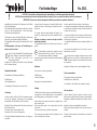
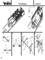
- Den RC-Kasten 6.1 - 6.8 mit vier Blechschrauben 6.9 an
der ABS-Bodenplatte festschrauben.
Bei den folgenden Arbeiten die Detailzeichnungen „D1“
- „D4“ beachten.
- Die Gestänge aus den Teilen 6.10 - 6.13 zusammenset-
zen, Maß 21 mm einstellen.
- Muttern 6.14 beidseitig auf die Gewindestange 6.15 unter
Verwendung von Loctite aufdrehen, Maß 10 mm einstel-
len.
- Die Gestänge 6.10 - 6.13 mit den Kugeln mit Bund 6.12
auf die Gewindestange schieben.
- Die Gelenklaschen 6.16 aufsetzen und mit Muttern 6.14
sichern. Loctite erst nach Funktionsprobe und Einstellung
verwenden.
- Stützrohre 3.12 und Führungsrohre 3.13 jeweils mit
Schrauben 6.17 und je zwei Muttern 6.18 versehen.
Muttern festziehen und sichern. Die Laschen 6.16 müs-
sen beweglich bleiben.
- Die Einheit 6.10 - 6.16 zwischen die Stützen setzen. Die
inneren Laschen werden dabei jeweils am Führungsrohr,
die äußeren am Stützrohr auf die Schrauben gesteckt
und mit einer Mutter 6.18 gesichert. Loctite erst nach der
Funktionsprobe verwenden.
- Den beschnittenen Servohebel 6.19 mit der
Zylinderschraube 6.20 und der Sechskantmutter 6.21
zusammen mit den Gestängen verbinden.
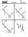
- Die Akkus 6.22 mit dünnem Doppelklebeband auf der
ABS-Bodenplatte 4.2 befestigen.
- Das Servo 6.23 mit Gummitüllen und Hülsen versehen
und mit Blechschrauben 6.24 an den Befestigungswin-
keln 6.25 festschrauben.
- Servo einsetzen und Winkel 6.25 mit Blechschrauben 6.9
am Leiterrahmen verschrauben.
- Servo mit der Fernsteuerung in die hintere Endstellung
fahren. Servohebel aufstecken.
- Die Aufliegerstütze muß jetzt eingefahren sein.
Ansonsten durch Umstecken des Servohebels auf der
Feinverzahnung des Servo-Abtriebs korrigieren.
- Hebel mit der Servohebelschraube sichern.
- Das Superlichtset-Trailer 6.26 mit Doppelklebeband auf
- Glue the short struts 6.7 to the long struts 6.8 as shown
in the sketch, and glue these assemblies to the RC box.
- Fix the RC box 6.1 - 6.8 to the ABS base plate using four
self-tapping screws 6.9.
Please refer to the detail drawings „D1“ to „D4“ for the
next procedure.
- Assemble the pushrods from parts 6.10 to 6.13, and set
them to a length of 21 mm as shown.
- Fit the nuts 6.14 on both ends of the threaded rod 6.15,
and position them 10 mm from the ends as shown.
Secure the nuts with Loctite.
- Attach the pushrods 6.10 - 6.13 to the threaded rod 6.15
by fitting the flanged linkage balls 6.12 on the rod.
- Add the actuating levers 6.16 and secure them with the
nuts 6.14. The nuts should be locked with Loctite, but
only after testing and adjusting the working trailer strut
system.
- Fit a screw 6.17 and two nuts 6.18 on each of the strut
tubes 3.12 and guide tubes 3.13. Tighten the nuts fully
and secure them. Note that the levers 6.16 must remain
free to move.
- Place the assembly 6.10 - 6.16 between the struts: fit the
inner levers on the screws attached to the guide tubes,
and the outer levers on the screws attached to the strut
tubes. Secure each one with a nut 6.18. Don’t apply the
Loctite until you have tested and adjusted the system.
- Cut down the servo output arm 6.19 to the shape shown,
and connect it to the pushrods using the cheesehead
screw 6.20 and hexagon nut 6.21.
- Attach the batteries 6.22 to the ABS base plate 4.2 using
thin double-sided tape.
- Press the rubber grommets and metal spacer sleeves
into the mounting lugs of the servo 6.23, and fix it to the
mounting brackets 6.25 using the self-tapping screws
6.24.
- Install the servo, and fix the brackets 6.25 to the ladder
frame using the self-tapping screws 6.9.
- Run the servo to the rear end-point from the transmitter,
and fit the output arm on the servo.
- The trailer strut should now be in the retracted position. If
not, remove the servo output arm and shift it to a different
position on the output shaft.
- Once you have found the correct position, fit the servo
output screw to secure the arm on the servo.
- Fix the Trailer super lighting set 6.26 on the ABS ladder
frame using double-sided tape.
- Disposer le couvercle 6.6 dans la boîte sur la doublure et
percer au niveau des repères avec une chignole. Dans le
couvercle, porter les trous à Ø 2,5 mm.
- Coller les entretoises courtes 6.7 aux entretoises longues
6.8 selon les indications du schéma puis sur la boîte de
réception.
- Visser la boîte de réception 6.1 à 6.8 avec quatre vis
autotaraudeuses 6.9 à la plaque de fond en ABS.
Pour les opérations suivantes, tenir compte des sché-
mas de détail « D1 » à « D4 ».
- Assembler la tringle à partir des pièces 6.10 à 6.13, tenir
la cote de 21 mm.
- Visser les écrous 6.14 préalablement enduits de Loctite
sur la tige filetée 6.15. Établir une cote de 10 mm.
- Glisser la tringle 6.10 à 6.13 avec les billes à épaulement
6.12 sur la tige filetée.
- Mettre les languettes d’articulation 6.16 en place et les
bloquer avec les écrous 6.14. N’appliquer de Loctite qu’a-
près avoir effectué un essai de fonctionnement et défini
les réglages
- Munir les tubes 3.12 et tubes-guides 3.13 chacun des vis
6.17 et de deux écrous 6.18. Serrer les écrous et les frei-
ner. Les languettes 6.16 doivent rester mobiles.
- Installer l’unité 6.10 à 6.16 entre les étais. Planter chaque
fois les languettes intérieures au tube-guide et les
extérieures au tube d’étai sur les vis et fixer avec un
écrou 6.18. N’appliquer le Loctite qu’après l’essai de fon-
ctionnement.
- Raccorder le palonnier de servo 6.19 coupé avec la vis
cylindrique 6.20 et l’écrou six pans 6.21 à la tringle.
- Fixer les accus 6.22 avec du double face fin sur la plaque
de fond en ABS 4.2.
- Munir le servo 6.23 des silent-blocs et des manchons et
le fixer à l’équerre 6.25 avec les vis autotaraudeuses
6.25.
- Mettre le servo en place et visser l’équerre 6.25 au châs-
sis avec les vis autotaraudeuses 6.9.
- À ‘aide de l’ensemble de radiocommande, amener le
servo dans sa fin de course arrière.
- L’étai de remorque doit alors être escamoté. Sinon, chan-
ger la position du palonnier du servo sur le crantage fin
de l’arbre de transmission du servo.
Flachbettauflieger
Baustufe 6
19

Flachbettauflieger
Baustufe 6
20
6.19-6.21
6.22
6.22
6.23
6.25
6.9
6.24
6.26
6.27
6.6
6.9
6.27
Infrarotempfänger
Infra-red receiver
récepteur infrarouge
L
4.2
La page est en cours de chargement...
La page est en cours de chargement...
La page est en cours de chargement...
La page est en cours de chargement...
-
 1
1
-
 2
2
-
 3
3
-
 4
4
-
 5
5
-
 6
6
-
 7
7
-
 8
8
-
 9
9
-
 10
10
-
 11
11
-
 12
12
-
 13
13
-
 14
14
-
 15
15
-
 16
16
-
 17
17
-
 18
18
-
 19
19
-
 20
20
-
 21
21
-
 22
22
-
 23
23
-
 24
24


ROBBE 3341 Assembly And Operating Instructions Manual
- Catégorie
- Jouets télécommandés
- Taper
- Assembly And Operating Instructions Manual
dans d''autres langues
- English: ROBBE 3341
- Deutsch: ROBBE 3341
Documents connexes
-
ROBBE MAN F2000 Evolution Assembly And Operating Instructions Manual
-
-
-
-
-
-
-
-
-
Autres documents
-
Candy CEM6822KW Manuel utilisateur
-
Candy CCG6503PW Manuel utilisateur
-
Candy CCG5540PW Le manuel du propriétaire
-
Bontrager TUBULAR WHEEL Le manuel du propriétaire
-
Castorama Kit de finition en MDF pour porte à galandage Mode d'emploi
-
Danfoss OSP Neutral Position Springs Tech Note Mode d'emploi
-
Kodak a4 Manuel utilisateur
-
 A.T.U FS4253 Manuel utilisateur
-
 MetalTech AL-K4052 Manuel utilisateur
-
ALLEGION Normbau Cavere Care 7381 Series Fixing Instructions

