Smooth Fitness 6.75 Manuel utilisateur
- Catégorie
- Tapis de course
- Taper
- Manuel utilisateur

USER’S MANUAL
675 MOTORIZED TREADMILL
USER WEIGHT LIMITATION: 350lbs(140kgs).
SERIAL NUMBER (found on frame):

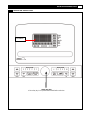
2 675i TREADMILL
PRECAUTIONS
For future service or related questions:
Please staple your receipt and/or write in the name and phone number of the retail store where you purchased your treadmill.
Name: ______________________________ Phone Number: ___________________ Receipt: ______________________
Precautions:
WARNING: To reduce the risk of burns, fire, electric shock, or injury to persons, read the following important precautions
and information before operating the treadmill. It is the responsibility of the owner to ensure that all users of this treadmill are
adequately informed of all warnings and precautions.
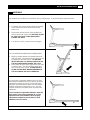
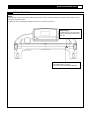
• Use the treadmill only as described in this manual.
• Place on a level surface, with 6 feet 2 X1m
of clearance behind it. Do not place the treadmill on any surface that blocks air
openings. To protect the floor or carpet from damage, place a mat under the treadmill.
• When choosing a location for the treadmill be sure that the location and position permit access to a plug.
• Keep the treadmill indoors, away from moisture and dust. Do not put the treadmill in a garage or covered patio, or near
water.
• Do not operate the treadmill where aerosol products are used or where oxygen is being administered.
• Keep children under the age of 12 and pets away from the treadmill at all times.
• The treadmill should not be used by persons weighing more than 350LBS (140 Kgs).
•
Never allow more than one person on the treadmill at a time. Wear appropriate exercise clothing when using the treadmill.
Do not wear loose clothing that could become caught in the treadmill. Athletic support clothes are recommended for both
men and women. Always wear athletic shoes. Never use the treadmill with bare feet, wearing only stockings, or in
sandals.
• When connecting the power cord, plug the power cord into a grounded circuit. No other appliance should be on the same
circuit.
• Always straddle the belt and allow it to start moving before stepping onto the belt.
• Always examine your treadmill before using to ensure all parts are in working order.
• Allow the belt to fully stop before dismounting.
• Never insert any object or body parts into any opening.
• Follow the safety information in regards to plugging in your treadmill.
• Keep the power cord away from the incline wheels and do not run the power cord underneath your treadmill. Do not
operate the treadmill with a damaged or frayed power cord.
• Always unplug the treadmill before cleaning and/or servicing. Service to your treadmill should only be performed by an
authorized service representative, unless authorized and/or instructed by the manufacturer. Failure to follow these
instructions will void the treadmill warranty.
• Never leave the treadmill unattended while it is running.
• Use “safety key” when operating the treadmill and make sure the “safety key” is clipped to the users clothing.
• Remove the “safety key” and store it in a safe place when the treadmill is not in use. Keep the “safety key” away from
children.

www.smoothfitness.com
3
PRECAUTIONS
Pour réparations futures ou questions connexes :
Please staple your receipt and/or write in the name and phone number of the retail store where you purchased your treadmill.
Name: ______________________________ Phone Number: ___________________ Receipt: ______________________
Précautions:
AVERTISSEMENT : Pour réduire les risques de brûlures, d’incendie, de choc électrique ou de blessures aux personnes, lire les
précautions importantes et l’information suivantes avant de se servir du tapis roulant. Il revient au propriétaire de s’assurer que tous
les utilisateurs de ce tapis ont bien été informés de tous les avertissements et précautions.
• Utiliser le tapis seulement comme il est décrit dans ce manuel.
• Le placer sur une surface plane, en laissant 2X1m d’espace libre en arrière. Ne pas placer le tapis roulant sur une surface
qui bloque les ouvertures d’air.
• Pour protéger le plancher ou un tapis de dommages, placer un petit tapis sous le tapis roulant.
• Choisir pour le tapis roulant un emplacement et une position qui permettent d’avoir accès à une prise murale.
• Garder le tapis roulant à l’intérieur, à un endroit sans humidité ni poussière. Ne pas mettre le tapis roulant dans un garage,
sur une terrasse couverte ou près de l’eau.
• Ne pas faire fonctionner le tapis roulant pendant la vaporisation de produits aérosol ou l’administration d’oxygène.
• Ne pas laisser les enfants de moins de 12 ans et les animaux s’approcher du tapis roulant.
• Le tapis roulant ne doit pas être utilisé par des personnes pesant plus de 160 kg (350 lb).
• Il ne doit jamais y avoir plus d’une personne sur le tapis à la fois. Porter des vêtements d’exercice appropriés pour utiliser
le tapis roulant. Ne pas porter de vêtements lâches qui pourraient être pris dans le tapis roulant. Les vêtements de soutien
athlétiques sont recommandés tant pour les hommes que pour les femmes. Porter toujours des chaussures d’athlétisme.
Ne pas être pieds nus, ou porter seulement des chaussettes ou des sandales lors de l’utilisation du tapis roulant.
• Brancher le cordon d’alimentation dans un circuit avec mise à la terre. Aucun autre appareil ne doit être sur le même
circuit.
• Toujours enjamber le tapis et le laisser commencer à rouler avant de monter dessus.
• Toujours examiner votre tapis roulant avant de l’utiliser pour s’assurer que toutes les pièces fonctionnent correctement.
• Laisser le tapis s’arrêter complètement avant de descendre.
• Ne jamais insérer d’objets ou de parties du corps dans une ouverture.
• Suivre les directives de sécurité en ce qui concerne le branchement de votre tapis roulant.
• Garder le cordon d’alimentation éloigné des roues inclinées et ne pas faire passer le cordon d’alimentation sous votre
tapis roulant. Ne pas faire fonctionner le tapis roulant si le cordon d’alimentation est endommagé ou effiloché.
• Débrancher toujours le tapis roulant avant de le nettoyer ou de le réparer.
• Toute réparation au tapis doit être effectuée par un réparateur agréé, à moins d’autorisation ou de directives contraires du
fabricant. Le non-respect de ces instructions annulera la garantie du tapis roulant.
• Ne jamais laisser le tapis roulant sans surveillance lorsque la clé de sécurité est insérée.
• Utiliser la « clé de sécurité » pour faire fonctionner le tapis roulant et s’assurer qu’elle est accrochée aux vêtements des
utilisateurs.
• Retirer la « clé de sécurité » et la ranger dans un endroit sûr lorsque le tapis roulant n’est pas en fonction. Garder la « clé
de sécurité » hors de la portée des enfants.

4 675i TREADMILL
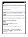
POWER REQUIREMENTS
Power Requirements:
IMPROPER CONNECTION OF THE EQUIPMENT GROUNDING CONNECTOR CAN RESULT IN THE RISK OF AN ELECTRIC
SHOCK. CHECK WITH A QUALIFIED ELECTRICIAN OR SERVICE MAN IF YOU ARE IN DOUBT AS TO WHETHER THE
PRODUCT IS PROPERLY GROUNDED. DO NOT MODIFY THE PLUG PROVIDED WITH THE PRODUCT, IF IT WILL NOT FIT
THE OUTLET; HAVE A PROPER OUTLET INSTALLED BY A QUALIFIED ELECTRICIAN.
This treadmill can be seriously damaged by sudden voltage changes in your home’s electrical power. Voltage spikes, surges and
noise interference can result from weather conditions or from other appliances being turned on or off. To reduce the possibility of
treadmill damage, always use a surge protector (not included) with your treadmill.
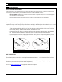
Surge protectors can be purchased at most hardware stores. The manufacturer recommends a single outlet surge protector with a
UL 1449 rating as a Transient Voltage Surge Suppressor (TVSS) with a UL suppressed voltage rating of 400V or less and an
electrical rating 120VAC, 15 amps.
This treadmill must be grounded to reduce the risk of electrical shock. Grounding provides a path of least resistance for electric
current, should the treadmill malfunction. This treadmill is equipped with an electrical cord that has an equipment-grounding
conductor and a grounding plug. Always plug the power cord into a surge protector, and plug the surge protector into an
appropriate outlet that is properly installed and grounded in accordance with all local codes and ordinances.
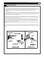
This product is for use on a nominal 120-volt circuit, and has a grounding plug that looks like the plug illustrated in the drawing
below.
GFCI outlets and GFCI / AFCI Circuit Breakers are NOT recommended for use on this product. GFCI outlets and GFCI / AFCI
Circuit Breakers may cause this equipment to function improperly.

www.smoothfitness.com
5
POWER REQUIREMENTS
Alimentation :
UN MAUVAIS BRANCHEMENT DU CONNECTEUR DE MISE À LA TERRE DE L’ÉQUIPEMENT POURRAIT PROVOQUER UN
CHOC ÉLECTRIQUE. EN CAS DE DOUTE, CONSULTER UN ÉLECTRICIEN OU UN RÉPARATEUR QUALIFIÉ POUR SAVOIR
SI LE PRODUIT EST CORRECTEMENT MIS À LA TERRE. NE PAS MODIFIER LA FICHE FOURNIE AVEC LE PRODUIT. SI
ELLE N’ENTRE PAS DANS LA PRISE, FAIRE INSTALLER UNE PRISE APPROPRIÉE PAR UN ÉLECTRICIEN
PROFESSIONNEL.
Ce tapis roulant pourrait être gravement endommagé en cas de changement soudain de tension dans votre alimentation électrique.
Les conditions météorologiques ou la mise sous tension ou hors tension d’autres appareils électriques peuvent provoquer des
pointes de tension, des surtensions ou un brouillage. Pour réduire la possibilité que le tapis soit endommagé, toujours utiliser un
limiteur de surtension (non inclus) avec votre tapis roulant.
Il est possible d’acheter des limiteurs de surtension dans la plupart des quincailleries. Le fabricant recommande un limiteur de
surtension UL 1449 à prise unique comme suppresseur de tension transitoire (TVSS) ayant un taux de suppression de tension de
400 V ou moins et une tension électrique de 110 V C.A., 15 A.
Ce tapis roulant doit être mis à la terre pour réduire le risque de choc électrique. La mise à la terre fournit une voie de moindre
résistance au courant électrique en cas de mauvais fonctionnement du tapis roulant. Ce tapis roulant est équipé d’un cordon
électrique avec un conducteur de mise à la terre et une fiche de mise à la terre. Brancher toujours le cordon électrique dans un
limiteur de surtension et brancher le limiteur de surtension dans une prise appropriée, correctement installée et mise à la terre
conformément à tous les codes locaux et ordonnances.
Ce produit doit être utilisé avec un circuit nominal de 110 volts et à une fiche de mise à la terre qui ressemble à celle illustrée ci-
dessous.
Les prises avec disjoncteur de fuite de terre et les disjoncteurs de fuite de terre ne sont PAS recommandés pour ce produit. Les
prises avec disjoncteur de fuite de terre et les disjoncteurs de fuite de terre pourraient provoquer un mauvais fonctionnement de cet
équipement.

6 675i TREADMILL
BEFORE YOU BEGIN
Open the boxes:
Open the boxes of your new equipment. Inventory all parts included in the boxes, and Supplied Hardware lists
on page 7 for a full count of the parts included. If you are missing any parts or have any questions contact us
directly at 888-800-1167
Gather your tools:
Before you begin, make sure that you have gathered all the necessary tools you may require to assemble the unit
properly. Having all of the necessary equipment at hand will save time and make the assembly quick and hassle-free.
Clear your work area:
Make sure that you have cleared away a large enough space to properly assemble the unit. Make sure the space is
free from anything that may cause injury during assembly. After the unit is fully assembled, make sure there is a
comfortable amount of free area around the unit for unobstructed operation.
Invite a friend:
Some of the assembly steps may require heavy lifting. It is recommended that you obtain the assistance of another
person when assembling this product.
User Weight Limitation:
Please note that there is a weight limitation for this product. If you weigh more than 350LBS (Approx. 160 Kgs). It is
not recommended that you use this product. Serious injury may occur if the user’s weight exceeds the limit shown
here. This product is not intended to support users whose weight exceeds this limit.
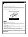
Care and maintenance:
The safety level can be maintained only if it is examined for damage and wear.
Replace any defective components immediately and stop all use of the equipment until repaired.
Always take care when mounting the equipment. Straddle the equipment by placing your feet on the straddle rails.
Dismount from the equipment only after all parts have stopped.
Always check the wear and tear components like pulley, belts, etc.…To prevent injury.
There is an emergency stop, in the form of a SAFETY KEY, to prevent injury; you can stop the treadmill immediately
by actuating the emergency stop for emergency dismount.

www.smoothfitness.com
7
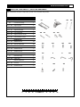
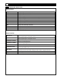
SUPPLIED COMPONENTS / SUPPLIED HARDWARE
This list identifies the major components you will use to assemble this product.
No. Description Qty.
A1
Treadmill Base
1
A2
Console Assembly
1
675i -301
Right Upright
1
675i -302
Left Upright
1
675i -307
Right Handle Bar
1
675i -308
Left Handle Bar
1
675i -310
Right Protective Cover
1
675i -311
Left Protective Cover
1
Hardware Kit
675i -303
M8x15mm Bolt
14
675i -304
M8 Curve Washer
14
675i -305
M4x15mm Bolt
2
675i -306
M6x15mm Bolt
2
675i -312
M6x65mm Bolt
2
A
5mm Allen Key
1
B
6mm Allen Key
1
675i -209
Safety Key
1
C
Silicone Lubricant
1
675i -309
End cap
4
675i -313
M4x10mm Bolt
4
Millimeters
A1
311 310
302 301
A2
308 307
304
306
305
303
B
209
A
312
C
309
313

8 675i TREADMILL
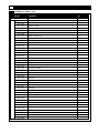
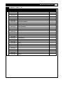
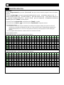
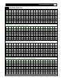
COMPLETE PARTS LIST
Item No. Description Qty.
675i -100
675i -101
Running deck frame
1
675i -102
Front roller
1
675i -103
Rubber cushion
8
675i -104
Running deck
1
675i -105
Running belt
1
675i -106
Rear roller
1
675i -107
Motor control board
1
675i -108
Upper motor cover
1
675i -109
Fixing bracket, motor
1
675i -110
Bolt M4*15mm
2
675i -111
Front mobile wheel
2
675i -112
Bolt M4*10mm
8
675i -113
Base frame
1
675i -114
Speed sensor
1
675i -115
On-off switch
1
675i -116
Bolt M8*30mm
2
675i -117
Power breaker
1
675i -118
End cap-2
2
675i -119
Running deck frame end cap
2
675i -120
Spring washer M8
2
675i -121
Drive belt
1
675i -122
Left roller cover
1
675i -123
Right roller cover
1
675i -124
Side rein
2
675i -125
Stud-1
2
675i -126
Washer, stud
2
675i -127
Bolt M8*15mm
2
675i -128
Bushing
4
675i -129
Lower locking tube
1
675i -130
Upper locking tube
1
675i -131
Lower motor cover
1
675i -132
Rear wheel
2
675i -133
Spacer
2
675i -134
Incline motor
1
675i -135
DC motor
1
675i -136
Lift arm
1
675i -137
Adjustment pad
2
675i -138
Bolt M8*15mm
2
675i -139
Bolt M3*6mm
2
675i -140
Bolt M8*40mm
2

www.smoothfitness.com
9
COMPLETE PARTS LIST
Item No. Description Qty.
675i -141
Bolt M8*40mm 3
675i -142
Nut M8 2
675i -143
Bolt M10*45mm 1
675i -144
Nut M10 1
675i -145
Spring washer M8 5
675i -146
Bolt M8*15mm 2
675i -147
Horizontal adjustment 2
675i -148
Bolt M8*140mm 1
675i -149
Nut M8 5
675i -150
Bolt 5/16"*135mm 1
675i -151
Lower console wire 1
675i -152
Spring washer M8 1
675i -153
Bolt M4*10mm-1 8
675i -154
Bolt M4*10mm-2 4
675i -155
Power cord 1
675i -156
Washer, stud 2
675i -157
Bolt M8*40mm 2
675i -158
Bolt M8*70mm 3
675i -159
Electric wire cover 1
675i -160
Stud-2 2
675i -161
Wire clip 4
675i -162
Bolt M5*12mm 4
675i -163
Air shock 1
675i -164
Bolt M8*15mm 2
675i -165
Bolt M8*55mm 1
675i -166
Bolt M8*60mm 1
675i -167
Adaptor 1

10 675i TREADMILL
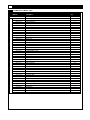
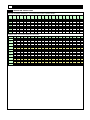
COMPLETE PARTS LIST
Item No. Description Qty.
675i -200
675i -201
Console frame
1
675i -202
Console housing
1
675i -203
Bolt M4*10mm
6
675i -204
Handle pulse sensor
2
675i -205
Bolt M4*25mm
2
675i -206
IHP
1
675i -207
Console cover
1
675i -208
Tablet Shelf
1
675i -209
Ring core
1
675i -210
Safety key
1
675i -211
Bolt M3*8mm
18
675i -212
Operational button & overlay
1set
675i -213
Audio jack
1
675i -214
Panel, console
1
675i -215
Bolt M3*6mm
13
675i -216
Bolt M4*10mm
4
675i -217
Speaker
2
675i -218
Speaker fixer
2
675i -219
Handle grip foam
2
675i -220
Handle button cover
2
675i -221
Bolt M4*12mm
4
675i -222
Safety key base
1
675i -223
Bolt M3*6mm
4
675i -224
Lower console cover
1
675i -225
Bottle Holder
1
675i -226
Bolt M3*6mm
2
675i -227
Bolt M4*12mm
14
675i -228
Bolt M3*10mm
2
675i -229
Console wire
1
675i -230
USB charger
1
675i -231
Handle button sticker
2
675i -232
Hand pulse wire
1
675i -233
Handle button wire
2
675i -234
Receiver wire
1
675i -235
Receiver
1
675i -236
Software update cap
1
675i -237
-
-
675i -238
Tablet left support
1
675i -239
Table right support
1
675i -240
Spring
2
675i -241
M4 washer
2
675i -242
Washer
2
675i -243
Bolt M2.6*8mm
2
675i -244
Adaptor wire
1

www.smoothfitness.com
11
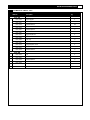
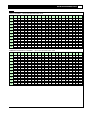
COMPLETE PARTS LIST
Item No. Description Qty.
675i -300
675i -301
Right upright 1
675i -302
Left upright 1
675i -303
Bolt M8*15mm 14
675i -304
M8 curve washer 14
675i -305
Bolt M4*15mm 2
675i -306
Bolt M6*15mm 2
675i -307
Right handle bar 1
675i -308
Left handle bar 1
675i -309
End cap 4
675i -310
Right protective cover 1
675i -311
Left protective cover 1
675i -312
Bolt M6*65mm 2
675i -313
Bolt M4*10mm 4
675i -400
675i -401
Fan 1
675i -402
Fan cover 1
675i -403
Bolt M3*30mm 4
675i -404
Bolt M3*8mm 4

12 675i TREADMILL
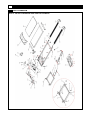
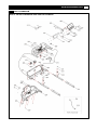
PARTS DIAGRAM
MOST OF THE PARTS SHOWN HERE HAVE BEEN PRE-ASSEMBLED

www.smoothfitness.com
13
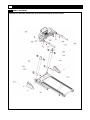
PARTS DIAGRAM
MOST OF THE PARTS SHOWN HERE HAVE BEEN PRE-ASSEMBLED.

14 675i TREADMILL
PARTS DIAGRAM
A MAJORITY OF THE PARTS SHOWN HERE HAVE BEEN PREASSEMBLED AT THE FACTORY.

www.smoothfitness.com
15
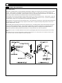
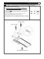
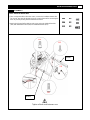
ASSEMBLY – PLEASE READ ALL STEPS BEFORE BEGINNING YOUR WORK.
STEP1: Assemble Console Mast to Base Frame.
NOTE:
Make sure all wires are recessed into the frame. DO NOT trap or
pinch. DO NOT tighten any bolts until STEP2.
When attaching the Right
upright (301) first attach the Lower Console Wire to the
fish wire in the upright. This will allow you to pull the data cable up through the
upright during installation.
1). Attach Left and Right Uprights into base frame, and secure using 6 x
M8x15mm Bolt (303) AND 6 x M8 Curve Washer (304).
Note: Hand tighten only do not fully tighten the bolts until step 2 is complete.
303
X6
304 X6
Bolts should be hand tight only
Green plastic wrap
Clear plastic wrap

16 675i TREADMILL
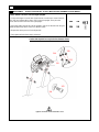
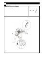
ASSEMBLY – PLEASE READ ALL STEPS BEFORE BEGINNING YOUR WORK.
STEP 2: Attach Console to Left and Right Uprights
1). Connect the Upper Console Wire (229) from the console set to Lower Console
Wire (151) and Adaptor Wire (244 to 154) in the right upright, Then place the
excess wire and the connectors into right upright.
2). Place the entire console set onto the uprights, and secure the left side using 4 x
M8x15mm Bolt (303) with 4 x M8 Curve Washer (304).
3). Repeat the above process for the Right side.
4). Fully tighten all bolts from step 1 and step 2.
303
X8
304 X8
Caution Pinch point! Do not pinch wires between frame.
229
151
303
304
244
154
Tighten all bolts and fasteners now

www.smoothfitness.com
17
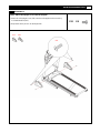
ASSEMBLY
STEP 3: Attach the Handle Bars
1). Take out right handle bar from the carton, connect the handlebar button wire.
The excess wire must be placed inside the console frame after connecting the
wires to prevent pinching the wire between the frame
2). Attach the right and left handle bar and secure using the 2xM4x15mm bolt
(305) with 2xM6x15mm bolt (306) and 2xM6x65mm bolt (312).
305
X2
306
X2
312
X2
Tighten all bolts and fasteners now
233
305
306
312
Speed
Incline

18 675i TREADMILL
ASSEMBLY
Step4: Attach the console to the console mast
1). Put 4 plastic caps (309) into console lower cover.
309 X4
309

www.smoothfitness.com
19
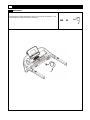
ASSEMBLY
STEP 5: Attach the upright covers onto the uprights
1). Attach the Left Upright Cover (311) onto the Left upright and secure using
2 x M4x10mm Bolt (313).
2). Repeat the above process for the Right side.
313 X4
311 310
313

20 675i TREADMILL
ASSEMBLY
STEP 6:
Insert Safety Key (209) into Bottom Center of Console prior to operation. Your
treadmill will not Function with out the safety key.
209 X1
209
La page est en cours de chargement...
La page est en cours de chargement...
La page est en cours de chargement...
La page est en cours de chargement...
La page est en cours de chargement...
La page est en cours de chargement...
La page est en cours de chargement...
La page est en cours de chargement...
La page est en cours de chargement...
La page est en cours de chargement...
La page est en cours de chargement...
La page est en cours de chargement...
La page est en cours de chargement...
La page est en cours de chargement...
La page est en cours de chargement...
La page est en cours de chargement...
La page est en cours de chargement...
La page est en cours de chargement...
La page est en cours de chargement...
La page est en cours de chargement...
-
 1
1
-
 2
2
-
 3
3
-
 4
4
-
 5
5
-
 6
6
-
 7
7
-
 8
8
-
 9
9
-
 10
10
-
 11
11
-
 12
12
-
 13
13
-
 14
14
-
 15
15
-
 16
16
-
 17
17
-
 18
18
-
 19
19
-
 20
20
-
 21
21
-
 22
22
-
 23
23
-
 24
24
-
 25
25
-
 26
26
-
 27
27
-
 28
28
-
 29
29
-
 30
30
-
 31
31
-
 32
32
-
 33
33
-
 34
34
-
 35
35
-
 36
36
-
 37
37
-
 38
38
-
 39
39
-
 40
40


Smooth Fitness 6.75 Manuel utilisateur
- Catégorie
- Tapis de course
- Taper
- Manuel utilisateur
dans d''autres langues
- English: Smooth Fitness 6.75 User manual
Documents connexes
-
 Smooth Fitness 835 Manuel utilisateur
-
 Smooth Fitness 5.65S Manuel utilisateur
-
 Smooth Fitness 9.65LC Manuel utilisateur
-
 Smooth Fitness Treadmill 9.65LC Manuel utilisateur
-
 Smooth Fitness smt-935bt Manuel utilisateur
-
 Smooth Fitness 7.35 R Manuel utilisateur
-
 Smooth Fitness 9.65TV Manuel utilisateur
-
 Smooth Fitness 675iO/BT Manuel utilisateur


