Falcon Professional+ 110 User Manual & Installation & Service Instructions
- Catégorie
- Fours
- Taper
- User Manual & Installation & Service Instructions
Ce manuel convient également à

ArtNo.000-0008 Falcon logo shaded
ArtNo.000-0012 Professional + logo
&
Installation & Service Instructions
&
Instructions d'installation & d'entretier
U109772-05

Contents
Before you start... 1
Cooker Overview 2
The Griddle 4
The Glide-out Grill 5
The Ovens 5
The Clock 6
Tips on Cooking with the Timer 8
General Oven Tips 8
Oven Cooking Guide 9
Oven shelves 10
The Handyrack 10
Main Oven Light 11
The Browning Element 11
Storage 11
Cleaning your Cooker 11
Troubleshooting 13
Installation 15
Conversion to LP gas 21
Servicing 22
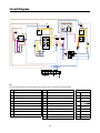
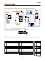
Circuit Diagram 26
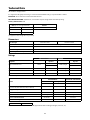
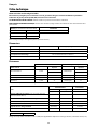
Technical Data 27

1
Before you start...
Thank you for buying the Professional
+
cooker. It should give
you many years trouble-free cooking if installed and operated
correctly. It is, therefore, important that you read this section
before you start, particularly if you have not used a dual fuel
cooker before.
This appliance is designed for domestic cooking only. Using
it for any other purpose could invalidate any warranty or
liability claim. In particular, the oven should NOT be used for
heating the kitchen - besides invalidating claims, this wastes
fuel and may overheat the control knobs.
In the UK, the cooker must be installed by a Gas Safe
registered engineer. The electrical installation should be in
accordance with BS 7671. Otherwise, all installations must be
in accordance with the relevant instructions in this booklet,
with the relevant national and local regulations, and with the
local gas and electricity supply companies’ requirements.
Ensure that the gas supply is turned on and that the cooker is
wired in and switched on (the cooker needs electricity).
The cooker should be serviced only by a qualified service
engineer, and only approved spare parts should be used.
Always allow the cooker to cool and then switch it off at the
mains before cleaning or carrying out any maintenance work,
unless specified otherwise in this guide.
When you first use your cooker it may give off a slight odour.
This should stop after a little use.
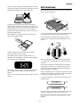
Before using for the first time, make sure that all packing
materials have been removed and then, to dispel
manufacturing odours, turn the ovens to 200°C and run for an
hour.
Before using the grill for the first time you should also turn on
the grill and run for 30 minutes with the grill pan in position,
pushed fully back, and the grill door open.
• DO NOT turn electric switches on or off.
• DO NOT smoke
• DO NOT use naked flames
• DO turn off the gas at the meter or cylinder
• DO open doors and windows to get rid of the gas
• DO keep people away from the area affected
• Call your gas supplier.
If you are using natural gas in the UK, ring the National Grid
on: 0800 111 999.
The use of a gas cooking appliance results in the production
of heat and moisture in the room in which it is installed.
Therefore, ensure that the kitchen is well ventilated: keep
natural ventilation holes open or install a powered cooker
hood that vents outside. If you have several burners on, or
use the cooker for a long time, open a window or turn on an
extractor fan.
When the oven is on, DO NOT leave the oven door open for
longer than necessary – otherwise, the control knobs may
become very hot.
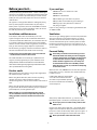
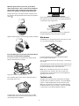
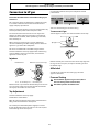
Cooking high moisture content foods
can create a ‘steam burst’ when the
oven door is opened. When opening
the oven stand well back and allow any
steam to disperse.
ArtNo.324-0001 Steam burst
Always keep combustible materials, e.g. curtains, and
flammable liquids a safe distance away from your cooker.
Use dry oven gloves when applicable – using damp gloves
might result in steam burns when you touch a hot surface.
Do not use a towel or other bulky cloth in place of a glove – it
might catch fire if brought into contact with a hot surface.

2
Foods for frying should be as dry as possible. Frost on frozen
foods or moisture on fresh foods can cause hot fat to bubble
up and over the sides of the pan. Carefully watch for spills or
overheating of foods when frying at high or medium high
temperatures. Never try to move a pan of hot fat, especially a
deep fat fryer. Wait until the fat is cool.
Do not use the top of the flue (the slot along the back of
the cooker) for warming plates, dishes, drying tea towels or
softening butter.
Take care that no water seeps into the appliance.
Only certain types of glass, glass-ceramic, earthenware or other
glazed containers are suitable for hotplate cooking; others may
break because of the sudden change in temperature.
In the interests of hygiene and safety, the cooker should be
kept clean at all times as a build up in fats and other food
stuff could result in a fire.
Clean only the parts listed in this guide.
Clean with caution. If a wet sponge or cloth is used to wipe
spills on a hot surface, be careful to avoid steam burns. Some
cleansers can produce noxious fumes if applied to a hot
surface.
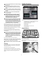
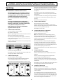
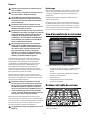
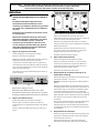
Cooker Overview
ArtNo.270-0014 110 Professional+ cooker
The Professional
+
110 Dual Fuel has the following features:
• Six hotplate burners, including a wok burner, with a
FSD (Flame Safety Device) on each one.
• A griddle and wok cradle.
• A control panel.
• A glide-out grill.
• A conventional oven and a fan oven.
• A storage drawer.
ArtNo.270-0013 110 Proplus gas hob layout
The drawing by each of the central knobs indicates which
burner that knob controls.
Each burner has an FSD that prevents the flow of gas if the
flame goes out.
ArtNo.311-0018 Hob burner FSD details

3
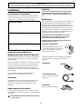
To light a burner, press the igniter button, and push in and
turn a knob to the high position indicated by the large flame
symbol (
):
ArtNo.270-0001
Proplus control to high
Adjust the flame height to suit by turning the knob clockwise.
ArtNo.270-0003
Proplus control to low
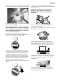
Ensure that the flames are under the pans. Using a lid will
help the contents boil more quickly.
ArtNo.311-0001 Right pans gas
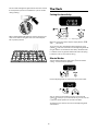
Large pans should be spaced well apart.
Pans and kettles with concave bases or down turned base
rims should not be used:
ArtNo.311-0002 Pan with rim
Simmering aids, such as asbestos or mesh mats, are NOT
recommended. They will reduce burner performance and
could damage the pan supports:
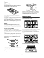
You should also avoid using unstable and misshapen pans
that may tilt easily, and pans with a very small base diameter,
e.g. milk pans, single egg poachers.
ArtNo.311-0004 Tipping wok
The minimum recommended pan diameter is 120mm. The
maximum allowable pan base diameter is 250mm.
The Wok burner is designed to provide even heat over a large
area. It is ideal for large pans and stir frying.
ArtNo.311-0005 Wok burner & pan support
For heating smaller pans, the aforementioned hotplate
burners may be more efficient.
You can remove the burner parts for cleaning – see ‘Cleaning
your cooker’.
You should wipe the enamel top surface of the cooker around
the hotplate burners as soon as possible after spills occur. Try
to wipe them off while the enamel is still warm.
Note:
The use of aluminium pans may cause metallic
marking of the pan supports. This does not affect the
durability of the enamel and may be cleaned off with an
appropriate metal cleaner.
The Wok cradle is designed to fit a Professional 35cm Wok
(available from our cookware collection – Part Code RM095).
If you use a different Wok, make sure that it fits the cradle.
Woks vary very widely in size and shape. It’s important that
the Wok sits down on the pan support – however, if the Wok
is too small, the cradle will not support it properly.

4
ArtNo.311-0006 Correct wok sizes
The cradle should be used on the triple ring Wok burner only.
When you fit the cradle, check that the Wok is properly
located on the front and rear fingers and that it is supported
properly on a pan support.
ArtNo.311-0007 Wok stand close-up
Make sure that the cradle is stable and that the Wok is sitting
level in the ring.
The cradle will get very hot in use – allow plenty of time for it
to cool before you pick it up.
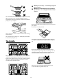
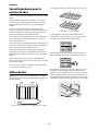
The Griddle
ArtNo.110-0013 Positioning the griddle on hotplate (right)
The griddle fits the centre left pan support, front to back. It is
designed for cooking food on directly. Don’t use pans of any
kind on it. The griddle surface is non-stick and metal cooking
utensils (e.g. spatulas) will damage the surface. Use heat
resistant plastic or wooden utensils.
ArtNo.110-0014 Positioning the griddle on hotplate (wrong)
ArtNo.090-0005 Positioning the griddle
Position the griddle over the hotplate burners resting on the
pan support.
Check that it is securely located.
ArtNo.311-0009 Oil on griddle
The griddle can be lightly brushed with cooking oil before
use. Light the hotplate burners. Adjust the flame heights to
suit.
ArtNo.301-0003 Clock display at 5mins
Preheat the griddle for a maximum of 5 minutes before
adding food. Leaving it longer may cause damage. Turn the
control knobs towards the low position, marked with the
small flame symbol, to reduce the burner flames.
ArtNo.311-0008 Griddle positioning
Always leave space around the griddle for the gases to
escape. Never fit two griddles side by side.

5
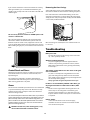
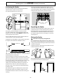
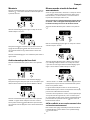
The Glide-out Grill
Open the door and pull the grill pan carriage forward using
the handle:
ArtNo.331-0001Grill pan pulled forwards
The grill has two elements that allow either the whole area of
the pan to be heated or just the right-hand half.
Adjust the heat to suit by turning the knob. To heat the whole
grill, turn the knob clockwise:
ArtNo.270-0004
Proplus grill control
1
1
2
2
3
3
0
To heat the right-hand half, turn it anticlockwise. The neon
indicator light by the grill control will come on.
For best results, you should slide the carriage back into the
grill chamber and preheat the appropriate part(s) of the grill
for two minutes. The grill trivet can be removed and the food
placed on it while you are waiting for the grill to preheat.
Once the grill has preheated, slide the carriage out again.
With the trivet back in place with the food on it, slide the
carriage back into the grill chamber. Ensure that it is pushed
right in.
The grill pan grid can be turned over to give two grilling
positions:
ArtNo.331-0002 Grill pan high/low position
Don’t leave the grill on for more than a few moments, without
the grill pan underneath it.
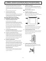
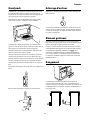
The Ovens
References to 'left-hand' and 'right-hand' ovens apply as viewed
from the front of the appliance.
The left-hand oven is a conventional oven (see below), while
the right-hand oven is a fanned oven that can be timed.
ArtNo.322-0002 Conventional oven
The left-hand conventional oven is fitted with two heating
elements, one visible in the top of the oven and the second
under the oven base. Be careful to avoid touching the top
element and element deflector when placing or removing
items.
ArtNo.321-0002 Fan assisted oven
This oven circulates hot air continuously, which means
faster, more even cooking. The recommended cooking
temperatures for a fanned oven are generally lower than for a
non-fanned oven.
Turn the particular oven knob to the desired temperature:
ArtNo.270-0005 Proplus
electric oven control
140
100
180
220
0

6
The oven indicator light will glow until the oven has reached
the temperature you selected. It will then cycle on and off
during cooking:
ArtNo.270-0006 Proplus
oven control light
140
100
180
220
0
When cooking foods with high water content, there may be
some steam visible at the grille at the rear of the hotplate.
This is perfectly normal.
ArtNo.110-0007 110 Oven steam out of back
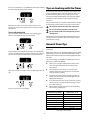
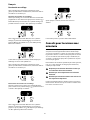
The Clock
ArtNo.300-0004 2-button clock annotated
A – Timer knob, B – Adjusting knob
When the clock is first connected, the display flashes ( 0.00)
and (
) alternately.
To set the time, turn and hold the Timer knob to the clock
symbol (
) and at the same time turn the Adjusting knob left
or right until the clock shows the time of day. Remember this
is a 24-hour clock. Let go of the Timer knob and it will spring
back to the vertical, oven manual setting.
Turn the Timer knob to the right to the (
) minute minder
setting – it should click into position:
ArtNo.300-0005 2BC
minute minder setting
Use the Adjusting knob to set the time you need as below:
ArtNo.300-0006 2BC
minute minder setting 2
You can either turn the knob back to the vertical manual
setting (
) to keep an eye on the time of day, or leave it in the
(
) minute minder position as the time ticks down.
To stop the beeper when it sounds, turn the Adjusting knob
anticlockwise.

7
Turn the Timer knob to the () position.
ArtNo.301-0007 2BC
Stopping the oven 1
Use the Adjusting knob to set the time at which the oven is
to stop. You can set the oven to turn on at any time over the
following 24-hour period. AUTO shows in the display:
ArtNo.301-0008 2BC
Stopping the oven 2
Turn the Timer knob to the bottom ‘Auto’ setting. Once the set
time is reached, the beeper sounds. Turn the Timer knob to
the vertical (
) to return to manual cooking.
Before you set the clock, decide on both the ‘cook time’, which
is the period of time you want the oven to cook, and the ‘stop
time’, which is the time of day at which you want the oven to
stop cooking.
Turn the Timer knob to the (
) position:
ArtNo.301-0009 2BC
Setting the cooking timer
Use the Adjusting knob to set the ‘cooking time’ you need:
ArtNo.301-0010 2BC
Setting the cooking time
Turn the Timer knob to the (
) position. The display will
show the current time of day plus the ‘cook time’ you just set.
Use the Adjusting knob to set the ‘stop time’ you need:
ArtNo.301-0008 2BC
Stopping the oven 2
The ‘stop time’ is displayed, followed by 'AUTO'. Set the oven(s)
to the cooking temperature you need Turn the Timer knob to
the ‘Auto’ setting.
When your cooking is finished, the beeper sounds. Turn the
Timer knob to the vertical (
) to return to manual cooking.
If you are out, don’t worry about the beeper going off – it
stops on its own after a while. When you return, turn the
Timer knob to the vertical (
) to return to manual cooking.
You can cancel any automatic settings by briefly turning the
Timer knob to the clock symbol (
) and then releasing it.
When the key lock is activated, the left-hand oven can be
operated as usual but the right-hand oven is locked and will
not come on.
Make sure that the clock is in manual mode and cancel any
active programs.
Turn and hold the Timer knob to the clock symbol (
) for
about 8 seconds. ‘On’ appears on the display:
Art No. 301-0011 2BC
Activating the key lock 1
Keep holding the Timer knob turned to the clock symbol (
)
and turn the Adjusting knob clockwise until the key symbol
(
) and ‘Of’ shows on the display. Let go of the knobs.
ArtNo.301-0012 2BC
Activating the key lock 2

8
The oven is now locked, as is confirmed by the display showing
the time of day alongside the key symbol:
ArtNo.301-0013 2BC
Activating the key lock 3
When the key lock is activated, the left-hand oven can be
operated as usual but the right-hand oven is locked and will
not come on.
Turn and hold the Timer knob to the clock symbol (
) for
about 8 seconds. ‘Of’ will appear on the display.
ArtNo.301-0014 2BC
Deactivating the key lock 1
Keep holding the Timer knob turned to the clock symbol (
)
and turn the Adjusting knob clockwise until the key symbol (
)
goes out on the display and ‘On’ shows. Let go of the knobs.
After a few seconds, the display reverts to showing the time of
day:
ArtNo.301-0016 2BC
Deactivating the key lock 3
The oven can now be used normally.
Tips on Cooking with the Timer
If you want to cook more than one dish, choose dishes that
require approximately the same time. However, dishes can
be ‘slowed down’ slightly by using small containers and
covering them with aluminium foil, or ‘speeded up’ slightly
by cooking smaller quantities or placing them in larger
containers.
Very perishable foods such as pork or fish should be avoided
if a long delay period is planned, especially in hot weather.
Whole poultry must be thoroughly defrosted before being
placed in the oven. Check that meat and poultry are fully
cooked before serving.
General Oven Tips
The wire shelves should always be pushed firmly to the back
of the oven.
Baking trays, meat tins, etc., should be placed level in the middle
of the oven’s wire shelves. Keep all trays and containers away
from the sides of the oven otherwise overbrowning of the food
may occur.
For even browning, the maximum recommended size for a
baking tray is 340mm by 340mm.
Always leave a ‘fingers width’ between dishes on the
same shelf. This allows the heat to circulate freely
around them.
The Cook & Clean oven liners (see 'Cleaning your
Cooker') work better when fat splashes are avoided.
Cover meat when cooking.
To reduce fat splashing when you add vegetables to
hot fat around a roast, dry them thoroughly or brush
lightly with cooking oil.
If you want to brown the base of a pastry dish, preheat
a baking tray for 15 minutes before placing the dish in
the centre of the tray.
Where dishes may boil and spill over during cooking,
place them on a baking tray.
ArtNo.050-0006 Gas temperature conversion table
Temperature conversion table

9
ArtNo.050-0003A - Cooking table - electric & fan
Shelf
position
C
C
C
C
C
C
C
C
C
C
C
C
C
T
C/B
C/B
C/B
C/B
C/B
C/B
C
C
C
C
C
C
C
C
C
C
C
C
C/B
C/T
Food
Meat
Beef (no bone)
Lamb
Pork
Poultry
Chicken
Turkey
Duck
Casserole
Yorkshire pudding
Fish
Fillet
Whole
Steak
Cake
Very rich fruit - Christmas,
wedding, etc.
Fruit 180 mm tin
Fruit 230 mm tin
Madeira 180 mm
Queen cakes
Scones
Victoria sandwich
180 mm tin
210 mm tin
Desserts
Shortcrust tarts
Fruit pies
Tartlets
Puff pastry
Meringues
Baked egg custard
Baked sponge pudding
Milk pudding
Bread
Approximate cooking time
30-35 minutes per 500g +30-35 minutes.
20-25 minutes per 500g +20-25 minutes.
30-35 minutes per 500g +30-35 minutes.
25-30 minutes per 500g +25-30 minutes.
35-40 minutes per 500g +35-40 minutes.
25-30 minutes per 500g +25-30 minutes.
20-25 minutes per 500g +20-25 minutes.
15-20 minutes per 500g +15-20 minutes.
20 minutes per 500g +20 minutes.
15 minutes per 500g +15 minutes.
25-30 minutes per 500g.
20 minutes per 500g.
2-4 hours according to recipe.
Large tins 30-35 minutes; individual 10-20 minutes.
15-20 minutes.
15-20 minutes per 500g.
Steaks according to thickness.
45-50 minutes per 500g of mixture.
2-2½ hours.
Up to 3½ hours.
80-90 minutes.
15-25 minutes.
10-15 minutes.
20-30 minutes.
30-40 minutes.
20-30 minutes on a preheated tray.
35-45 minutes.
10-20 minutes according to size.
20-40 minutes according to size.
2-3 hours.
45-60 minutes.
40-45 minutes.
2 to 3 hours.
20-30 minutes.
Temperature
°C
150
190
150
190
150
190
150
190
150
190
150
190
130-140
210
180
180
180
130
140
140
150
180
210
170
170
190
190
190
220
90
150
180
130-140
210
Temperature
°C
160
200
160
200
160
200
160
200
160
200
160
200
140-150
220
190
190
190
140
150
150
160
190
220
180
180
200
200
200
230
100
160
190
140-150
220
Conventional Oven Fan Oven
Thoroughly thaw frozen joints before
cooking. Meat may be roasted at
220°C (210°C for fan oven) and the
cooking time adjusted accordingly.
For stuffed and rolled meats, add
approximately 10 minutes per 500g,
or cook at 200°C (190°C) for 20
minutes then 160°C (150°C) for the
remainder.
For stuffed poultry, you could cook
at 200°C (190°C) for 20 minutes
then 160°C (150°C) for remainder.
Do not forget to include the weight
of the stuffing.
For fresh or frozen prepacked
poultry, follow instructions on the
pack. Thoroughly thaw frozen
poultry before cooking.
Using the conventional oven: when
two tier cooking leave at least one
runner space between shelves.
Position the baking tray with the
front edge along the front of the
oven shelf.
ArtNo.050-0001 Gas cooking table
Using the conventional oven: for
even browning the maximum size of
baking tray recommended is 340mm
x 340mm. This ensures free heat
circulation.
If cooking a two tier load, the trays
should be interchanged
approximately halfway though the
cooking time.
Up to three tiers can be cooked in a
fan oven at the same time but make
sure to leave at least one runner
space between each shelf being
cooked on.
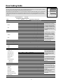
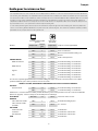
Oven Cooking Guide
ArtNo.050-0007
Oven shelf positions
Oven Shelf Positions
Top
Centre
Base
The oven control settings and cooking times given in the table below are intended to be used only as a guide. Individual
tastes may require the temperature to be altered to provide a preferred result.
When baking in the right-hand fanned oven, use the minimum cooking time shown in the table. Food is cooked at lower
temperature in a fan oven than in a conventional oven. When using recipes, reduce the temperature by 10°C and the
cooking time by 5-10 minutes. The temperature in the fanned oven does not vary with height in the oven so you can use
any shelf.

10
Oven shelves
ArtNo.320-0009 Oven shelf
A - Top view, B - Side view, C - Shelf guard, D - Front
The shelf guard should be at the back pointing upwards
In addition to the flat shelves, some models are supplied with
a drop shelf. The drop shelf increases the possibilities for oven
shelf spacing.
ArtNo.320-0010 Flat & drop shelves
A - Flat shelf, B - Drop shelf
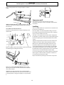
The oven shelves can be easily removed and refitted.
Pull the shelf forward until the back of the shelf is stopped by
the shelf stop bumps in the oven sides:
ArtNo.320-0011 Removing the shelf 1
Lift up the front of the shelf so the back of the shelf will pass
under the shelf stop and then pull the shelf forward:
ArtNo.320-0012 Removing the shelf 2
To refit the shelf, line up the shelf with a groove in the oven
side and push the shelf back until the ends hit the shelf stop.
Lift up the front so the shelf ends clear the shelf stops, and
then lower the front so that the shelf is level and push it fully
back.
ArtNo.320-0013 Removing the shelf 3
The Handyrack
The maximum weight that can be held by the Handyrack is
5.5kg (12lb). It should only be used with the supplied roasting
tin, which is designed to fit the Handyrack. Any other vessel
could be unstable.
Additional roasting tins are available from our cookware
collection – Part Code RM027.
ArtNo.320-0014 Handyrack on LH door
The Handyrack fits to the left-hand Main Oven door only.
Food cooking on it is easy to attend to, because it’s accessible
when the door is open.
It can be fitted at two different heights. One of the oven
shelves must be removed and the other positioned to suit.
When the Handyrack is used in its highest position, other
dishes can be cooked on the bottom shelf position or base of
the oven.
When the Handyrack is used in its lowest position, other
dishes can be cooked on the second shelf position or base of
the oven.
To fit the Handyrack, locate one side of it on the door bracket:
ArtNo.320-0015
Fitting the Handyack 1
Then spring the other side out to clip it onto the other
bracket.
ArtNo.320-0016
Fitting the handyrack 2

11
Main Oven Light
Press the button to turn the light on:
ArtNo.320-0026
- Oven light
If the oven light fails, turn off the power supply before you
change the bulb. See the ‘Troubleshooting’ section for details
on how to change the bulb.
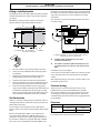
The Browning Element
The Browning Element is positioned in the top of the left-
hand oven. It can be used at the end of a normal cooking
period to give extra browning to au gratin dishes or give a
crisper finish to meat.
After the normal cooking is finished turn the left-hand
oven thermostat knob clockwise to the browning position,
indicated by (
) on the fascia panel.
Only the browning element will operate when the thermostat
is turned to this position. The top and base cooking elements
will automatically switch off.
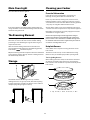
Storage
ArtNo.340-0001 110 drawer position
The bottom drawer is for storing oven trays and other
cooking utensils. It can get very warm, don’t store anything
in it that may melt or catch fire. The drawer can be removed
completely by pulling it right out and up.
ArtNo.340-0002 110 removing the drawer
Cleaning your Cooker
Isolate the electricity supply before carrying out any
thorough cleaning. Then allow the cooker to cool.
Never use paint solvents, washing soda, caustic cleaners,
biological powders, bleach, chlorine based bleach cleaners,
coarse abrasives or salt. Don’t mix different cleaning products
– they may react together with hazardous results.
All parts of the cooker can be cleaned with hot soapy water
– but take care that no surplus water seeps into the appliance.
Remember to switch on the electricity supply and reset the
clock before re-using the cooker.
We have developed a range of cleaning products that give
maximum performance without damaging the enamel and
painted surfaces. More information is available through either
the Cookware Collection brochure supplied with your cooker or
our website www.rangemaster.co.uk.
Some models have a separate trim ring, which fits on the
burner head.
The burner heads and caps can be removed for cleaning.
Make sure they are absolutely dry before replacing them.
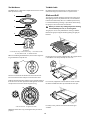
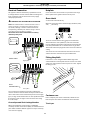
The Single Ring Burners
When refitting the burner head, ensure that the notch lines
up with the electrode or hole in the base. Check that the
burner head is level and that the cap is fitted centrally on the
burner head:
ArtNo.311-0013 Burner layout
A - Cap, B - Head, C - Notch, D - Electrode, E - Base

12
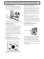
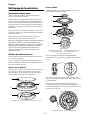
The Wok burner is a little more complicated but it can also be
taken apart for cleaning.
ArtNo.311-0014 Wok burner details
Wok burner
A - Inner burner cap, B - Outer burner cap, C - Inner burner head,
D - Outer burner head, E - Wok burner base
When reassembling the Wok burner, turn over the large base
ring and find the ‘D’ shaped area:
ArtNo.311-0015 Burner alignment
Turn the head until the ‘D’ matches the one on the burner
base. Turn the head over and place it on the burner base.
To fit the small inner burner, find the larger electrode notch in
the burner rim. Line this up with the white ignition electrode
and place the inner burner on the large base ring.
ArtNo.311-0016 Fitting the burner inner head
A - Electrode notch, B - Ignition electrode
Now fit the two burner caps, ensuring that they are seated
properly.
Recommended cleaning materials are hot soapy water, a
moistened soap pad, cream cleaner or a nylon scourer.
The grill pan and grid should be washed in hot soapy water.
After grilling meats or any foods that soil, leave to soak for a
few minutes immediately after use. Stubborn particles may
be removed from the grid using a nylon brush. Alternatively,
the grill pan can be washed in a dish washer.
The grill pan can be easily removed for cleaning as follows.
Remove the grill pan support frame by pulling the grill pan
forward:
ArtNo.331-0001Grill pan pulled forwards
Lift the grill pan clear of the support frame. The support frame
is held to the side rails by two clips on each side:
ArtNo.331-0003 Grill frame out, no pan
For each side, support the side rail with one hand and with
the other hand lift the frame up and out of the side clips:
ArtNo.331-0004 Removing the grill frame
For safety's sake, push the side rails back into the grill
chamber.

13
If you need to remove the side rails to facilitate the cleaning
of the grill chamber, you can unhook them from the grill
chamber sides and wipe the sides clean with a soft cloth and
mild detergent.
ArtNo.331-0005 Removing the grill rail
Once you have finished, hook the side rails back onto the
sides of the chamber. To refit the frame, pull the side rails
forward and, for each side in turn, support the side rail and
press the frame down into the side rails. Replace the grill pan.
When refitting the grill pan, ensure that the wide rim is at the
front:
ArtNo.331-0006 Grill pan plan
Avoid using any abrasive cleaners, including cream cleaners,
on brushed Stainless Steel surfaces. For best results, use a
liquid detergent.
The control panel and knobs, and doors, should only be
cleaned with a soft cloth wrung out in clean hot soapy water.
After cleaning, polish with a dry cloth.
The ovens have removable panels that have been coated with
a special enamel that partly cleans itself. This does not stop
all marks on the lining, but helps to reduce the amount of
manual cleaning needed.
The Cook & Clean panels work better above 200°C. If you do most
of your cooking below this temperature, occasionally remove the
panels and wipe with a lint free cloth and hot soapy water. The
panels should then be dried and replaced and the oven heated
at 200°C for about one hour. This will ensure the Cook & Clean
panels are working effectively.
Some of the lining panels can be removed for cleaning. You
will need to remove the shelves before removing the panels.
Each side of the oven is fixed with four fixing screws. You
don’t have to remove the screws to remove the oven linings.
Simply lift each side panel upwards and they will slide off the
screws. Then pull them forwards:
ArtNo.320-0008 Removing the oven lining
Once the linings are removed, the oven enamel interior can
be cleaned.
Troubleshooting
Noisy oven fan.
The tone of an oven fan may change as the oven heats
up – this is perfectly normal.
Grill not cooking properly.
Are you using the pan and trivet supplied with the
cooker? Is the pan being used on the runners, not the
floor of the compartment? Is the grill tray pushed fully
back to stop?
The knobs get hot when I use the oven or the grill.
Can I avoid this?
Yes, this is caused by heat rising from the oven or the
grill, and heating them up. Don’t leave the oven door
open. Make sure that the grill pan is pushed right back to
the ‘back stop’ when grilling.
Always grill with the grill compartment door open.
If there is an installation problem and I don’t get
my original installer to come back to fix it, who
pays?
You do. Service organisations will charge for their call-
outs if they are correcting work carried out by your
original installer. Therefore, it’s in your own interest to
keep track of this installer so that you can contact them
as required.
Power failure.
In the event of a failure in the electrical supply,
remember to reset the clock to ensure that the timed
oven continues to operate.

14
Food is cooking too slowly, too quickly, or
burning.
Cooking times may differ from your previous
oven. Check that you are using the recommended
temperatures and shelf positions –- see the oven
cooking guide. Then adjust the settings according to
your own individual tastes.
The oven is not cooking evenly.
Do not use a baking tray with dimensions larger than
those specified in the section on 'General Oven Tips'.
If you are cooking a large item, be prepared to turn it
round during cooking.
If two shelves are used, check that space has been left for
the heat to circulate. When a baking tray is put into the
oven, ensure that it is placed centrally on the shelf.
Check that the door seal is not damaged and that the
door catch is adjusted so that the door is held firmly
against the seal.
A dish of water when placed on the shelf should be the
same depth all over. (For example, if it is deeper at the
back, then the back of the cooker should be raised up or
the front lowered). If the cooker is not level arrange for
your supplier to level it for you.
The timed oven is not coming on when turned on
manually.
Is the power on? Is the clock illuminated? If not, there
may be something wrong with the power supply. Is the
cooker supply on at the isolator switch?
Has the time of day been set?
Is the key symbol (
) showing in the display to signify
that the oven is locked? See the 'Clock' section of the
instructions for more information on the key lock feature.
The timed oven is not coming on when automatic
cooking.
Has the oven knob been left in the OFF position by
mistake? Is the oven locked (see above)?
Oven temperature getting hotter as the cooker
gets older.
If turning the temperature down using the oven control
knob has not worked, or has only worked for a short
time, then you may need a new thermostat. This should
be fitted by a service person.
The oven light is not working.
The bulb has probably blown. You can buy a
replacement bulb (which is not covered under the
guarantee) from most electrical stores. Ask for an Edison
screw fitting 15W 240V lamp, FOR OVENS. It must be a
special bulb, heat resistant to 300°C. See the HELP leaflet
for spares by mail order.
ArtNo.324-0005 Oven light bulb
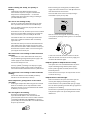
Before removing the existing bulb, turn off the power
supply and ensure that the oven is cool. Open the oven
door and remove the oven shelves.
Locate the bulb cover and unscrew it by turning it
anticlockwise (it may be very stiff):
ArtNo.320-0019 Oven light position
Now unscrew the existing bulb anticlockwise, taking
care to protect your fingers with a glove in case the bulb
should shatter.
ArtNo.324-0007 Unscrewing the bulb cover
Screw in the new bulb clockwise and then screw the
bulb cover back on. Turn on the electricity supply and
check that the bulb now lights.
Hotplate ignition or hotplate burners faulty.
Is the power on? Is the clock illuminated? If not, there
maybe something wrong with the power supply.
Are the sparker (ignition electrode) or burner slots
blocked by debris?
Are the burner trim and caps correctly located? See the
section on ‘Cleaning’.
Hotplate burners will not light.
Make sure that the burner parts have been replaced
correctly after wiping or removing for cleaning.
Check that there is not a problem with your gas supply.
You can do this by making sure that other gas appliances
you may have are working.
Do the burners spark when you push the button? If not,
verify that the power is on by checking that the clock is
illuminated.

15
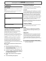
Installation
Before you start your installation, please complete the details
BELOW.
If your customer has a problem relating to your installation
they will be able to contact you easily.
Prior to installation, ensure that the local distribution
conditions (nature of the gas and gas pressure) and the
adjustment of the appliance are compatible.
This appliance shall be installed in accordance with the
regulations in force and only in a well ventilated space. Read
the instructions before installing or using this appliance.
the regulations and standards are as follows:
In your own interest and that of safety, it is law that all
gas appliances be installed by competent persons. Gas
Safe registered installers undertake to work to safe and
satisfactory standards. Failure to install the appliance
correctly could invalidate any warranty or liability claims and
lead to prosecution.
The cooker must be installed in accordance with:
This appliance is not connected to a combustion products
evacuation device. Particular attention shall be given to the
relevant requirements regarding ventilation.
The room containing the cooker should have an air supply in
accordance with BS 5440 Part 2 : 2000. All rooms require an
openable window or equivalent, while some rooms require
a permanent vent in addition to the openable window. The
cooker should not be installed in a bedsitting room with
volume less than 20m³. If it is installed in a room of volume
less than 5m³ an air vent of effective area 100cm² is required;
if it is installed in a room of volume between 5m³ and 10m³,
an air vent of effective area 50cm² is required; while if the
volume exceeds 11m³, no air vent is required.
If there are other fuel burning appliances in the same room,
BS 5440 Part 2 : 2000 should be consulted to determine the
requisite air vent requirements.
The cooker may be installed in a kitchen/kitchen diner but
NOT in a room containing a bath or shower.
All models are supplied set for use on group H natural gas.
A conversion kit for LP gas is included with the appliance.
See the instructions that are supplied with the conversion
kit. After converting the appliance please attach the Gas
Conversion sticker over the appropriate area of the data
badge, this will identify the gas type the appliance is now set
for.

16
If the cooker is to be supplied with gas
through a flexible hose, a stability bracket
or chain must be fitted.
ArtNo.020-0013 Stability bracket
but are
available at most builders’ merchants.
ArtNo.020-0014 Gas pressure tester
Must be in accordance with the
relevant standards.
ArtNo.020-0015 Flexible gas hose
(for electrical checks)
ArtNo.020-0016 Multimeter
1. Electric drill
2. Masonry drill bit (only required if fitting the cooker on a
stone or concrete floor)
3. Wall plugs (only required if fitting the cooker on a stone
or concrete floor)
4. Steel tape measure
5. Cross head screwdriver
6. Flat head screwdriver
7. 4mm & 3mm Allen keys
8. Spirit level
9. Pencil
10. Adjustable spanner
11. Screws for fitting stability bracket
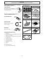
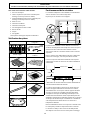
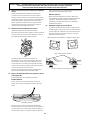
Checking the parts
4 pan supports Levelling tool and Allen keys
ArtNo.110-0002 110 pan supports
ArtNo.000-0002 Classic tools
Grill pan and trivet
3 flat oven shelves and 1 drop
shelf
ArtNo.000-0003 Slide out grill pan
ArtNo.324-0002 Oven shelf
Handyrack Roasting tin
ArtNo.324-0003 Handyrack
ArtNo.324-0004 Roasting tin
Plinth Griddle
ArtNo.000-0008 Griddle
Wok cradle
ArtNo.000-0009 Wok ring, cast

17
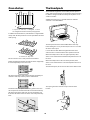
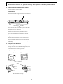
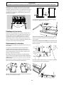
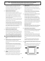
The diagrams below show the minimum recommended
distance from the cooker to nearby surfaces.
The cooker should not be placed on a base.
ArtNo.110-0035 110DF Prof+ min spacings
The hotplate surround should be level with, or above,
any adjacent work surface. A gap of 75mm should be left
between each side of the cooker the hotplate level
and any adjacent vertical surface.
For non-combustible surfaces (such as unpainted metal or
ceramic tiles) this can be reduced to 25mm.
A minimum space of 650mm is required between the top of
the hotplate and a horizontal combustible surface.
ArtNo.110-0003 - Min positions above cooker
*Any cooker hood should be installed in accordance with the
hood manufacturer’s instructions.
Surfaces of furniture and walls at the sides and rear of the
appliance should be heat, splash and steam resistant. Certain
types of vinyl or laminate kitchen furniture are particularly
prone to heat damage and discolouration. We cannot accept
responsibility for damage caused by normal use of the
cooker to any material that de-laminates or discolours at
temperatures less than 65°C above room temperature.
For safety reasons curtains must not be fitted immediately
behind the cooker.
We recommend a gap of 1110mm between units to allow
for moving the cooker. Do not box the cooker in; it must
be possible to move the cooker in and out for cleaning and
servicing.
A clearance of 130mm is required if the cooker is near a
corner of the kitchen to allow the oven doors to open. The
actual opening of the doors is slightly less but this allows for
some protection of your hand as you open the door.
ArtNo.110-0005 110 door clearances
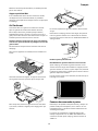
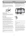
Do not take any packaging off the cooker until it is directly
in front of the place it is to be installed (unless it will not
fit through a door in its outer packaging). Cut the banding
straps and lift the cardboard box off the cooker, leaving
the cooker standing on the base packaging. See the loose
unpacking sheet.
We recommend two people manoeuvre the cooker. Ensure
that the floor covering is firmly fixed, or removed to prevent
it being disturbed when moving the cooker around. You will
need the levelling tool.
From the back tilt the cooker forward and remove the rear
half of the polystyrene base pack.
ArtNo.010-0001 Removing the packaging
Repeat from the front and remove the front half of the poly
base. Pull the drawer out to its furthest point.
ArtNo.340-0002 110 removing the drawer

18
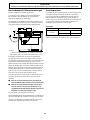
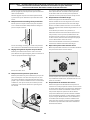
Fit the levelling tool on the rectangular adjuster as shown
below.
ArtNo.010-0008 Lowering the front rollers
LOWER THE FRONT ROLLER by doing 14 complete (360°) turns
clockwise. (This means turning and removing the levelling
tool 56 times).
Now LOWER THE TWO REAR ROLLERS.
First fit the levelling tool on the hexagonal adjusting nut as
shown below.
ArtNo.010-0002 Rear roller nut
Make 10 complete (360°) turns clockwise. (This means turning
and removing the levelling tool 20 times).
ArtNo.010-0003 Lowering the rear rollers
x10
Make sure you lower BOTH REAR ROLLERS. There are two
adjusting nuts, one for each roller, at both the front bottom
corners of the cooker.
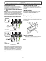
Unfold the rear edge of pack base tray. Carefully push the
cooker backwards out of the base pack. Push the cooker close
to its final position, leaving just enough space to get behind
it.
ArtNo.010-0009 Pushing the cooker
If the appliance is to be converted to LP gas do the
conversion at this point. See the conversion section of these
instructions.
You are recommended to use a spirit level on a shelf in one of
the ovens to check for level.
Place the cooker in its intended position taking care not to
twist it within the gap between the kitchen units as damage
may occur to the cooker or the units.
The rollers can be adjusted to level the cooker. To adjust the
height of the rear of the cooker use the levelling tool supplied
to turn the adjusting nuts at the front bottom corners of the
cooker.
Adjust the height of the front roller to level the cooker. Turn
clockwise to raise the cooker and anticlockwise to lower.
When you are satisfied with the height and level raise the
front of the cooker by one turn of the front roller adjuster.
Screw down the front feet to meet the floor. Screw the front
roller adjuster anticlockwise to raise the front roller so that
the front of the cooker is supported on the feet, not the front
roller, to prevent accidental movement of the cooker.
Leave the levelling tool on the adjuster with the handle of the
tool facing the rear of the cooker, so that the customer can
use it if they wish to move the cooker.
Replace the drawer by locating on side runners and push in.
La page est en cours de chargement...
La page est en cours de chargement...
La page est en cours de chargement...
La page est en cours de chargement...
La page est en cours de chargement...
La page est en cours de chargement...
La page est en cours de chargement...
La page est en cours de chargement...
La page est en cours de chargement...
La page est en cours de chargement...
La page est en cours de chargement...
La page est en cours de chargement...
La page est en cours de chargement...
La page est en cours de chargement...
La page est en cours de chargement...
La page est en cours de chargement...
La page est en cours de chargement...
La page est en cours de chargement...
La page est en cours de chargement...
La page est en cours de chargement...
La page est en cours de chargement...
La page est en cours de chargement...
La page est en cours de chargement...
La page est en cours de chargement...
La page est en cours de chargement...
La page est en cours de chargement...
La page est en cours de chargement...
La page est en cours de chargement...
La page est en cours de chargement...
La page est en cours de chargement...
La page est en cours de chargement...
La page est en cours de chargement...
La page est en cours de chargement...
La page est en cours de chargement...
La page est en cours de chargement...
La page est en cours de chargement...
La page est en cours de chargement...
La page est en cours de chargement...
La page est en cours de chargement...
La page est en cours de chargement...
-
 1
1
-
 2
2
-
 3
3
-
 4
4
-
 5
5
-
 6
6
-
 7
7
-
 8
8
-
 9
9
-
 10
10
-
 11
11
-
 12
12
-
 13
13
-
 14
14
-
 15
15
-
 16
16
-
 17
17
-
 18
18
-
 19
19
-
 20
20
-
 21
21
-
 22
22
-
 23
23
-
 24
24
-
 25
25
-
 26
26
-
 27
27
-
 28
28
-
 29
29
-
 30
30
-
 31
31
-
 32
32
-
 33
33
-
 34
34
-
 35
35
-
 36
36
-
 37
37
-
 38
38
-
 39
39
-
 40
40
-
 41
41
-
 42
42
-
 43
43
-
 44
44
-
 45
45
-
 46
46
-
 47
47
-
 48
48
-
 49
49
-
 50
50
-
 51
51
-
 52
52
-
 53
53
-
 54
54
-
 55
55
-
 56
56
-
 57
57
-
 58
58
-
 59
59
-
 60
60


Falcon Professional+ 110 User Manual & Installation & Service Instructions
- Catégorie
- Fours
- Taper
- User Manual & Installation & Service Instructions
- Ce manuel convient également à
dans d''autres langues
- English: Falcon Professional+ 110
Documents connexes
-
Falcon KCH110DFBLCEU Instructions for Use and Installation
-
-
-
-
-
-
-
-
-
Falcon PROFESSIONAL+ 90 INDUCTION Le manuel du propriétaire
Autres documents
-
AGA MASTERCHEF DELUXE 110 MIX Le manuel du propriétaire
-
Ateca AT265KS134 Fiche technique
-
La Cornue C1VN LP Conversion Instructions
-
KIC KFS 903 BL Mode d'emploi
-
-
Belling 600DIS-T2 Le manuel du propriétaire
-
AGA Masterchef XL 110 Dual Fuel Le manuel du propriétaire
-
-
-