NOMA 052-4345-2 Manuel utilisateur
- Catégorie
- Ventilateurs ménagers
- Taper
- Manuel utilisateur
Ce manuel convient également à

Scandinavian Ceiling Fan
model nos. : 052-4345-2/052-6934-8
Instruction Manual
Toll-free: 1-866-827-4985
IMPORTANT: Please read and understand this manual before any assembly.
Before beginning assembly of product, make sure all parts are present.
Compare parts with exploded view. If any part is missing, or if you have any
questions, contact customer service at 1-866-827-4985 (toll-free).
V5. 2016

Table of Contents
Technical Data
Important Safety Instructions
Parts List
Parts Locations
Before Installation
Installation
Operation
Care and Maintenance
Troubleshooting
Warranty
2
2
3
4
5
6
8
14
16
16
18
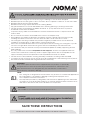
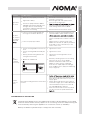
Technical Data
Table of Contents
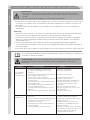
Operating voltage: 120 V/60 Hz
Power consumption: Fan only: 45 W (Maximum)
Bulbs: One E12 candelabra-base bulb (60 W maximum)

WARNING!
or circuit breaker box before installing, servicing or cleaning.
WARNING!
WARNING!
WARNING!
NOTE:
DO NOT use the ceiling fan if it shows any sign of damage or if it has been dropped.
DO NOT expose the ceiling fan to rain or moisture. Do not operate it outdoors or with wet hands.
DO NOT operate the fan without blades.
DO NOT insert foreign objects between the rotating blades.
Pay special attention to the fan and blades when cleaning, painting or working near the fan.
To prevent injury, make sure the blades are not bent and that there are no objects within the
rotation area.
Do not reverse the rotation until blades have come to a complete stop.
The ceiling fan must be grounded as a precaution against possible electric shock. Electrical
installation should be done or approved by a licensed electrician.
Follow the recommended instructions for the proper method of wiring your ceiling fan. If you do
not know enough about electrical wiring, have the fan installed by a licensed electrician.
The outlet box and joist must be securely mounted and capable of reliably supporting at least
35 lb (15.9 kg).
Use only outlet boxes marked “Acceptable for Fan Support” and use the supplied outlet box
screws. Most outlet boxes commonly used to support light fixtures are not acceptable for fan
support and may need to be replaced. Consult a qualified electrician if in doubt.
The fan must not be installed in a ceiling thermally insulated to a value greater than R40.
To reduce the risk of electric shock, this fan must be installed with a wall-isolating control/switch.
All screws must be checked and re-tightened where necessary.
Only use the parts and accessories supplied with this product, or specifically
designated for use with this product by the manufacturer. Substitution with
parts and accessories not designated by the manufacturer could result in
personal injury or property damage.
This ceiling fan is designed for household use only and not for commercial applications.
No responsibility is accepted for damage resulting from improper use or
non-compliance with the instructions.
The important precautions, safeguards, and instructions appearing in this manual are
not meant to cover all possible situations. It must be understood that common sense
and caution are factors that cannot be built into the product.
Not suitable for use with SOLID-STATE speed controls.
SAVE THESE INSTRUCTIONS
IMPORTANT: RETAIN FOR FUTURE REFERENCE, AND READ CAREFULLY.
Important Safety Instructions
The fan must be mounted with the blades at least 6’ 11” (2.1 m) above the floor to prevent
accidental contact with the blades.
All installation should be conducted in accordance with the national and local wiring codes,
including fire-rated construction. Use the national codes if local codes do not exist.
circuit breaker box before installing, servicing, or cleaning.

Toll-free: 1-866-827-4985 · model nos. 052-4345-2/052-6934-8
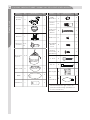
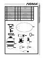
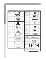
Parts List
Mounting
Bracket
Canopy
A
Receiver
L
Downrod
Assembly
B, C,
D
Motor with
Light Kit
F, G
1
Glass Shade
Blade
Blade Arm
Blade
Decoration
Remote
Control
H
I
J
K
M
4
4
Wood Screw
with Flat
Washer
Blade Screw
Extra Blade
Bracket
Screw
Mouting
Screw with
Split Washer
Balancing Kit
2
13
1
1
2
N
N
Notes:
Parts# N listed in the right column are
packed in hardware bag. (Hardware not
shown to actual size.)
Name No. Illustration Qty. Name No. Illustration Qty.
1
1
1
1
1
4
O
N
N
P
Bulb
(E12 X 60 W)
1
E
1
1
N
N
1
“J” Hook
Zip Tie

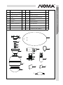
Parts Locations
A
B
C
E
F
G
H
J
K
L
M
N
O
No. Description Qty.
A Mounting Bracket 1
B Nylon Ball 1
C Downrod 1
D Pin 1
E Canopy 1
F Motor Housing 1
G Light Kit 1
H Glass Shade 1
D
No. Description Qty.
I Blade 4
J Blade Arm 4
K Blade Decoration 4
L Receiver 1
M Remote Control 1
N Parts Pack 1
O Balance Pack 1
P Bulb (E12 X 60 W) 1
I
P

1 x cross-head
screwdriver
1 x wrench
1 x stepladder
1 x wire stripper
/pliers
1 x drill
Up to 50' (15 m) 14
50-100' (15-30 m) 12
Toll-free : 1-866-827-4985 · model nos. 052-4345-2/052-6934-8
WARNING!
WARNING!
Do not install or use the ceiling fan if any part is damaged or missing.
WARNING!
or circuit breaker box before installing, servicing or cleaning.
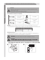
Tools Needed for Assembly (not supplied):
Materials
Unpacking Instructions
Wire Length Wire Size (A.W.G.)
Read each step carefully before beginning any installation and make sure you
understand each step.
Keep children and pets away during installation.
Keep fingers away from the places where they can be pinched or injured.
Wiring, outlet box and box connectors must be of the type required by the local code.
The minimum wire should be a three-conductor (two-wire with ground) of the following sizes:
Place all parts from the box on a working space in a cleared area.
1 x flat screwdriver
Unpack and inspect carefully to make sure all parts are included and not damaged (fig. 1).
shock (fig. 2).
Before Installation

Before Installation
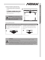
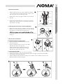
Choosing a Location for the Ceiling Fan
CAUTION! If there is light fixture at your
chosen location, remove the light
fixture first. Before removal, ensure to
fuse or circuit breaker box.
Choosing Mounting Styles
WARNING!
The outlet box and joist must be securely mounted and capable of reliably
supporting at least 35 lb (15.9 kg).
To reduce the risk of electric shock, mount the fan only to an outlet box marked
“Acceptable for Fan Support”, and use the supplied outlet box screws. Most outlet
boxes commonly used to support light fixture are not acceptable for fan support
and may need to be replaced. Consult a qualified electrician if in doubt.
Flush-mount installation (for lower ceilings) Drop-mount installation (for normal ceilings)
Choose a location where there is a high
enough ceiling clearance, at least 6’ 11”
(2.1 m) between the floor and the blades
(fig. 3).
located in the centre of the room, or a
minimum of 32” (81.3 cm) from adjacent
walls or obstructions.
This method is recommended if maximum
headroom is required. The ceiling must be
completely horizontal and level (fig. 4).
Follow step 1-9, omitting step 3 in the
manual.
This method is recommended if the ceiling
is sloped or vaulted or if the ceiling is
extra high, requiring a downrod (fig. 5).
Follow steps 1-9, omitting step 2 in the
manual.
6’ 11”(2.1 m)

Installation
Toll-free: 1-866-827-4985 · model nos. 052-4345-2/052-6934-8
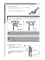
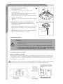
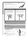
1. Installing Mounting Bracket
WARNING! The mounting bracket must sit firmly against the outlet box. If the
outlet box is recessed, remove the wall board until the mounting bracket comes
into contact with the box. If bracket and/or outlet box are not securely attached,
the fan could wobble or fall.
Before drilling, ensure there are no electrical wires or water pipes behind the
drill spots.
While drilling, we recommend wearing protective goggles and hearing
protection.
CAUTION!
Normal masonry ceiling Wooden ceiling
Remove the four sets of side screws from mounting
bracket and save for future use (fig. 6).
Attach the mounting bracket to the normal masonry
ceiling or wooden ceiling as indicated below.
Securely attach the mounting bracket to
an outlet box marked “Acceptable for Fan
Support”, using the supplied outlet box
screws with lock washers (fig. 7).
Drill two mounting holes in the ceiling joist.
Securely attach the mounting bracket to
the ceiling, using the two sets of long
wood screws with flat washers (fig. 8).
Mounting
bracket
Mounting
bracket
Flat washer
Lock washer
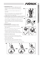
Attach the blade decoration and blade
bracket to the blade (fig. 9).
Apply the blade screws and secure properly
(fig. 9).
2.1 Blade Assembly
Note: This fan includes four dual-finished
blades. Depending on personal
preference, choose the side that best
suits the décor or furniture of your
room.
Blade screw
Blade
Blade decorative
Blade arm
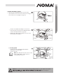
2. Flush-mount Installation (skip step 3)

Installation
Guide all the wires through the base of the canopy
(fig. 10).
Attach the canopy directly to the motor top and
tighten with the three sets of coupling screws with
split washers (fig. 10).
Raise the canopy-motor assembly to the mounting
bracket’s hook and hang by the hole on the canopy.
This allows for hands-free wiring (fig. 11).
mounting bracket’s hook, follow the wiring instructions
(step 4).
Remove the clip and peaked pin from the
downrod (fig. 12).
Remove the ball screw from the nylon ball
and save for future use (fig. 12).
Slide the ball down, without removing it.
The pin is now exposed. Remove the pin
and save for future use (fig. 12).
Place the canopy on top of the motor housing.
Carefully thread the silver cord and all the wires through the downrod assembly.
Insert the pin into the downrod.
2.2Canopy Assembly
Remove three of the six screws and lock washers
(every other one) securing the motor collar to the
top of the fan motor housing (fig. 10).
2.3 Hanging Fan Assembly to Mounting Bracket
3. Drop-mount Installation
3.2 Securing Nylon Ball
3.1 Dismantling Downrod Assembly
Screw
Canopy
Nylon
ball
Downrod
Peaked
pin
Clip
Slide the ball up until the pin fits firmly into the ball. Insert the ball screw into the
ball and tighten properly (fig. 13).
Canopy
Mounting
bracket
Motor collar

15
Installation
Toll-free: 1-866-827-4985 · model nos. 052-4345-2/052-6934-8
Raise the canopy.
Loosen the two downrod set screws on the
coupling (fig. 14).
Insert the downrod into the coupling. Make sure to
align the holes of these two parts.
Install the peaked pin through the aligned holes and
secure it with the clip.
Tighten the two downrod set screws on the coupling
(fig. 14).
Carefully lift the fan assembly and place it on the
mounting bracket.
Rotate the fan assembly until the notch on the nylon
ball fits against the ridge on the mounting bracket
(fig. 15).
With the mounting bracket holding the fan assembly,
follow the wiring instructions (step 4).
All wiring must be in accordance with national and local electrical codes,
including fire-rated construction. If you are unfamiliar with wiring, consult
a qualified electrician.
If you are not sure whether the electrical outlet box and fan are grounded,
contact a licensed electrician for advice. These parts must be grounded!
or circuit breaker box before installing, servicing or cleaning.
3.3 Securing Downrod Assembly
3.4 Hanging Fan Assembly to Mounting Bracket
4. Wiring Instructions
4.1 Installing Receiver Assembly
WARNING!
ScrewClip
Peaked
pin
Nylon ball
Mounting
bracket
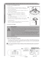
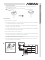
Remote and Receiver Pairing
Codes are set by pushing the location of the dip switches located on the transmitter and
receiver up or down. It is important that the code used for both the remote and receiver
are identical for the two devices to be able to communicate; otherwise the remote will
not be able to control the fan.
If you plan to install more than one fan then each fan will require the remote and receive to
use a unique code, or else one remote will be able to control more than one fan.

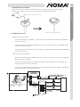
Installing Receiver Assembly
Once the connection has been made, the receiver inserts into the drop rod hanging
bracket. The canopy comes up to cover the receiver and bracket.(fig. 16).
Installation
Between fan and receiver:
· Connect the black wire marked “L” from the fan to the black wire marked “TO MOTOR L”
from the receiver.
· Connect the blue wire marked “FOR LIGHT” from the fan to the blue wire marked “FOR
LIGHT” from the receiver.
· Connect the white wire marked “N” from the fan to the WHITE wire marked “TO MOTOR
N” from the receiver.
Between receiver and mains:
· Connect the black live wire marked “AC IN L” from the receiver to the live wire (typically
black) from the outlet box.
· Connect the white neutral wire marked “AC IN N” from the receiver to the neutral wire
(typically white) from the outlet box.
· Connect the green ground wires from the mounting bracket and nylon ball to the ground
wire (bare or green) from the outlet box.
nylon ball
Downrod
Receiver
Antenna:
DO NOT CUT
OR SPLICE
!
8a
4.2 Making Connections

Installation
Toll-free: 1-866-827-4985 · model nos. 052-4345-2/052-6934-8
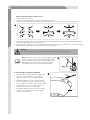
Hold the bare metal leads together and twist until tight.
After all connections are done, turn the splices upward and push them carefully upward through
the mouting bracket into the outlet box.
Spread the wires apart so that the green and white wires are on one side of the outlet box and the
black and blue wires are on the other side of the outlet box.
Warning!
Be sure no bare wire or wire strands are visible after making connections.
While connecting wires, make sure to:
Note: The silver cord is only a safety cable (fig. 19).
You can wrap it over the mounting bracket and
loop it into the hook on the mounting bracket or
alternatively, secure it to the ceiling, using the
provided short wood screw and lock washer.
Hold the fan assembly by the canopy and
raise it to align the holes in the canopy
with the holes in the mounting bracket.
Diagonally apply two sets of side screws
with lock washers to the mounting brcket.
Do not tighten the side screws at this stage.
Hang the two “L” slots of the canopy on
the mounted side screws (fig. 20).
Diagonally apply another two sets of side
screws with lock washers. Tighten all the
side screws properly.
5. Fan Assembly to Mounting Bracket
Match up the wires first.
Insert the twisted ends into a wire connector and turn the wire connector until tight (fig. 18).
Canopy

Installation
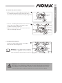
Remove all the blade bracket screws with
split washers from the motor bottom, through
the oval slot on the light kit (fig. 21).
Attach one blade assembly to the motor
bottom and secure with the blade bracket
screws and split washers (fig. 22).
Repeat the above procedures for the other
three blade assemblies.
Install one E12 candelabra bulb (60 W
maximum) into the light
socket (fig. 23).
6. Blade Assembly to Motor
7. Installing Bulb
Note: The dimmer function can not be
used if CFL bulb is used. There is
only ON/OFF function.
Light kit
Blade
screw
Caution! Your fan has an energy-saving wattage limiter. If you replace the bulbs
always below 190 W.
bulb wattage is
23

Installation
Operation
Toll-free: 1-866-827-4985 · model nos. 052-4345-2/052-6934-8
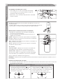
8. Installing Glass Shade
Attach the glass shade to the light kit and
turn clockwise until tight (fig. 24).
Now your ceiling fan is assembled and ready
for use.
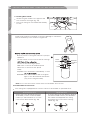
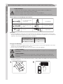
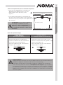
Forward and Reverse Function
Downward air flow Upward air flow
Ceiling fans work best by blowing air
downward (counter-clockwise blade
rotation) in warm weather to cool the
room with a direct breeze (fig. 26).
In winter, having the fan draw air upward
(clockwise blade rotation) will distribute
the warmer air trapped at the ceiling
around the the room without causing
a draft (fig. 27).
· Restore power to ceiling fan and test for proper
operation.
· The fan remote control controls the fan settings:
Note: Do not use the reverse switch when the fan blades are in motion.
HI: Turn on the fan at high speed.
MED: Turn on the fan at medium speed.
LOW: Turn on the fan at low speed.
LIGHT:
ON/OFF: Press and release immediately to turn
DIMMER: Press and hold on to dim or brighten
lights to the desired level and release
(only for the tungsten bulb).
LIGHT
ON/OFF
HI
MED
DIMMER
FAN OFF
LOW
Glass shade
This ceiling fan is equipped with a reverse switch for downward or upward air flow.
9
V
B
a
t
t
e
r
y
Install the 9 V battery (included). To prevent damage to transmitter
remove the battery if not used for long periods .

Operation
Changing Airflow Direction
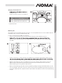
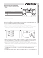
Balancing Kit
Side Description
complete stop.
Slide the reverse switch on the light kit.
Restart the fan.
Left Downward air flow (Forward)
This balancing kit should be used only if there is an unacceptable amount of fan wobble after all
installations are correctly completed (fig. 29).
In case of excessive fan wobble, do as below:
Switch on the fan and choose the fan speed at which the fan wobbles the most.
Switch on the fan to check whether the wobble has increased or decreased. Switch the fan
noting the blade on which the greatest improvement is achieved.
Replace the balancing clip on the blade that shows the greatest improvement. Move the
balancing clip inward and outward, and operate the fan to find the position where the
balancing clip gives the greatest improvement.
Remove the balancing clip and secure the balancing weight (using a provided sticker) on the
top of the blade, along the centre line near the point where the balancing clip was positioned.
If the fan wobble persists, repeat the above procedures and add a second (or more) balancing
weight.
Right Upward air flow (Reverse)
Reverse
switch
balancing clip, halfway between the blade bracket and the blade tip of the trailing edge
(fig. 30).
Blade
Blade
arm

Toll-free: 1-866-827-4985 · model nos. 052-4345-2/052-6934-8
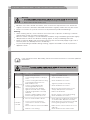
Warning!
Cleaning
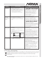
Problem
Possible reason
Solution
Care and MaintenanceTroubleshooting
or circuit breaker box before installing, servicing or cleaning.
Never clean the fan while in use!
Because of the fan’s natural movement, some connections may become loose. Check the
support connections, brackets and blade attachments regularly. Make sure they are secure.
There is no need to oil your fan. The motor has permanently-lubricated bearings.
If the ceiling fan works abnormally, follow the instructions below or consult a qualified
electrician.
WARNING!
main fuse or circuit breaker box before servicing.
Fan is noisy
during
operation
Blade screws are loose.
The mounting bracket or canopy is
loose.
Screws securing decorative housing
to mounting bracket are loose.
Glass shade is loose.
Screws securing downrod to
mounting bracket are loose.
Wire connectors are vibrating
against the inside of the canopy.
Light kit or light bulb is not firmly
attached.
Canopy is rattling against ceiling.
Motor housing screws are loose.
Tighten the blade screws.
Check and fasten the screws.
Check and fasten the screws.
Tighten by hand, as necessary.
Check and fasten the screws.
Disconnect power at fuse box, loosen
canopy and reposition connectors.
Remove and reattach.
Be sure canopy is not touching ceiling.
Check and fasten the screws.
Check main fuse and branch circuit fuses
or circuit breaker. Repair as necessary.
Check all the wire connections to fan and
housing wiring. Repair as necessary.
Make sure the reverse swith is set to one
side only.
Check and ensure the remote works.
Fuse or circuit breaker is blown.
Loose or incorrect power line,
connections to the fan or switch
wires.
Reverse switch is stuck in the middle.
Remote is not working.
Fan does
not start
When cleaning the fan, use a soft brush or lint-free cloth to prevent scratching. A vacuum
cleaner brush nozzle can remove heavier dust.
Remove surface smudges or accumulated dirt and dust using a mild detergent and a slightly
dampened cloth. Never use abrasive cleaning agents, as they will damage the finish.
Clean wood finish blades with a furniture polishing cloth. Occasionally apply a light coat of
furniture polish for added protection and beauty.
To prevent bending the blades during cleaning, support the blades so that no pressure is
applied to them.

Troubleshooting
Problem Possible reason
Solution
Light does
not work
Wires are not properly connected.
Light bulb is faulty.
This fan is equipped with a 190 W
LIMITER that will automatically turn
the light o if the total wattage
exceeds the maximum wattage level.
Remote is not working.
Fan is in reverse mode (blades are
moving in a clockwise direction).
Fan is not properly located.
Screws securing blades to motor are
losse.
Screws securing blade assembly are
loose.
Canopy and mounting bracket are
not tightened securely.
Blades are unbalanced.
Non-match coding between remote and
receiver.
Ensure wire connector in the switch
housing is connected.
Remove light bulb and replace with a
new one of the same type.
with lower wattage bulbs so that the
total wattage will be below 190 W.
Check and ensure the remote works.
Counter-clockwise (forward) direction is
recommended in warm weather. Switch
to stop. Use the eraser end of a pencil to
set the forward/reverse switch to the left
side.
Adjust the fan so that the ends of the
blades have at least 12” (30 cm) clearance
from walls or other obstructions, in the
centre of the room.
Tighten the screws.
Tighten the screws.
Tighten the mounting bracket to the
outlet box.
Check by selecting a point on the ceiling
above the tip of one of the blades.
Measure this distance and ensure all
blades are same (fig. 31). If all blade
levels are not equal, adjust accordingly.
If fan woddle persists, apply the balancing
kit (see page 15).
fuse or circuit breaker box. Wait for at
least 10 seconds and switch on the power
supply again.
Within 30 seconds after power supply is
switched on again, press and hold buttons
1 and 3 simultaneously for five seconds.
The red LED indicator flashers.
Now the remote and receiver are paired.
The fan runs at low speed and with the
Fan does
not seem to
provide the
expected
Fan
wobbles
or shakes
excessively
Remote
does not
work
Used electrical appliances are recyclable and should not be discarded in your regular
domestic waste. Please actively support us in conserving resources and protecting the
environment by returning this appliance to a collection centre (if available).
Battery reclamation (please keep to comply with the local law).
ENVIRONMENTAL PROTECTION

Toll-free: 1-866-827-4985 · model nos. 052-4345-2/052-6934-8
Warranty
This Noma product carries a limited ten (10) year warranty against defects in the motor, and a one (1) year
warranty against defects in workmanship and materials. Noma Canada agrees to replace the defective
product free of charge within the stated warranty period, when returned by the original purchaser with proof
of purchase. This product is not guaranteed against wear or breakage due to misuse and/or abuse.
Made in China
Imported by
Noma Canada, Toronto, Canada M4S 2B8
Subject to the conditions and limitations described below, this product, if returned to us with proof of
purchase within the stated warranty period and if covered under this warranty, will be repaired or
replaced (with the same model, or one of equal value or specification), at our option. We will bear the
cost of any repair or replacement and any costs of labor relating thereto.
These warranties are subject to the following conditions and limitations:
a) A bill of sale verifying the purchase and purchase date must be provided;
b) This warranty will not apply to any product or part thereof which is worn or broken or which has
become inoperative due to abuse, misuse, accidental damage, neglect or lack of proper installation,
operation or maintenance (as outlined in the applicable owner’s manual or operating instructions)
or which is being used for industrial, professional, commercial or rental purposes;
c) This warranty will not apply to normal wear and tear or to expendable parts or accessories that
may be supplied with the product that are expected to become inoperative or unusable after a
reasonable period of use;
d) This warranty will not apply to routine maintenance and consumable items such as, but not limited
to, fuel, lubricants, vacuum bags, blades, belts, sandpaper, bits, fluids, tune-ups or adjustments;
e) This warranty will not apply where damage is caused by repairs made or attempted by others
(i.e. persons not authorized by the manufacturer);
f) This warranty will not apply to any product that was sold to the original purchaser as a
reconditioned or refurbished product (unless otherwise specified in writing);
g) This warranty will not apply to any product or part thereof if any part from another manufacturer
is installed therein or any repairs or alterations have been made or attempted by unauthorized
persons;
h) This warranty will not apply to normal deterioration of the exterior finish, such as, but not limited
to, scratches, dents, paint chips, or to any corrosion or discoloring by heat, abrasive and chemical
cleaners; and
i) This warranty will not apply to component parts sold by and identified as the product of another
company, which shall be covered under the product manufacturer’s warranty, if any.
Additional Limitations
This warranty applies only to the original purchaser and may not be transferred. Neither the retailer nor
the manufacturer shall be liable for any other expense, loss or damage, including, without limitation,
any indirect, incidental, consequential or exemplary damages arising in connection with the sale, use or
inability to use this product.
Notice to Consumer
This warranty gives you specific legal rights, and you may have other rights, which may vary from
province to province. The provisions contained in this warranty are not intended to limit, modify, take
away from, disclaim or exclude any statutory warranties set forth in any applicable provincial or
federal legislation

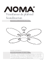
Ventilateur de plafond
Scandinavian
Numéro sans frais : 1 866 827-4985
Nos de modèles : 052-4345-2/052-6934-8
Guide d’utilisation
IMPORTANT : Veuillez lire et bien comprendre ce guide avant de procéder à
l’assemblage. Avant de procéder à l’assemblage du produit, assurez-vous
que toutes les pièces sont présentes. Comparez les pièces à la vue éclatée.
S’il manque des pièces, ou si vous avez des questions, communiquez avec le
service à la clientèle en composant le 1 866 827-4985.
V5. 2016

Table des matières
Données techniques
Consignes de sécurité importantes
Liste des pièces
Emplacements des pièces
Avant l’installation
Installation
Fonctionnement
Entretien
Dépannage
Garantie
2
2
3
4
5
6
8
14
16
16
18
Données techniques
Table des matières
Tension de fonctionnement : 120 V/60 Hz
Consommation électrique : 45 W (max.) pour le ventilateur seulement
Ampoules : une ampoule E12 à petit culot (60 W max.)
La page charge ...
La page charge ...
La page charge ...
La page charge ...
La page charge ...
La page charge ...
La page charge ...
La page charge ...
La page charge ...
La page charge ...
La page charge ...
La page charge ...
La page charge ...
La page charge ...
La page charge ...
La page charge ...
-
 1
1
-
 2
2
-
 3
3
-
 4
4
-
 5
5
-
 6
6
-
 7
7
-
 8
8
-
 9
9
-
 10
10
-
 11
11
-
 12
12
-
 13
13
-
 14
14
-
 15
15
-
 16
16
-
 17
17
-
 18
18
-
 19
19
-
 20
20
-
 21
21
-
 22
22
-
 23
23
-
 24
24
-
 25
25
-
 26
26
-
 27
27
-
 28
28
-
 29
29
-
 30
30
-
 31
31
-
 32
32
-
 33
33
-
 34
34
-
 35
35
-
 36
36


NOMA 052-4345-2 Manuel utilisateur
- Catégorie
- Ventilateurs ménagers
- Taper
- Manuel utilisateur
- Ce manuel convient également à
dans d''autres langues
- English: NOMA 052-4345-2 User manual
Documents connexes
-
NOMA Bower Indoor Le manuel du propriétaire
-
-
-
-
-
Autres documents
-
 Stile CF0140 Mode d'emploi
-
LIVARNO 359555 Le manuel du propriétaire
-
Progress Lighting P250063-031 Guide d'installation
-
 Kichler Lighting Jade 300030 Manuel utilisateur
-
Kichler 310155SBK Manuel utilisateur
-
Progress Lighting P250000-081 Manuel utilisateur
-
 PROGRESS LIGHTNING P250002-143-30 Mode d'emploi
-
 Kichler Lighting Motu Manuel utilisateur
-
-
Fanimation FP8533PN Le manuel du propriétaire


