Shindaiwa B45_B45LA Manuel utilisateur
- Catégorie
- Coupe-herbe
- Taper
- Manuel utilisateur

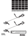
B45
B45/B45LA BRUSHCUTTER
B45LA
WARNING!
SHINDAIWA OWNER'S/OPERATOR'S MANUAL
Minimize the risk of injury to yourself and others!
Read this manual and familiarize yourself with the
contents. Always wear eye and hearing protection
when operating this unit.
X750-015975
X750284-0005
1302D 1048 ES
Printed in Japan

2
Throughout this manual are special
attention statements.
WARNING!
A statement preceded by the
triangular attention symbol and the
word “WARNING” contains informa-
tion that should be acted upon to
prevent serious bodily injury.
CAUTION!
A statement preceded by the word
“CAUTION” contains information
that should be acted upon to prevent
mechanical damage.
IMPORTANT!
A statement preceded by the word
“IMPORTANT” is one that possesses
special signi¿ cance.
NOTE:
A statement preceded by the word “NOTE”
contains information that is handy to know
and may make your job easier.
Attention Statements
IMPORTANT!
The operational procedures described
in this manual are intended to help you
get the most from this unit as well as
to protect you and others from harm.
These procedures are guidelines for
safe operation under most conditions,
and are not intended to replace any
safety rules and/or laws that may be in
force in your area. If you have questions
regarding your shindaiwa power tool,
or if you do not understand something
in this manual, your shindaiwa dealer
will be glad to assist you. You may also
contact YAMABIKO CORPORATION at
the address printed on the back of this
manual.
Introduction
PAGE
The shindaiwa 45-series of hand
power tools has been designed and
built to deliver superior performance
and reliability without compromise to
quality, comfort, or durability.
Shindaiwa high performance engines
represent the leading edge of 2-cycle
engine technology, delivering exception-
ally high power from remarkably low
displacement and weight. As an owner/
operator, you’ll soon discover for your-
self why shindaiwa is simply in a class
by itself!
IMPORTANT!
The information contained in this
manual describes units available at the
time of publication.
YAMABIKO CORPORATION reserves
the right to make changes to products
without prior noti¿ cation, and without
obligation to make alterations to units
previously manufactured.
Contents
Attention Statements .........................2
General Safety Instructions ...............3
Checking Unit Condition ....................3
Safety Labels .....................................5
Unit Description .................................6
Speci¿ cations ....................................6
Assembly ........................................... 7
Mixing Fuel ......................................11
Starting the Engine ..........................12
Stopping the Engine ........................12
Engine Idle Adjustment ....................13
Harness ...........................................13
Using a Brushcutter Blade ...............14
Cutting Grass ..................................15
General Maintenance ......................15
Spark Arrester Installation ...............17
Long Term Storage ..........................18
Blade Sharpening ............................18
Troubleshooting Guide ....................19
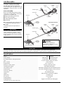
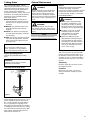
Do not operate this unit
with a blade unless the
unit is equipped with a
Shindaiwa-approved handlebar.
Always wear a harness when
operating this unit with a blade.
A harness is also recommended
when using trimmer line.
Beware of blade thrust. A jammed
blade can cause the brushcutter
to jerk suddenly and may cause
the operator to lose control
of the unit.
Read and follow this
operators manual.
Failure to do so could
result in serious injury.
Wear eye and hearing
protection at all times
during the operation
of this unit.
Keep bystanders
at least 50 feet (15 m)
away during operation.
Beware of thrown or
ricocheted objects.

3
Work Safely
Brushcutters operate at very high
speeds and can do serious damage or
injury if they are misused or abused.
Never allow a person without training or
instruction to operate this unit!
WARNING!
Use Good Judgment
NEVER operate the engine when
transporting the unit.
NEVER operate the engine indoors!
Make sure there is always good ven-
tilation. Fumes from engine exhaust
can cause serious injury or death.
ALWAYS use the proper cutting tool
for the job.
ALWAYS stop the unit immediately
if it suddenly begins to vibrate or
shake. Inspect for broken, missing or
improperly installed parts or attach-
ments.
NEVER extend trimming line beyond
the length speci¿ ed for your unit.
ALWAYS keep the unit as clean as
practical. Keep it free of loose
vegetation, mud, etc.
ALWAYS hold the unit ¿ rmly with
both hands when cutting or trimming,
and maintain control at all times.
ALWAYS keep the handles clean.
ALWAYS disconnect the spark plug
wire before performing any
maintenance work.
ALWAYS, if a blade should bind fast
in a cut, shut off the engine imme-
diately. Push the branch or tree to
ease the bind and free the blade.
Stay Alert
You must be physically and mentally ¿ t
to operate this unit safely.
General Safety Instructions
WARNING!
Never make unauthorized
attachment installations.
WARNING!
Never operate power equipment of
any kind if you are tired or if you
are under the inÀ uence of alcohol,
drugs, medication or any other
substance that could affect your
ability or judgement.
WARNING!
Minimize the Risk of Fire
NEVER smoke or light ¿ res near
the unit.
ALWAYS stop the engine and allow
it to cool before refueling. Avoid
over¿ lling and wipe off any fuel that
may have spilled.
ALWAYS inspect the unit for fuel
leaks before each use. During each
re¿ ll, check that no fuel leaks from
around the fuel cap and/or fuel tank.
If fuel leaks are evident, stop using
the unit immediately. Fuel leaks must
be repaired before using the unit.
ALWAYS move the unit to a place
well away from a fuel storage area
or other readily À ammable materials
before starting the engine.
NEVER place À ammable material
close to the engine mufÀ er.
Checking Unit Condition
NEVER operate the unit with the cutting
attachment shield or other protective
devices (harness, ignition switch, blade
retention clip, etc.) removed!
WARNING!
A cutting attachment shield or other
protective device is no guarantee
of protection against ricochet. YOU
MUST ALWAYS GUARD AGAINST
FLYING DEBRIS!
Use only authorized shindaiwa parts
and accessories with your shindaiwa
brushcutter. Do not make modi¿ cations
to this unit without the written approval
of YAMABIKO CORPORATION.
ALWAYS make sure the cutting attach-
ment is properly installed and ¿ rmly
tightened before operation.
NEVER use a cracked or warped cutting
attachment. If a properly installed at-
tachment vibrates, replace the attach-
ment with new one and re-check.
ALWAYS stop the engine immediately
and check for damage if you strike a
foreign object or if the unit becomes
tangled. Do not operate with broken or
damaged equipment.
NEVER allow the engine to operate
at high RPM without a load. Doing so
could damage the engine.
NEVER operate a unit with worn or
damaged fasteners or attachment
holders.
NEVER cut with a dull blade. Doing so
will increase the risk of blade thrust and
may also cause equipment damage.

4
50'
FIG2B
FIG1B
The Properly Equipped Operator
Always wear a harness
when operating a unit
equipped with a blade.
Always operate with
both hands ¿ rmly
gripping the unit.
Wear close-¿ tting clothing to protect
legs and arms. Gloves offer added
protection and are strongly recom-
mended. Do not wear clothing or
jewelry that could get caught in
machinery or underbrush. Secure
long hair so that it is above
shoulder level.
NEVER wear shorts!
Wear hearing protection devices and a
broad-brimmed hat or helmet.
Always wear eye protection
such as goggles or safety
glasses to shield against
thrown objects.
When operating with a blade, make sure the
handle is positioned to provide you with
maximum protection from contacting the blade.
Keep away from the rotating
trimmer line or blade at all
times, and never lift a moving
attachment above waist-high.
Wear appropriate footwear (non-
skid boots or shoes): do not wear
open-toed shoes or sandals.
Never work barefooted!
Keep a proper footing and
do not overreach.
Maintain your balance at
all times during operation.
Always make sure the appropriate
cutting attachment shield is correctly
installed and in good condition.
Figure 1
Be Aware of the Working Environment
Avoid long-term
operation in very hot or
very cold weather.
Make sure bystanders or
observers outside the 50-foot
“danger zone” wear eye
protection.
Be extremely
careful of
slippery terrain,
especially
during rainy
weather.
If contact is made with a
hard object, stop the
engine and inspect the
cutting attachment for
damage.
Be constantly alert for objects and debris
that could be thrown either from the rotating
cutting attachment or bounced from a hard
surface.
Reduce the risk of
bystanders being
struck by À ying
debris. Make sure
no one is within 50
feet (15 meters)—
that’s about 16
paces—of an
operating
attachment.
Beware of a coasting blade when
brushcutting. A coasting blade can injure
while it continues to spin after the throttle
trigger is released or after the engine is
stopped.
50
FEET
ALWAYS clear your work area of trash or hidden debris that could be thrown back at you
or toward a bystander. When operating in rocky terrain or near electric wires or fences,
use extreme caution to avoid contacting such items with the cutting attachment.
Figure 2

5
Safety Labels
Figure 3
B45
B45LA
IMPORTANT!
Safety and Operation Information Labels:
Make sure all information labels are
undamaged and readable. Immediately
replace damaged or missing information
labels. New labels are available from your
local authorized shindaiwa dealer.

6
Unit Description
Using the accompanying illustrations
as a guide, familiarize yourself with
this unit and its various components.
Understanding this unit helps ensure top
performance, long service life, and safer
operation.
Throttle Trigger
Gearcase
Brushcutter Blade
Outer Tube
Handlebar
Fuel
Tank
Cylinder
Cover
B45 BRUSHCUTTER
Cutting
Attachment
Shield
Hanger
Figure 4
Stand
Ignition
Switch
Spark
Plug
Model ................................................................................................................
Engine Model....................................................................................................
Dry weight without cutting attachment ..............................................................
Type ..................................................................................................................
Bore x Stroke ....................................................................................................
Displacement ....................................................................................................
Maximum Power Output ...................................................................................
Operating rpm Range .......................................................................................
Transmission Type............................................................................................
Fuel/Oil Ratio ....................................................................................................
Fuel Tank Capacity ...........................................................................................
Carburetion .......................................................................................................
Ignition ..............................................................................................................
Spark Plug ........................................................................................................
Air Cleaner........................................................................................................
Starting Method ................................................................................................
Stopping Method ..............................................................................................
Speci¿ cations
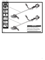
Prior to Assembly
Before assembling this product, please
make sure you have all the components
required for a complete unit:
Ŷ Engine Assembly (Powerhead)
Ŷ Outer Tube Assembly
Ŷ Cutting Attachment Shield
Ŷ Handle Bar
Ŷ Tool kit including: Hex wrenches and
a combination spark plug wrench.
Ŷ Goggles
Carefully inspect all components for
damage.
IMPORTANT!
The terms “left,” “left-hand,” and “LH”:
“right,” “right-hand,” and “RH”; “front”
and “rear” refer to directions as viewed
by the operator during normal operation
of this product.
Speci¿ cations subject to change without notice
IMPORTANT!
International B45/B45LA brushcutter units do not have the spark arrester installed in the mufÀ er. Before placing the
brushcutter in service, check local, state and federal regulations to determine if a spark arrester is required in your area.
B45 B45LA
SM45 Engine SB45LA Engine
17.6 lb./8.0kg 17.8 lb./8.1kg
2-cycle, vertical cylinder, air cooled
40mm x 33mm
41.5.cc/2.58 cu. in.
2.3 hp @ 7500 rpm (r/min)
5500–8500 rpm (r/min)
Automatic centrifugal clutch through bevel gears
50:1 with shindaiwa Premium 2-cycle mixing oil
25.7 oz./760 ml
TK, Diaphragm type
Fully electronic, transistor controlled
Champion CJ8
Foam element
Recoil
Toggle on-off switch, grounding type
Throttle Trigger
Gearcase
Brushcutter Blade
Outer Tube
Handlebar
Fuel
Tank
Cylinder
Cover
B45LA BRUSHCUTTER
Cutting
Attachment
Shield
Hanger
Stand
Ignition
Switch
Spark
Plug
WARNING!
Do not make unauthorized
modi¿ cations or alterations to this
unit or its components.

7
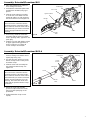
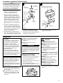
Assembly: Driveshaft/Powerhead B45LA
1. Place the powerhead on a À at
surface, resting on its built-in stand.
(spark plug facing “up”)
2. Use the 4mm hex wrench to loosen
the two clamp screws on the power-
head tube clamp.
3. Slide the outer tube assembly into
the powerhead tube clamp. See
Figure 5-B.
CAUTION!
Do not force the outer tube into the
powerhead! If the outer tube installa-
tion is dif¿ cult, rotate the outer tube or
mainshaft until you feel the mainshaft
splines engage inside the fan cover
housing. The outer tube decal must
align with the powerhead tube clamp
as shown!
4. Rotate the outer tube until the
gearcase output shaft faces down,
away from the spark plug on the
powerhead.
5. Tighten both tube clamp screws
equally.
B45LA Brushcutter
Clamp
Screws
Mainshaft
Powerhead
Tube
Clamp
Outer
Tube
Figure 5B
Decal
Stand
Spark
Plug
04503
Assembly: Driveshaft/Powerhead B45
1. Place the powerhead on a À at sur-
face, resting on its stand.
2. Lubricate the mainshaft splines with
molybdenum disul¿ de (moly) type
grease.
3. Slide the outer tube/cap assembly
on to the fan cover. Make sure the
mainshaft splines are fully engaged
into the clutch drum. See Figure 5-A.
B45 Brushcutter
Powerhead
Fan Cover
Outer
Tube
Figure 5A
Stand
Spark
Plug
Hanger
4. If necessary, rotate the outer tube
assembly until the gearcase output
shaft is pointing down, opposite to the
spark plug.
5. Install four screws with ignition switch
in upper right mounting position as
shown in Figure 5-A. Tighten all
screws evenly to 26-44 in/lbs.
CAUTION!
Do not force the outer tube into the
powerhead! If the outer tube installa-
tion is dif¿ cult, rotate the outer tube or
mainshaft until you feel the mainshaft
splines engage inside the fan cover
housing.
Ignition Switch

8
03510
03509
03511
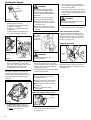
Assembly: Handlebar and Throttle Assembly
Install the Handlebar:
1. Use the 4mm hex wrench to remove
the lower clamp retaining screws
from the handlebar bracket. Seperate
the clamp from the bracket.
2. Position the handle bar on the outer
tube behind the handle positioning
lable. Reassemble the lower clamp to
the handlebar bracket in the reverse
order of disassembly. See Figure 7.
3. Firmly tighten both lower cap
retaining screws.
Install the Throttle Cable:
1. Route the throttle cable through the
cable holder and up and through the
right handlebar grip. See Figures 8
and 9.
2. Using a small screwdriver, pry on
the throttle trigger retaining clip and
partially pull it out of the throttle as-
sembly to allow the throttle trigger to
swing out. See Figure 9.
3. Insert the cable end into the recess in
the trigger and swing the trigger back
into the throttle assembly then push
the trigger retaining clip back into
place. See Figure 9.
4. Install the hip protector with the
throttle cable inside as shown in
Figure 9A.
5. Operate the throttle and check for
smooth operation.
Cable
Holder
Handlebar
Throttle Assembly
Outer Tube
Throttle Cable
Lower Clamp
Retaining Screws
Handlebar
Bracket
Handle Position
Label
Figure 7
Throttle
Lever
Figure 9
Figure 8
Cable End
Trigger
Retaining
Clip
Throttle
Cable
Lower
Clamp
Figure 9A
Hip
Protector
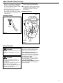
Install the Cutting Attachment Shield
35005
Cutting Attach-
ment Shield
Outer
Tube
Socket-
Head Cap
Screw
Bracket
Clamp
Screw
Retaining
Nut
CAUTION!
Make sure the clamp screw and
retaining nut are securely tightened
before tightening the four socket-
head cap screws.
7. Tighten the four socket-head cap
screws to secure the cutting attach-
ment shield.
Figure 6
1. If using a blade-type cutting
attachment, remove the line cutter
and save for future use.
2. Remove the 6mm clamp screw from
the gearcase clamp.
3. Mount the cutting attachment shield
onto the outer tube assembly us-
ing the longer (40 mm) 6 mm clamp
screw (supplied in the parts package)
¿ nger tight only. See Figure 6.
4. Loosely install the four socket-head
cap screws through the upper bracket
and into the cutting attachment
shield.
5. Firmly tighten the clamp screw.
6. Install the À at washer and retaining
nut onto the clamp screw and tighten
securely.
Flat
Washer
Gearcase
Line Cutter
WARNING!
NEVER operate the B45/B45LA
without the cutting attachment shield
installed and tightly secured!

9
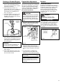
Adjust Throttle Cable Free Play
1. Test the throttle lever for smooth op-
eration. If any stiffness or binding are
noted, the cause must be identi¿ ed
and corrected before the brushcutter
can be placed in service.
2. Test the throttle lever for proper “free
play” of approximately 7mm in the
idle position. See Figure 10. If neces-
sary, adjustments can be made at the
carburetor by:
Ŷ Temporarily moving the adjuster
cover to expose the cable adjuster.
Ŷ Loosening the cable locknut and then
screwing the cable adjuster in or out
until proper free play is achieved.
See Figure 11.
7mm
Free
Play
B45/B45LA Brushcutter
Checking Free Play
Adjusting Free Play
Adjuster
Cover
Cable
Locknut
Cable
Adjuster
Figure 10
Figure 11
03516
Blade Selection
Plastic/Nylon Grass/Weed Blades
may be used where ever the nylon
line head is used. DO NOT use this
blade for heavy weeds or brush.
8 Tooth Weed/Grass Blade is de-
signed for grass, garden debris and
thick weeds. DO NOT use this blade
for brush or heavy woody growth, 19
mm diameter or larger.
80 Tooth Brush Blade is designed
for cutting brush and woody growth
up to 13 mm diameter.
22 Tooth Clearing Blade is designed
for dense thickets and saplings up to
64 mm diameter.
WARNING!
Use only cutting attachments recom-
mended by YAMABIKO CORPORA-
TION.
WARNING!
The type of BLADE used MUST
be matched to the type and size of
material cut.
An improper or dull blade can cause
serious personal injury. Blades
MUST be sharp. Dull blades increase
the chance of kick-out and injury to
yourself and bystanders.

10
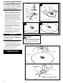
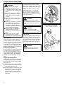
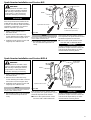
Assembly: Install the Blade
35011
35010
35013
35012
NOTE:
The B45/B45LA is shipped with Holder
“A,” the safety clip, Holder “B,” shaft bolt,
and bolt guard installed. The shaft bolt is a
LEFT-HAND THREAD AND IS REMOVED
IN A CLOCKWISE ROTATION!
1. With the gearcase output shaft
facing up, rotate the gearshaft and
Holder “A” until the hole in Holder “A”
aligns with the matching hole in the
gearcase À ange, and then lock the
holder to the gearcase by insert-
ing the long end of the hex wrench
through both holes. See Figure 12.
2. Remove the shaft bolt, bolt guard and
Holder “B”. See Figure 12.
3. Slide the safety clip off center on the
gearcase shaft. See Figure 12-A.
4. Slide the blade over the safety clip
and onto the À ange on Holder “A”.
See ¿ gure 12-B.
5. Lock the blade on the shaft by center-
ing the safety clip. See Figure 12-C.
6. Install holder “B” on the gearcase
shaft. See Figure 13.
A
B
C
Shaft Bolt
Bolt Guard
Holder “B”
Holder
“A”
Gearcase
Shaft
Slide the saftey clip off-center
Center the safety clipSlip the blade into place
Safety
Clip
Figure 12
Hex
Wrench
Never operate the brushcutter without
the safety clip installed and both hold-
ers tightly secured and À at against
the blade surface!
WARNING!
35015
35014
IMPORTANT!
The machined recess in Holder “B” must
completely surround the safety clip, and
both holders must be À at against the
surface of the blade.
7. Lock Holder “A” to the gearcase by
inserting the long end of the hex
wrench through both holes as done
in step 1 and tighten the shaft bolt
securely with the combination spark
plug wrench. See Figure 14.
8. Remove the hex wrench.
Install Holder
“B”
Saw Blade
Tighten the assembly
Combination Spark
Plug/Screwdriver
Wrench
Hex Wrench
Bolt Guard
Holder “B”
Figure 14
Figure 13
The B45/B45LA should now be
completely assembled.
Blade not shown for clarity

11
35008
35007
Assembly: Installing a Trimmer Head
A
Safety Clip
(not used)
Shaft Bolt
(not used)
Bolt Guard
(not used)
NOTE:
The B45/B45LA is shipped with Holder
“A”, the blade retainer (safety clip), Holder
“B,” shaft bolt, and bolt guard installed.
The shaft bolt is a LEFT-HAND thread.
Remove it by turning CLOCKWISE!
1. Remove the shaft bolt, bolt guard,
Holder “B,” safety clip and the
exsisting cutting attachment.
2. With the gearcase output shaft
facing up, rotate the gearshaft and
Holder “A” until the hole in Holder “A”
aligns with the matching hole in the
gearcase À ange, and then lock the
holder to the gearcase by insert-
ing the long end of the hex wrench
through both holes. See Figure 15-
A.
3. Using the combination spark plug
wrench, remove the shaft bolt, bolt
guard, Holder “B” and the safety clip.
(The bolt guard, shaft bolt and safety
clip are not used with a trimmer
head). See Figure 15-A.
4. Install Holder “B” on the gearcase
shaft. The splined hole on Holder “A”
must engage with the gearcase shaft.
Gearcase
Shaft
Hex Wrench
B
Holder “B”
Holder “A”
Hand-tighten Trimmer Head
(counter-clockwise to install)
Figure 15
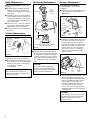
Mixing Fuel
1. Place the unit on a À at, level surface.
2. Clear any dirt or other debris from
around the fuel ¿ ller cap.
3. Remove the fuel cap, and ¿ ll the tank
with clean, fresh fuel.
It is not permitted to ¿ ll fuel above the
shoulder level of fuel tank.
Filling the Fuel Tank
CAUTION!
Some gasolines contain alcohol as
an oxygenate! Oxygenated fuels
may cause increased operating
temperatures. Under certain
conditions, alcohol-based fuels may
also reduce the lubricating qualities
of some mixing oils. Never use any
fuel containing more than 10%
alcohol by volume!
Generic oils and some outboard
motor oils may not be intended for
use in high-performance air cooled
2-cycle engines, and should never be
used in your shindaiwa engine!
CAUTION!
This engine is designed to oper-
ate on a 50:1 mixture consisting of
unleaded gasoline and a premium
2-cycle mixing oil only. Use of
non-approved mixing oils can lead to
excessive maintenance costs and/or
engine damage.
Ŷ Use only fresh, clean unleaded
gasoline with a pump octane rating
of 87 or higher.
Ŷ Mix gasoline with 50:1 shindaiwa
Premium 2-cycle mixing oil or with
an equivalent high quality 2-cycle
mixing oil.
IMPORTANT!
Mix only enough fuel for your immedi-
ate needs! If fuel must be stored longer
than 30 days and shindaiwa One oil with
fuel stabilizer is not used, it should ¿ rst
be treated with a fuel stabilizer such as
STA-BIL™.
WARNING!
Minimize the risk of ¿ re!
Ŷ STOP the engine before refueling.
Ŷ ALWAYS allow the unit to cool
before refueling!
Ŷ Wipe all spilled fuel and move the
unit at least 10 feet (3 meters)
from the fueling point before
restarting!
Ŷ NEVER start or operate this unit if
the carburetor, fuel lines, fuel tank
and/or fuel tank cap are damaged
or leaking.
Ŷ NEVER smoke or light any ¿ res
near the unit or fuels!
Ŷ NEVER place any À ammable
material near the engine mufÀ er!
Ŷ NEVER operate the engine
without the mufÀ er in place and
properly functioning!
5. Using the hex wrench to secure
Holder “A,” install and hand-tighten
the trimmer head (counter-clockwise
to install). See Figure 15-B.
6. Remove the hex wrench from the
gearcase and holder.
Example of 50:1 mixing quantites:
Ŷ 1 gallon of gasoline to 2.6 oz.
mixing oil.
Ŷ 5 liters of gasoline to 100 ml.
mixing oil.
Shoulder Level
4. Reinstall the fuel ¿ ller cap and tighten
¿ rmly.

12
7. If the engine does not continue to
run, repeat the starting procedure as
previously described.
8. When the engine starts, clear excess
fuel from the combustion area by rev-
ving the engine several times with the
throttle lever.
WARNING!
The cutting attachment will rotate as
the engine accelerates!
9. Operating the throttle will automati-
cally disengage the fast-idle setting.
If the engine does not start–
Repeat the appropriate starting pro-
cedures for a hot or cold engine. If the
engine still fails to start, use the follow-
ing procedure for “Starting a Flooded
Engine”. See page 12.
03523
03518
Starting the Engine
1. Set the throttle lever to “fast idle” by
performing the following:
a. Squeeze and hold throttle lever
(toward the handgrip).
b. Depress and hold throttle lever
lock button.
c. While depressing throttle lever
lock, release throttle lock lever.
WARNING!
KEEP WELL CLEAR OF THE
CUTTING ATTACHMENT! THE
CUTTING ATTACHMENT MAY
ROTATE WHEN THE ENGINE IS
STARTED!
Ŷ Place the unit on the ground
during all starting operations.
Ŷ Make sure you have a secure
footing, and keep a ¿ rm grip on
the unit as well.
Ŷ Keep all bystanders and pets
well clear of the trimmer during
starting.
B45/B45LA Throttle Assembly
Throttle
Lever
Lock
Button
IMPORTANT!
The primer system only pushes fuel
through the carburetor and out the
overÀ ow tube. Repeatedly pressing the
primer bulb will not À ood the engine
with fuel.
Choke
Closed
Figure 16
Figure 17
2. Prime the engine by repeatedly
depressing the carburetor primer bulb
while pushing down on the primer
lever (Fig. 17A) until fuel can be seen
À owing through the transparent
overÀ ow tube. See Figure 17.
3. (Cold Engine Only) Choke the
engine by moving the choke lever
up towards the spark plug (choke
is closed). See Figure 18.
Figure 18
Primer
Bulb
OverÀ ow Tube
Primer
Lever
Figure 17A
Choke
Open
Make sure
the cutting
attachment
is clear of
obstructions!
Figure 19
Figure 20
WARNING!
Never start engine from the
operating position!
6. Open the choke by moving the choke
lever down (toward the fuel tank).
See Figure 20.
Stopping the engine
4. While holding the outer tube ¿ rmly
with your left hand, use your right
hand to pull the starter handle slowly
upward until you feel the starter en-
gage. See Figure 19.
5. Start the trimmer by pulling the starter
handle upward rapidly.
CAUTION!
The recoil starter can be easily
damaged by abuse!
Ŷ Always engage the starter before
attempting to crank the engine.
Ŷ Never pull the starter cord to its
full length.
Ŷ Always rewind the starter
cord slowly.
When the engine starts or ¿ res–
Idle the engine brieÀ y before stopping
(about 2 minutes), then push down on
the ignition switch to turn ignition “OFF”.
See Figure 21.
Figure 21
Ignition
OFF

13
Initial carburetor mixture adjustments are:
Slow air screw 0 turn.
Main adjusting screw 2 turns ± 1/4.
Adjustments may vary because of
altitudes and other factors. See your
authorized shindaiwa dealer for correct
adjustments.
Engine Idle Adjustment
The engine must return to idle speed
whenever the throttle lever is released.
Idle speed is adjustable, and must be
set low enough to permit the engine
clutch to disengage the cutting attach-
ment when the throttle is released.
WARNING!
The cutting attachment must NEVER
rotate at engine idle! if the idle speed
cannot be adjusted by the procee-
dure described here, have the unit
inspected at an authorized shindaiwa
dealer.
Figure 23
Idle
Adjusting Screw
Slow Air
Screw
Main Carburetor
Adjustment Screw
1. Place the unit on the ground, then
start the engine and allow it to idle
2-3 minutes until warm.
2. If the attachment rotates when the
engine is at idle, reduce the idle
speed by turning the idle adjustment
screw counter-clockwise. See Figure
23.
3. If a tachometer is available, the
engine idle speed should be ¿ nal
adjusted to 2,750 (±250) rpm (r/min).
Starting a Flooded Engine
1. Disconnect the spark plug lead, and
then use the spark plug wrench to
remove the spark plug (turn counter-
clockwise to remove).
2. If the spark plug is fouled or is
soaked with fuel, clean or replace the
plug as necessary. For spark plug
speci¿ cations and gapping proce-
dure, see page 15.
3. Crank the engine several times with
the choke open and at wide open
throttle to clear excess fuel from the
combustion chamber.
Spark Plug
Turn
counter-
clockwise to
remove
4. Replace the spark plug and tighten it
¿ rmly with the spark plug wrench. If a
torque wrench is available, torque the
spark plug to 148-165 inch-pounds
(170-190 kg/cm).
CAUTION!
Incorrect spark plug installation can
result in serious engine damage!
5. Repeat the starting procedures for a
warm engine.
6. If the engine still fails to start or ¿ re,
refer to the troubleshooting chart at
the end of this manual.
Figure 22
A harness is
required for
use with
brushcutters
Always wear a harness when
operating this unit with a blade.
IMPORTANT!
Adjust the harness so the shoulder pads
rest comfortably on both shoulders and
the cutting path of the cutting attach-
ment is parallel to the ground. Make
sure all hooks and adjustment devices
are secure.
Harness
WARNING!
Figure 24
Brushcutter Harness
A harness provides protection against
blade thrust. In addition, a harness gives
signi¿ cant support and comfort to help
ensure safe and ef¿ cient operation.
When operating a brushcutter, make
sure both the handle and harness are
adjusted to the size of the operator
using the unit.
Idle Speed Adjustment

14
WARNING!
Ŷ Before working with a blade-
equipped unit, always inspect
and clean the area of objects that
could interfere with or damage the
blade.
Ŷ Never use a blade near sidewalks,
fence posts, buildings or other
objects that could cause injury or
damage.
Ŷ Never use a blade for purposes
other than those for which it was
designed.
Ŷ Whenever you strike a hard object
with a blade, always stop the
brushcutter and carefully inspect
the blade for damage. NEVER
OPERATE THE BRUSHCUTTER
WITH A DAMAGED BLADE!
Ŷ A blade-equipped unit must be
equipped with a bicycle-type
handlebar as well as a harness or
strap.
Ŷ Always make sure the cutting
attachment shield is properly
installed before operating the unit.
Blade Thrust
‘Blade thrust’ is a sudden sideways or
backward motion of the brushcutter.
Such motion may occur when the blade
jams or catches on an object such as
a sapling tree or tree stump. BE CON-
STANTLY ALERT FOR BLADE THRUST
AND GUARD AGAINST ITS EFFECTS!
Brushcutter Handlebar
A brushcutter’s handlebar helps prevent
the operator from moving forward, or
the unit moving rearward, thus prevent-
ing inadvertent bodily contact with the
blade. ALWAYS KEEP THE HANDLE-
BAR SECURELY IN PLACE ON THE
UNIT!
Engine Operating Speeds
Operate the engine at full throttle while
cutting. Best fuel ef¿ ciency is obtained
by releasing the throttle when swinging
back after a cut.
Ŷ To prevent possible engine damage,
do not allow the brushcutter to run at
high speeds without a load.
Ŷ Avoid operating the attachment at low
speeds. Doing so can lead to rapid
clutch wear. In addition, slow-speed
operation tends to cause grass and
debris to wrap around the cutting
attachment.
Using A Brushcutter Blade
The blade rotates counter-clockwise.
For best performance and to minimize
being struck by debris, move the blade
from right to left while advancing on your
work.
Position the blade so cuts are made
between the blade’s 7 o’clock and
10 o’clock positions (as viewed from
above). DO NOT cut between the 10
o’clock and 5 o’clock positions (shaded
area). See Figure 25.
WARNING!
When making vertical cuts, never
allow the blade to exceed waist
height.
WARNING!
DO NOT use 2-tooth or NON-
shindaiwa approved 4-tooth cutting
blades with shindaiwa brushcutters.
Vertical cuts
Hold the brushcutter with the blade at a
90° angle to the ground so the blade’s
bottom edge rotates toward the opera-
tor. Move the blade from top to bottom
through the cut, and cut only with the
bottom edge of the blade. See Figure
26.
WARNING!
When cutting wood with a blade,
feed the blade slowly. Never strike or
“slam” a spinning blade against the
wood.
Cut on the left side of the blade.
KEEP YOUR BODY OUTSIDE THE
PATH OF BLADE ROTATION
Figure 26
Figure 25
Ten O’Clock
Seven
O’Clock
OK To Cut
Blade
Rotation
D
O
N
O
T
C
U
T
Five
O’Clock
35032

15
Blades
Keep blades sharp and check blade
condition frequently. If a blade’s
performance changes suddenly, stop the
engine and check the blade for cracks
or other damage. Replace a damaged
blade IMMEDIATELY!
Your shindaiwa B45/B45LA Brush-
cutter may be ¿ tted with one of several
shindaiwa trimmer head models, each
with features for speci¿ c applications
and/or operational requirements.
For proper operation, always refer to the
instructions accompanying the trimmer
head being used. Available trimmer
head styles include:
Ŷ Semi-automatic. Trimmer line is
indexed when the operator taps the
trimmer head on the ground during
operation.
Ŷ Manual. The operator indexes line
manually with the grass trimmer
stopped.
Ŷ Fixed. The operator must stop the
unit and add new lengths of trimmer
line manually.
Ŷ Flail. This device, designed for clear-
ing weeds and light brush, features
three nylon blades attached to the
head by pivots.
CAUTION!
Do not push the rotating line into
trees, wire fences or any material
that could tangle or break line ends.
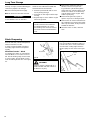
Cutting Grass
CAUTION!
Operation at low rpm can lead to
premature clutch failure.
Trimming and Mowing Grass
Hold the unit so the trimmer head is
angled slightly into the area to be cut. To
ensure maximum trimmer-line service
life, cut only with the tip of the trimmer
line. To prevent grass clippings from
being thrown back towards the operator
or wrapping around the gearcase, swing
the unit’s trimmer head from left to right
while cutting. Keep the trimmer head
horizontal. See Figure 27.
Engine Operating Speeds
Operate at full throttle while cutting
grass.
Figure 27
03529
CUTTING
PATH
RETURN
PATH
WARNING!
Before performing any maintenance,
repair or cleaning work on the unit,
make sure the engine and cutting
attachment are completely stopped.
Disconnect the spark plug wire before
performing service or maintnenance
work.
WARNING!
Non-standard parts may not oper-
ate properly with your unit and may
cause damage and lead to personal
injury.
NOTE:
Using non-standard replacement parts
could invalidate your shindaiwa warranty.
General Maintenance
WARNING!
Ŷ Never repair a damaged blade
by welding, straightening, or by
modifying its shape. An altered
blade may break during operation,
resulting in serious personal injury.
Ŷ DO NOT use 2-tooth or NON-
shindaiwa approved 4-tooth
cutting blades on shindaiwa
trimmers or brushcutters.
Ŷ Blades are not interchange-
able between shindaiwa edgers
and trimmer/brushcutter models.
Operating any unit with a blade or
attachment not approved for that
unit can be hazardous and may
cause serious injury.
MufÀ er
This unit must never be operated with
a faulty or missing mufÀ er. Make sure
the mufÀ er is well secured and in good
condition. A worn or damaged mufÀ er is
a ¿ re hazard and may also cause hear-
ing loss.
Spark Plug
Keep the spark plug and wire connec-
tions tight and clean.
Fasteners
Make sure nuts, bolts, and screws
(except carburetor adjusting screws)
are tight.

16
Air Cleaner
Element
Daily Maintenance
Prior to each work day, perform the
following:
Ŷ Remove all dirt and debris from the
engine, check the cooling ¿ ns and
air cleaner for clogging, and clean as
necessary.
Ŷ Carefully remove any accumulations
of dirt or debris from the mufÀ er and
fuel tank. Dirt build-up in these areas
can lead to engine overheating, ¿ re,
or premature wear.
Ŷ Check for loose or missing screws or
components. Make sure the cutting
attachment is securely fastened.
Ŷ Check the entire unit for leaking fuel
or grease.
10-Hour Maintenance
Clean the spark plug and check the
gap at the electrode.
Every 10 hours of operation (more
frequently in dusty or dirty conditions):
Ŷ Remove the air cleaner element from
the carburetor and clean it thoroughly
with soap and water. Let dry before
reinstalling the element.
See Figure 28.
CAUTION!
Do not operate the unit if the air
cleaner or element is damaged, or if
the element is wet.
10/15-Hour Maintenance
35035
Every 10 to 15 hours of operation:
Ŷ Remove and clean the spark plug.
Adjust the spark plug electrode gap
to 0.024-inch (0.6 mm). If the plug
must be replaced, use only a Cham-
pion CJ8 or equivilent spark plug of
the correct heat range. See Figure
29.
CAUTION!
Before removing the spark plug,
clean the area around the plug to
prevent dirt and debris from getting
into the engine’s internal parts.
0.024-inch
(0.6 mm)
Spark Plug
Turn
counter-
clockwise to
remove
Remove (3)
Screws
Figure 29
Figure 28
Inner
Screen
Outer
Screen
Clip
50-hour Maintenance
Every 50 hours of operation
(more frequently in dusty or dirty
conditions):
Ŷ Remove and clean the cylinder cover
and clean grass and dirt from the
cylinder ¿ ns.
Old
Grease
New
Grease
Gear
Shaft
Collar
Hooked
Wire
Fuel
Filter
Fuel
Line
Figure 31
Figure 30
Ŷ Use a hooked wire to extract the fuel
¿ lter from inside the fuel tank. Re-
move and replace the ¿ lter element.
Before reinstalling the ¿ lter, inspect
the condition of the fuel line. If
damage or deterioration are noted,
the unit should be removed from
service until it can be inspected by a
shindaiwa-trained service technician.
See Figure 31.
CAUTION!
Make sure you do not pierce the fuel
line with the end of the hooked wire,
the line is delicate and can be
damaged easily.
Ŷ Remove the cutting attachment, hold-
er and the gear shaft collar. Remove
the ¿ ller plug from the side of the
gearcase and press new grease into
the gearcase until the old grease has
been pushed out. Use only lithium-
base grease such as shindaiwa
Gearcase Lubricant or equivalent.
See Figure 30.

17
MufÀ er
Spark Arrester Screen
MufÀ er Cowl (secured by 2
socket-head capscrews)
Spark Arrester Installation and Service B45LA
WARNING!
Never operate the unit with a dam-
aged or missing mufÀ er! Operating
with missing or damaged exhaust
components is a ¿ re hazard and
could also damage your hearing.
1. Obtain a spark arrester from a
shindaiwa dealer.
2. Remove the 2 socket-head cap-
screws retaining the mufÀ er cowl and
remove the cowl. See Figure 32-B.
3. Install the spark arrester screen with
a light tap of a mallet to seat.
Socket-head
Capscrews
Figure 32B
IMPORTANT!
If carbon deposits are severe or if no
performance improvement is noted, this
unit should be inspected by an autho-
rized shindaiwa servicing dealer.
NOTE:
The screen is held in place by a press ¿ t
on the mufÀ er exhaust outet.
4. Reinstall the mufÀ er cowl and tighten
the 2 socket-head capscrews se-
curely.
If the engine becomes hard to start or
has low power, the spark arrester screen
should be inspected and cleaned.
Ŷ Remove the spark arrester screen
and clean with a stiff bristle brush.
45038
MufÀ er
Spark Arrester Screen
MufÀ er Cowl (secured by 3
socket-head capscrews)
Spark Arrester Installation and Service B45
WARNING!
Never operate the unit with a dam-
aged or missing mufÀ er! Operating
with missing or damaged exhaust
components is a ¿ re hazard and
could also damage your hearing.
1. Obtain a spark arrester from a
shindaiwa dealer.
2. Remove the 3 socket-head cap-
screws retaining the mufÀ er cowl and
remove the cowl. See Figure 32-A.
3. Install the spark arrester screen with
a light tap of a mallet to seat.
Socket-head
Capscrews
Figure 32A
IMPORTANT!
If carbon deposits are severe or if no
performance improvement is noted, this
unit should be inspected by an autho-
rized shindaiwa servicing dealer.
NOTE:
The screen is held in place by a press ¿ t
on the mufÀ er exhaust outet.
4. Reinstall the mufÀ er cowl and tighten
the 3 socket-head capscrews se-
curely.
If the engine becomes hard to start or
has low power, the spark arrester screen
should be inspected and cleaned.
Ŷ Remove the spark arrester screen
and clean with a stiff bristle brush.
IMPORTANT!
International brushcutter units do not
have the spark arrester installed in the
mufÀ er. Before placing the brushcutter
in service, check local, state and federal
regulations to determine if a spark ar-
rester is required in your area.

18
CAUTION!
Gasoline stored in the carburetor
for extended periods can cause
hard starting, and could also lead to
increased service and maintenance
costs.
Blade Sharpening
Long Term Storage
Whenever the unit will not be used for
30 days or longer, use the following pro-
cedures to prepare it for storage:
Ŷ Clean external parts thoroughly.
Ŷ Drain all the fuel from the fuel tank.
IMPORTANT!
All stored fuels should be stabilized with
a fuel stabilizer such as STA-BIL™.
When the cutting edges of the blade
become dull, they can be resharpened
with a few strokes of a ¿ le.
In order to keep the blade in balance,
all cutting edges must be sharpened
equally.
Shindaiwa Tornado™ Blade
To sharpen the cutters on a shindaiwa
Tornado Blade, use a 7/32-inch round
¿ le. File the leading edge of each tooth
to a razor edge. The top plate of each
tooth should angle back 30°. See Figure
33.
Sharpen only the cutting teeth of a
blade. DO NOT alter the contour of
the blade in any way.
Multiple-tooth Circular Blade
Use a round ¿ le to maintain a radius of
0.04 to 0.06” (1 to 1.5 mm) at the base
of each tooth. Cutting edges must be
offset equally on each side. See Figure
34.
Round
File
30°
Round File
To remove the remaining fuel from the
fuel lines and carburetor and with the
fuel drained from the fuel tank;
1. Prime the primer bulb until no more
fuel is passing through.
2. Start and run the engine until it stops
running.
3. Repeat steps 1 and 2 until the engine
will no longer start.
WARNING!
Ŷ Remove the spark plug and pour
about 1/4 ounce of 2-cycle mix-
ing oil into the cylinder through the
spark plug hole. Slowly pull the recoil
starter 2 or 3 times so oil will evenly
coat the interior of the engine. Rein-
stall the spark plug.
Ŷ Before storing the unit, repair or
replace any worn or damaged parts.
Ŷ Remove the air cleaner element from
the carburetor and clean it thoroughly
with soap and water, let dry and reas-
semble the element.
Ŷ Store the unit in a clean, dust-free
area.
Figure 34
Figure 33

19
Is the engine overheating?
Engine is rough at all speeds.
May aiso have black smoke
and/or unburned fuel at the
exhaust.
Engine is knocking.
Check fuel octane rating;check for presence of
alcohol in the fuel.Refuel as necessary.
See page 11.
Consult with an authorized servicing dealer.
Operator is overworking the unit.
Carburetor mixture is too lean.
Improper fuel ratio.
Fan,fan cover,cylinder fins dirty or
dameged.
Carbon deposits on the piston or in the
muffler.
Clogged air filter.
Loose or damaged spark plug.
Air leakage or clogged fuel line.
Water in the fuel.
Piston seizure.
Faulty carburetor and/or diaphragm.
Overheating condition.
Improper fuel.
Carbon deposits in the combustion
chamber.
Clean or replace the air filter.
Tighten or replace the plug with a Champion
CJ8 or equivalent type spark plug of the correct
heat range.Re-start.
Repair or replace filter and/or fuel line.
Refill with fresh fuel/oil mixture.See Page 11.
Consult with an authorized servicing dealer.
See above.
Shorten trimmer line.Cut at a slower rate.
Consult with an authorized servicing dealer.
Refill with clean fresh unleaded gasoline with a
pump octane of 87 or higher.mixed with
shindaiwa Premium 2-cycle mixing oil at a
50:1 gasoline/oil ratio.
Consult with an authorized servicing dealer.
Consult with an authorized servicing dealer.
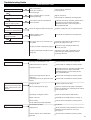
Troubleshooting Guide
ENGINE DOES NOT START
LOW POWER OUTPUT
Does the engine crank?
Faulty recoil starter.
Fluid in the crankcase.
Internal damage.
Consult with an authorized
servicing dealer.
Consult with an authorized servicing dealer.
NO
Good compression?
Loose spark plug.Excess wear on
cylinder,piston,rings.
Tighten and retest.
NO
YES
Does the tank contain fresh
fuel of the proper grade?
Fuel incorrect,stale,or contaminated;
mixture incorrect.
NO
YES
Is fuel visible and moving in
the return line when priming?
NO
Is there spark at the spark
plug wire terminal?
Shorted ignition system.
Faulty ignition unit.
NO
YES
YES
Check the spark plug.
If the plug is wet,excess fuel may be in
the cylinder.
The plug is fouled or improperly gapped.
The plug is damaged internally or of the
wrong size.
Crank the engine with the plug removed,
replace the plug,and re-start.
Clean and re-gap the plug to 0.024 inch
(0.6 mm). Re-start.
Replace the plug with a Champion CJ8 or
equivalent type spark plug of the correct
heat range.Re-start.
YES
What To Check
Possible Cause Remedy
Check for clogged fuel filter and/or vent.
Refill with clean fresh unleaded gasoline with a
pump octane of 87 or higher,mixed with
shindaiwa Premium 2-cycle mixing oil at a
50:1 gasoline/oil ratio.
Replace fuel filter or vent as required.Restart.
Consult with an authorized servicing dealer.

20
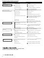
Troubleshooting Guide (continued)
ADDITIONAL PROBLEMS
Poor acceleration.
Symptom Possible Cause
Remedy
Engine stops abruptly.
Ground(stop) wire is disconnected,or
switch is defective.
Overheating due to incorrect spark plug.
Overheated engine.
Test and replace as required.
Replace spark plug with a Champion CJ8 or
equivalent spark plug of the correct heat
range.
Idle engine until cool.
Cutting attachment rotates at
engine idle.
Engine idle too high.
Broken clutch spring or worn clutch
spring boss.
Loose attachment holder.
Set idle:2,750( 250)RPM(r/min).
Replace spring/shoes as required,check idle
speed.
Inspect and re-tighten holders securely.
Excessive vibration.
Warped or damaged cutting attachment.
Loose gearcase.
Bent main shaft/worn or damaged
bushings.
Inspect and replace attachment as required.
Tighten gearcase securely.
Inspect and replace as necessary.
Cutting attachment will not
rotate.
Shaft not installed in powerhead or
gearcase.
Broken shaft.
Damaged gearcase.
Inspect and reinstall as required.
Consult with an authorized servicing dealer.
Engine difficult to shut off.
Clogged fuel filter.
Water in the fuel.
Shorted spark plug or loose terminal.
Ignition failure.
Piston seizure.
Switch turned off.
Fuel tank empty.
Clogged air filter.
Clogged fuel filter.
Lean fuel/air mixture.
Idle speed set too low.
Clean or replace the air filter.
Replace the fuel filter.
Consult with an authorized servicing dealer.
Adjust:2,750( 250)RPM(r/min)
Reset the switch and re-start.
Refuel.See page 11.
Replace filter.
Drain;replace with clean fuel.See page 11.
Clean or replace spark plug with a Champion
CJ8 or equivalent type spark plug of correct
heat range.Tighten the terminal.
Replace the ignition unit.
Consult with an authorized servicing dealer.
Consult with an authorized servicing dealer.
7-2 SUEHIROCHO 1-CHOME, OHME, TOKYO, 198-8760, JAPAN
PHONE: 81-428-32-6118.FAX: 81-428-32-6145
© 2011
-
 1
1
-
 2
2
-
 3
3
-
 4
4
-
 5
5
-
 6
6
-
 7
7
-
 8
8
-
 9
9
-
 10
10
-
 11
11
-
 12
12
-
 13
13
-
 14
14
-
 15
15
-
 16
16
-
 17
17
-
 18
18
-
 19
19
-
 20
20


Shindaiwa B45_B45LA Manuel utilisateur
- Catégorie
- Coupe-herbe
- Taper
- Manuel utilisateur
dans d''autres langues
- English: Shindaiwa B45_B45LA User manual
Documents connexes
-
Shindaiwa T3410X/EVC Manuel utilisateur
-
-
Shindaiwa T2510X/EVC Manuel utilisateur
-
-
-
-
-
-
-
Autres documents
-
Hitachi CG40EAF Le manuel du propriétaire
-
Cub Cadet SS270 Manuel utilisateur
-
Husqvarna 128R Manuel utilisateur
-
 Poulan Pro PP28RJ Manuel utilisateur
-
-
Poulan PPB300 Le manuel du propriétaire
-
-
Ryobi RFT254 Le manuel du propriétaire
-
Craftsman C944.511571 Manuel utilisateur
-
