Maytag MHWC7500YW0 Manuel utilisateur
- Catégorie
- Machines à laver
- Taper
- Manuel utilisateur

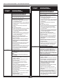
FOR SERVICE TECHNICIAN ONLY - DO NOT REMOVE OR DESTROY
PART NO. W10468733A PAGE 1
IMPORTANT
Electrostatic Discharge (ESD)
Sensitive Electronics
ESD problems are present everywhere. ESD may damage
or weaken the electronic control assembly. The new control
assembly may appear to work well after repair is finished,
but failure may occur at a later date due to ESD stress.
■
Use an anti-static wrist strap. Connect wrist strap to green
ground connection point or unpainted metal in the appliance.
-OR-
Touch your finger repeatedly to a green ground connection point
or unpainted metal in the appliance.
■
Before removing the part from its package, touch the anti-
static bag to a green ground connection point or unpainted
metal in the appliance.
■
Avoid touching electronic parts or terminal contacts; handle
electronic control assembly by edges only.
■
When repackaging failed electronic control assembly in anti-
static bag, observe above instructions.
D
IAGNOSTIC GUIDE
Before servicing, check the following:
• Make sure there is power at the wall outlet.
• Has a household fuse blown or circuit breaker tripped? Time
delay fuse?
•
Are both hot and cold water faucets open and water supply
hoses unobstructed?
• All tests/checks should be made with a VOM or DVM having
a sensitivity of 20,000 ohms per volt DC or greater.
• Check all connections before replacing components. Look for
b
roken or loose wires, failed terminals, or wires not pressed into
connections far enough.
• A potential cause of a control not functioning is corrosion on
connections. Observe connections and check for continuity
with an ohmmeter.
• Connectors: Look at top of connector. Check for broken or loose
wires. Check for wires not pressed into connector far enough to
engage metal barbs.
• Resistance checks must be made with power cord unplugged
from outlet, and with wiring harness or connectors disconnected.
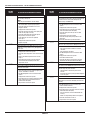
POSSIBLE CAUSE/TEST
PROBLEM NOTE: Possible Cause/Tests must be performed in the sequence shown for each problem.
WON’T POWER UP 1. Check that the washer is plugged into a working outlet and for blown fuses.
(buttons do not respond 2. Check for power going to Central Control Unit (CCU) by listening for a click in the CCU
when pressed) when the washer is plugged in. If no click, replace the CCU.
3. Unplug washer or disconnect power.
4. Check continuity of line cord and line filter.
5. Check harness connections to the CCU.
6. Plug in washer or reconnect power.
7. Check the button/LED assembly by selecting different cycles and changing the modifiers
and options available to confirm that the button/LED assembly is responding.
8. Check the connection of the power cord to the line filter and at the CCU. Check to confirm
that the door closes fully.
WON’T START CYCLE 1. Open and close the door. The door must be opened between consecutive wash cycles.
2. Check the door switch/lock unit using the diagnostics. See Quick Diagnostic Test.
3. If door is locked, drain the washer.
4. Unplug washer or disconnect power.
5. Check the wire harness connections.
6. Plug in washer or reconnect power.
7. Check the button/LED assembly by selecting different cycles and changing the modifiers
and options available to confirm that the button/LED assembly is responding.
TROUBLESHOOTING GUIDE
NOTE: After problem(s) are fixed, please run the diagnostic test to ensure that there are no other issues.

FOR SERVICE TECHNICIAN ONLY - DO NOT REMOVE OR DESTROY
PAGE 2
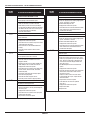
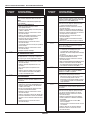
POSSIBLE CAUSE/TEST
PROBLEM NOTE: Possible Cause/Tests must be performed in the sequence shown for each problem.
W
ON’T SHUT OFF 1. Check for a Fault/Error Code on the display.
2. Turn cycle control knob to OFF position.
3. Check the button/LED assembly by selecting different cycles and changing the modifiers
and options available to confirm that the button/LED assembly is responding.
4. Unplug washer or disconnect power.
5. Check that the drain hose and drain pump filter are clear of foreign objects and not plugged.
6. Plug in washer or reconnect power.
7. Check drain pump.
8. Verify CCU operation by running a Quick Diagnostic Test or any cycle.
9. Check knob assembly on the CCU to ensure the direction is properly oriented. See page 12.
CONTROL WON’T 1. Turn cycle control knob to OFF position.
ACCEPT SELECTIONS 2. Drain the washer, and then check that the drain hose and drain pump filter are clear
of foreign objects.
3. Check the button/LED assembly by using the Universal test mode.
4. Unplug washer or disconnect power.
5. Check harness connections.
6. Plug in washer or reconnect power.
7. Verify CCU operation by running a Diagnostic Test or any cycle.
WON’T DISPENSE 1. Verify that the washer is level.
2. Verify that the dispenser drawer is not clogged with detergent.
3. Check water connections to the washer and within the washer. Check for plugged screen
in water source.
4. Check the water supply and the water valve.
5. Unplug washer or disconnect power.
6. Check harness connections.
7. Plug in washer or reconnect power.
8. Verify CCU operation by running a Quick Diagnostic Test or any cycle.
WON’T FILL 1. Check installation. Verify that hot and cold water faucets are open.
2. Check inlet valves.
3. Unplug washer or disconnect power.
4. Check water connections to the washer and within the washer. Make sure water supply
hoses are unobstructed. Check for plugged screen.
5. Plug in washer or reconnect power.
6. Check operation of pressure switch.
7. Check drain pump motor.
8. Verify CCU operation by running a Quick Diagnostic Test or any cycle.
9. Check the steps listed under WON'T DISPENSE.
OVERFILLS 1. Verify that the washer is level.
2. Check pump drain system – this could indicate a failure to drain.
3. Unplug washer or disconnect power.
4. Check operation of pressure switch.
5. Check pressure switch hose.
6. Plug in washer or reconnect power.
7. Verify flow meter operation by blowing air though the part and measuring the resistance.
8. Verify CCU operation by running a Quick Diagnostic Test or any cycle.
DRUM WON’T ROTATE 1. Check drive belt.
2. Check drive motor.
3. Unplug washer or disconnect power.
4. Check wire harness connections.
5. Plug in washer or reconnect power.
6. Perform the Motor Continuity Test.
MOTOR OVERHEATS 1. Check drive motor.
2. Unplug washer or disconnect power.
3. Check wire harness connections.
4. Check drive belt.
5. Plug in washer or reconnect power.
6. Check for obstruction between the spin basket and the outer tub.
T
ROUBLESHOOTING GUIDE
NOTE: After problem(s) are fixed, please run the diagnostic test to ensure that there are no other issues.

FOR SERVICE TECHNICIAN ONLY - DO NOT REMOVE OR DESTROY
PAGE 3
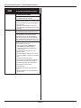
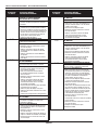
POSSIBLE CAUSE/TEST
PROBLEM NOTE: Possible Cause/Tests must be performed in the sequence shown for each problem.
W
ON’T DRAIN 1. Unplug washer or disconnect power.
2. Check wire harness connections.
3. Check drain pump.
4. Check drain pump motor.
5. Check that the drain hose and drain pump filter are clear of foreign objects.
6. Plug in washer or reconnect power.
7. Verify CCU operation by running a Quick Diagnostic Test or any cycle.
WASHER VIBRATES 1. Remove shipping system.
2. Check installation.
3. Check leveling feet.
INCORRECT WATER 1. Check that the inlet hoses are connected properly.
TEMPERATURE 2. Unplug washer or disconnect power.
3. Check water temperature sensor for an abnormal condition. See the Water Temperature
Sensor section, page 11.
4. Plug in washer or reconnect power.
5. Verify CCU operation by running a Diagnostic Test or any cycle.
DISPLAY FLASHING See Failure/Error Display Codes.
T
ROUBLESHOOTING GUIDE
NOTE: After problem(s) are fixed, please run the diagnostic test to ensure that there are no other issues.
DIAGNOSTIC TEST
The two test modes contain three modes of operation:
Test modes:
■ Universal test mode, with additional user interface test at the beginning
■ Quick test mode
Operation modes:
■ User interface test
■ Automated test
■ Loads test to assist in diagnosing potentially non-electrical issue
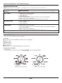
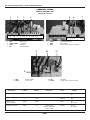
Starting Universal Test Mode
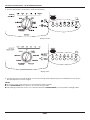
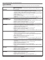
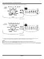
1. Close the door.
2. Rotate the cycle control knob and select the CLEAN WASHER cycle (see illustrations below).
Whirlpool cycle control knob Maytag cycle control knob

FOR SERVICE TECHNICIAN ONLY - DO NOT REMOVE OR DESTROY
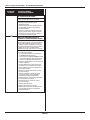
PAGE 4
3. Press CANCEL/DRAIN twice, then press START button twice within 5 seconds (see illustrations below).
Whirlpool model Maytag model
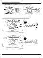
4. Upon release, and after door is locked, all console LED lights will turn ON except the option LED.
Whirlpool model
Maytag model

FOR SERVICE TECHNICIAN ONLY - DO NOT REMOVE OR DESTROY
PAGE 5
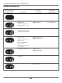
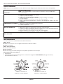
5. Press the option buttons, one at a time, to check the User Interface.
Whirlpool model
Maytag model
6. The following steps are automatically driven, or they can be manually advanced by pressing the Cancel/Drain button twice. See the
Universal Diagnostics Test chart on page 6.
NOTES:
■ To cancel out of this mode, rotate the cycle control knob (this exits the program).
■ Press CANCEL/DRAIN twice to advance to the next step of the procedure.
■ If the starting procedure fails, turn the cycle control knob back to the CLEAN WASHER cycle, then repeat the starting procedure.

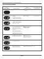
Indication
Factory Test Display Actuators Failure Code
(7-SEGMENT LED) Control Action to be Checked for Failure Mode
OFF Door locks. ■ Door lock system F13
0 (Phase LED rolling) Checks the validity of the ■ Drain system F03, F05, F14, F21,
EEPROM data. ■ EEPROM test F23, F24, F26, F30
Pump turns ON if the water
level is detected to be above
the wash level.
8 All display LEDs are turned on. ■ User Interface F21, F25
UI option LED will be turned
on after options are pushed.
1 Turns on hot inlet valve ■ Hot water inlet valve F01, F21, F23, F24
(about 15 secs.). ■ Cold water inlet valve
■ Bleach inlet valve
Turns on bleach inlet valve
(about 15 secs.).
Turns on cold inlet valve
(about 15 secs.).
Fill by cold water inlet valve
to Level_wash
2 Motor reverse. Runs at normal ■ Reversing relay F06, F07, F21, F27
washing speed (about 15 secs.). ■ Safety relay
■ Motor thermistor
■ Tachometer signal
3 Pump turns ON to drain ■ Drain system F03, F21
the washer.
4 Drive motor to max. speed. ■ Motor speed F06, F07, F21, F27,
■ Tap field relay F28
FOR SERVICE TECHNICIAN ONLY - DO NOT REMOVE OR DESTROY
PAGE 6
U
NIVERSAL DIAGNOSTICS TEST

FOR SERVICE TECHNICIAN ONLY - DO NOT REMOVE OR DESTROY
PAGE 7
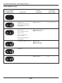
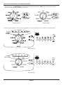
Starting Quick Test Mode
All of the steps below must be done in sequence in order to reach the Diagnostic Test. This exceutes the automatic test but does not run the
u
ser interface test.
1. Close the door.
2. Rotate the cycle control knob and select the CLEAN WASHER cycle (see illustrations below).
NOTES:
Please ensure that current washer status is in PROGRAM (SELECTION) mode. Otherwise, please follow the instructions below to bring it
back to PROGRAM (SELECTION) mode.
PAUSE mode: Press and hold CANCEL/DRAIN button for 3 seconds for reset, then turn cycle control knob to enter PROGRAM mode.
FAILURE mode: Turn cycle control knob to enter PROGRAM mode.
EXECUTION mode: Press and hold CANCEL/DRAIN button for 3 seconds for reset, then turn cycle control knob to enter PROGRAM mode.
STANDBY mode: Press START button or turn cycle control knob to enter PROGRAM mode.
DELAY START mode: Turn cycle control knob to enter PROGRAM mode.
3. Press the START button 4 times within 5 seconds (see illustrations below).
4. The following steps are automatically driven, or they can be manually advanced by pressing the Cancel/Drain button twice. See the
Quick Diagnostics Test chart on page 8.
NOTES:
■ To cancel out of this mode, rotate the cycle control knob (this exits the program).
■ Press CANCEL/DRAIN twice to advance to the next step of the procedure.
■ If the starting procedure fails, turn the cycle control knob back to the CLEAN WASHER cycle, then repeat the starting procedure.
Whirlpool cycle control knob Maytag cycle control knob
Whirlpool model Maytag model

FOR SERVICE TECHNICIAN ONLY - DO NOT REMOVE OR DESTROY
PAGE 8
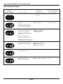
Indication
Factory Test Display Actuators Failure Code
(7-SEGMENT LED) Control Action to be Checked for Failure Mode
OFF Door locks. ■ Door lock system F13
0 (Phase LED rolling) Checks the validity of the ■ Drain system F03, F05, F14, F21,
EEPROM data. ■ EEPROM test F23, F24, F26, F30
Pump turns ON if the water
level is detected to be above
the wash level.
1 Turns on hot inlet valve ■ Hot water inlet valve F01, F21, F23, F24
(about 15 secs.). ■ Cold water inlet valve
■ Bleach inlet valve
Turns on bleach inlet valve
(about 15 secs.).
Turns on cold inlet valve
(about 15 secs.).
Fill by cold water inlet valve
to Level_wash
2 Motor reverse. Runs at normal ■ Reversing relay F06, F07, F21, F27
washing speed (about 15 secs.). ■ Safety relay
■ Motor thermistor
■ Tachometer signal
3 Pump turns ON to drain ■ Drain system F03, F21
the washer.
4 Drive motor to max. speed. ■ Motor speed F06, F07, F21, F27,
■ Tap field relay F28
Q
UICK DIAGNOSTICS TEST

FOR SERVICE TECHNICIAN ONLY - DO NOT REMOVE OR DESTROY
PAGE 9
C
OMPONENT TESTING
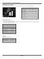
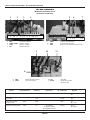
CENTRAL CONTROL UNIT
Connector Location
1
2
34
56 7
1 2 1 2 3 1 2 1 2 3 4 5 6 7
1 2 12 12
1. DP2 Drain Pump
2. VPW3 & VW3 Cold Valve
3. VHF3 Hot Valve
4. M7 Universal Motor
5. SET2 Temperature Sensor
6. DU3 Door Switch
7. PR2 Pressoswitch Input Low Voltage
9 10 11
8
1 2 3 1 2
1 2
21
8. MS2 Motor Supply
9. DLS3 Door Lock
10. IF2 RFI Filter
11. PRS2 Safety Level of Pressoswitch
External Con. ID Electrical Wire
Component of Timer Ratings Resistance Color Signals
RFI Filter IF2 120V Black 1: N
2: L
Motor Supply MS2 1, 2: 1: Blue 1: L
120 2: Black 2: N
Safety Level PRS2 120V Blue 1: L
of Pressoswitch 2: L_safe
Temperature Sensor SET2 5V Refer to the Orange 1: Vcc
Water Temperature 2: V_NTC
Sensor Chart

FOR SERVICE TECHNICIAN ONLY - DO NOT REMOVE OR DESTROY
PAGE 10
External Con. ID Electrical Wire
Component of Timer Ratings Resistance Color Signals
Universal Motor M7 1, 2, 3: 12V Orange 1: SP (Safety Product)
4: 5V 2: RC (Reverse Control)
5: 12V 3: TC (Tapped Field)
6
, 7: 60V 4: PC (Phase Control)
5: –12V
6: T1 (Tacho1)
7: T2 (Tacho2)
Door Lock Device DLS3 1: 120V 1 to 2, Infinity Black 1: L_ref
Interface (PTC 3 tap) 2, 3: 120V 2 to 3, Infinity 2: N_dlock
1 to 3, 1.5 ohm 3: N
Cold Valve, Main Wash, VW3 120V 1 to 2, 970 ohm ±15% Blue 1: N
and Bleach VPW3 1 to 3, 970 ohm ±15% 2: L_ref
3: L_ref
Hot Valve VHF2 120V 1 to 2, 970 ohm ±15% Blue 1: N_vh
2: L_ref
Drain Pump DP2 120V 1 to 2, 28 ohm ±7% Red 1: L_ref
2: N_pump
Door Switch DU3 5V Door Open: Infinity Blue 1: Vcc_ref
Door Close: 0 ohm 2: Vcc_ds
Pressoswitch Input PR2 1: 120V Brown 1: Vcc_levwash
Low Range (classic) 2: 120V 2: Vcc_ovf
User Interface UI4 5V Blue 1: V_gnd
Connection (I2C) 2: V1_clock
3: V1_data
4: V1
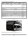
Line Filter
A
C
B
D
A to C = 0 ohm
B to D = 0 ohm
Be sure to perform the Diagnostic Tests before replacing the system components.
It is best to measure load resistances through the wire harness at the control board.

FOR SERVICE TECHNICIAN ONLY - DO NOT REMOVE OR DESTROY
PAGE 11
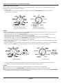
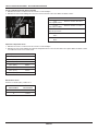
Motor Continuity Test (Connector M7)
1. Unplug washer or disconnect power.
2. Disconnect the wire harness from the motor and measure the resistance of the motor. Use the following table:
Water Temperature Sensor
1. Unplug washer or disconnect power.
2. Disconnect the wire harness from the water temperature sensor and measure the resistance of the sensor. Use the following table.
An abnormal condition is an open circuit.
Water Valves
Nominal resistor (20°C): 970Ω ±15%
10,9,8,7,6,5,4,3,2,1
Pins Results
1 to 5 Normal = approx. 0.2 ohms
High Speed Stator
5 to 10 Normal = approx. 1.1 ohms
Low Speed Stator
6 to 7 Normal = approx. 0 ohms
Protector
3
to 4 Normal = approx. 68 ohms
Tacho
8 to 9 Normal = approx. 0.95 ohms
Rotor
Temperature Results
32°F (0°C) 35,975 k
86°F (30°C) 9,786 k
104°F (40°C) 6,653 k
122°F (50°C) 4,608 k
140°F (60°C) 3,243 k
158°F (71°C) 2,332 k
203°F (96°C) 1,093 k
Supplied Voltage Valve Status
≥ nominal voltage opened
0 closed

FOR SERVICE TECHNICIAN ONLY - DO NOT REMOVE OR DESTROY
PAGE 12
E
LECTRONIC ASSEMBLIES – REMOVAL OR REPLACEMENT
NOTE: Be sure to perform the Diagnostic Tests before replacing the control board.
IMPORTANT: Electrostatic (static electricity) discharge may cause damage to electronic control assemblies. See page 1 for details.
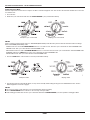
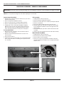
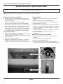
Central Control Unit (CCU):
1. Unplug washer or disconnect power, and turn the cycle control
k
nob to the OFF position.
2. Remove front panel and dispenser drawer.
3. Remove screws that were covered by dispenser drawer.
4. Remove control panel and all connectors from the CCU.
5. Lift tab at left corner of CCU with a flat blade screwdriver.
Slide the CCU to the rear of the washer cabinet until the two
tabs on the back of the CCU align with the keyhole notches
in the control panel. Pull the CCU away from control panel.
To reassemble CCU:
1. Align the two tabs on the back of the CCU with the keyhole
notches in the control panel.
2. Slide the CCU forward until the tab at the rear of the CCU
locks into place.
3. Reconnect wire harness.
4. Verify that the CCU encoder and the cycle control knob are both
at the “off” position before assembling. See the pictures below
as a visual aid.
LED assembly:
1. Unplug washer or disconnect power.
2. Remove front panel and dispenser drawer.
3. Remove the screws that were covered by the dispenser drawer.
4. Remove control panel.
5. Disconnect LED assembly wire harness from the CCU.
6. Along the upper side of the LED assembly there are two tabs;
insert a flat blade screwdriver to release the upper side of the
LED assembly.
7. On the left hand side, press tab to release left side of the LED
assembly.
8. Gently pry up and completely release the entire LED assembly.
Motor Control Unit (MCU):
1. Unplug washer or disconnect power.
2. Disconnect the wire harness from the MCU.
3. Remove drain hose from the MCU.
4. Remove the screw using a flat blade screwdriver. Lift up the
front tab and slide the assembly to the rear. Separate the MCU
from the cover.

FOR SERVICE TECHNICIAN ONLY - DO NOT REMOVE OR DESTROY
PAGE 13
WASHER
DISPLAY EXPLANATION AND RECOMMENDED PROCEDURE
NO WATER DETECTED ENTERING WASHER
OR PRESSURE SWITCH TRIP NOT DETECTED
Water level is not reached within a defined time
in normal wash cycle.
P
ossible Causes/Procedure
I
f there is no water in the washer:
– Make sure that both valves at the water source(s)
are turned on all the way.
– Check for plugged or kinked inlet hoses or plugged
screens in the inlet valves.
– Verify inlet valve operation.
If there is water in the washer:
– Verify drain pump operation.
– Remove hose from pressure switch. Dislodge any
debris buildup in the hose inside the outer tub.
– Verify that the pressure switch hose is in good
condition and properly connected to tub and
pressure switch.
1. Verify there is not a siphon problem.
2. Unplug washer or disconnect power.
3. Verify wire harness connections to inlet valves,
pressure switch, drain pump, and Central Control
Unit (CCU).
4. Check all hoses for possible leaks.
5. Plug in washer or reconnect power.
6. Verify pressure switch operation.
7. Verify CCU operation by running a Quick Diagnostic
Test or any cycle.
LONG DRAIN
If the drain time exceeds 4 minutes, the water valves
turn off.
NOTE:
Rotate the cycle control knob to clear the display.
Possible Causes/Procedure
1. Check the drain hose and make sure it is not
plugged or kinked.
2. Unplug washer or disconnect power.
3. Remove hose from pressure switch. Dislodge any
debris buildup in the hose inside the outer tub.
4. Check the electrical connections at the pump and
make sure the pump is running.
5. Check the drain pump filter for foreign objects.
6. Plug in washer or reconnect power.
7. If the above does not correct the problem,
go to step 8.
8. Unplug washer or disconnect power.
9. Replace the pump.
A
09
A
10
WASHER
DISPLAY EXPLANATION AND RECOMMENDED PROCEDURE
NO WATER DETECTED ENTERING WASHER
OR PRESSURE SWITCH TRIP NOT DETECTED
Water level is not reached within a variable time
(EEPROM parameter) in Whirlpool factory test.
P
ossible Causes/Procedure
I
f there is no water in the washer:
– Make sure that both valves at the water source(s)
are turned on all the way.
– Check for plugged or kinked inlet hoses or plugged
screens in the inlet valves.
– Verify inlet valve operation.
If there is water in the washer:
– Verify drain pump operation.
– Remove hose from pressure switch. Dislodge any
debris buildup in the hose inside the outer tub.
– Verify that the pressure switch hose is in good
condition and properly connected to tub and
pressure switch.
1. Verify there is not a siphon problem.
2. Unplug washer or disconnect power.
3. Verify wire harness connections to inlet valves,
pressure switch, drain pump, and Central Control
Unit (CCU).
4. Check all hoses for possible leaks.
5. Plug in washer or reconnect power.
6. Verify pressure switch operation.
7. Verify CCU operation by running a Quick Diagnostic
Test or any cycle.
OVERFLOW CONDITION
Overflow level has been reached, and lasts for more
than 2 seconds. In an overflow condition, the door
remains locked and the drain pump runs constantly;
after 10 minutes, door will be unlocked in order to cut
off the valves’ power. Then if overflow still occurs, start
pump again.Turn off hot and cold water faucets and
unplug the washer before servicing.
Possible Causes/Procedure
1. Check the drain hose and make sure it is not
plugged or kinked.
2. Unplug washer or disconnect power; if water still
flows into the washer, replace the water valve.
3. Check wire harness connections to the drain pump,
pressure switch, water inlet valve, and Central
Control Unit (CCU).
4. Check/clean drain pump filter of foreign objects.
5. Check for drain pump failure.
6. Check the inlet valve for proper shutoff.
7. Check the pressure switch for proper operation.
8. Remove hose from pressure switch. Dislodge
any debris buildup in the hose inside the outer tub.
Debris inside the hose will not allow the switch to
sense a pressure change.
F
01
F
02
D
ISPLAY FAILURE/ERROR CODES

FOR SERVICE TECHNICIAN ONLY - DO NOT REMOVE OR DESTROY
PAGE 14
WASHER
DISPLAY EXPLANATION AND RECOMMENDED PROCEDURE
LONG DRAIN
If the drain time exceeds 4 minutes, the water valves
turn off. Only in factory test.
N
OTE:
R
otate the cycle control knob to clear the display.
Possible Causes/Procedure
1. Turn washer ON to verify that pump operates.
2. Check the drain hose and make sure it is not
plugged or kinked.
3. Unplug washer or disconnect power.
4
. Check the electrical connections at the pump and
make sure the pump is running.
5. Check the drain pump filter for foreign objects.
6. Plug in washer or reconnect power.
7. If the above does not correct the problem,
go to step 8.
8. Unplug washer or disconnect power.
9. Replace the pump.
WATER TEMPERATURE SENSOR ERROR
Water temperature sensor (NTC) value is out of range
(below 23°F [–5°C] or above 217°F [103°C]) during
wash cycle.
Possible Causes/Procedure
1. Unplug washer or disconnect power.
2. Check the water temperature sensor and connection
to it.
3. Refer to the Water Temperature Sensor section,
page 11.
4. Check wire harness and connections between
the Central Control Unit (CCU) and the water
temperature sensor.
DRIVE MOTOR TACHOMETER ERROR
If the control is unable to properly detect motor speed,
the washer shuts down.
Possible Causes/Procedure
1. Verify the shipping system, including shipping bolts,
spacers, and cables, is removed.
2. Run Quick Diagnostics Test to check motor drive
system.
3. Unplug washer or disconnect power.
4. Check wire harness connections between the drive
motor and the motor control board, and to the
Central Control Unit (CCU).
5. Plug in washer or reconnect power.
F
03
F
05
F
06
WASHER
DISPLAY EXPLANATION AND RECOMMENDED PROCEDURE
MOTOR OVERSPEED
If the motor speed is not controlled, the motor will turn
OFF and wait for the speed to decrease to 0rpm.At the
second occurrence in the same wash phase, the
washer will go to ERROR mode.
P
ossible Causes/Procedure
1
. Run Quick Diagnostics Test to check motor drive
s
ystem.
2. Unplug washer or disconnect power.
3. Check wire harness connections to the motor,
and to the Central Control Unit (CCU).
4. Check the drive system for any worn or failed
components.
5. Plug in washer or reconnect power.
6. Check the CCU by looking for operations of the
drive motor.
7. Check the drive motor for powered rotations.
DOOR LOCK ERROR
Failed attempts to lock the door within 10 seconds.
This error code is only shown in Whirlpool factory test.
Possible Causes/Procedure
– Door lock mechanism is broken or removed
from door.
– Door switch/lock unit failure.
1. Run Quick Diagnostics Test to check motor drive
system.
2. Unplug washer or disconnect power.
3. Check door switch/lock unit.
4. Check the wire harness connections to the door
switch/lock unit and Central Control Unit (CCU).
EEPROM ERROR
A communication error between the Central Control
Unit (CCU) and the EEPROM onboard the CCU occurred.
Possible Causes/Procedure
A power surge may cause this error.
– Unplug washer or disconnect power for two
minutes.
– Verify CCU operation by running a Quick Diagnostic
Test or any cycle.
SERIAL COMMUNICATION ERROR
The communication between the Central Control Unit
(CCU) and the user interface board (UI) cannot be sent
correctly.
Possible Causes/Procedure
1. Run Quick Diagnostics Test to check the User
Interface boards and motor.
2. Unplug washer or disconnect power.
3. Check wire harness connections to the user interface
and Central Control Unit (CCU).
– Check connections of the CCU board within the
housing.
– Make sure all grounding switches are engaged.
4. Check the serial harness at the UI.
5. Plug in washer or reconnect power.
F
07
F
13
F
14
F
21

FOR SERVICE TECHNICIAN ONLY - DO NOT REMOVE OR DESTROY
PAGE 15
WASHER
DISPLAY EXPLANATION AND RECOMMENDED PROCEDURE
LOAD DETECTED IN WASHER
DURING CLEAN WASHER CYCLE
The washer detects a load inside the washer drum
at the beginning of the Clean Washer Cycle.
Possible Causes/Procedure
1. Make sure that there is no load in the drum.
2. Rotate drum by hand to check for any binding of
the spin basket. Possibility of clothing stuck between
s
pin basket and outer tub or the rear seal may not
be seated flush against rear bearings.
3. Check the drum’s fixation.
PRESSURE SWITCH ERROR
The wash level and level heater safety are switched
on at the same time.
Possible Causes/Procedure
1. Unplug washer or disconnect power.
2. Check wire harness connections to pressure switch
and Central Control Unit (CCU).
3. Check connections of the CCU board within the
housing.
4. Check the pressure switch for worn or failed
conditions.
VALVE LEAKAGE/OVERFLOW FAILURE
Overflow level has been reached more than 5 times,
but each period is shorter than 2 seconds.
Possible Causes/Procedure
1. Check the drain hose and make sure it is not
plugged or kinked.
2. Remove hose from pressure switch. Dislodge any
debris buildup in the hose inside the outer tub.
3. Unplug washer or disconnect power.
4. Check wire harness connections to the drain pump,
pressure switch, water inlet valve, and Central
Control Unit (CCU).
5. Check/clean drain pump filter of foreign objects.
6. Check for drain pump failure.
7. Check the inlet valve for proper shut off.
8. Check the pressure switch for proper operation.
PUMP DRIVE SYSTEM ERROR
The connection between pump and the Central Control
Unit (CCU) is lost during cycle drain.
Possible Causes/Procedure
1. Verify CCU operation by running a Quick Diagnostic
Test or any cycle.
2. Unplug washer or disconnect power.
3. Check wire harness connections to the pump and
Central Control Unit (CCU).
4. Plug in washer or reconnect power.
F
22
F
23
F
24
F
26
WASHER
DISPLAY EXPLANATION AND RECOMMENDED PROCEDURE
MOTOR CONTROL UNIT ERROR
Motor reversing error.
Possible Causes/Procedure
1. Verify the shipping system, including shipping bolts,
spacers, and cables, is removed.
2. Perform Quick Diagnostic Test.
3
. Unplug washer or disconnect power.
4. Check wire harness connections between the drive
motor and the motor control board, and to the
Central Control Unit (CCU).
MOTOR CONTROL UNIT ERROR
Motor high speed switch error.
Possible Causes/Procedure
1. Verify the shipping system, including shipping bolts,
spacers, and cables, is removed.
2. Perform motor Quick Diagnostic Test.
3. Unplug washer or disconnect power.
4. Check wire harness connections between the drive
motor and the motor control board, and to the
Central Control Unit (CCU).
DOOR SWITCH ERROR
Door is not detected to be open and closed for 3
continuous cycles.
Possible Causes/Procedure
1. Power on the washer, and rotate the cycle control
knob to any cycle position, open the door, and then
close. Then press start button to determine if the
error cleared. If the failure display condition still
exists, go to step 2.
2. Run Quick Diagnostics Test to check door lock
system.
3. Unplug washer or disconnect power.
4. Check the electrical connections at the side of door
switch and the side of CCU, to make sure the
connection is correct.
5. Verify if the switch contacts are stuck closed.
If closed and the door is open, replace the door
switch mechanism.
6. Plug in washer or reconnect power.
7. If the above does not correct the problem,
go to step 8.
8. Unplug washer or disconnect power.
9. Replace door switch.
10. Replace CCU.
F
27
F
28
F
29

FOR SERVICE TECHNICIAN ONLY - DO NOT REMOVE OR DESTROY
PAGE 16
WASHER
DISPLAY EXPLANATION AND RECOMMENDED PROCEDURE
DOOR LOCK BROKEN
OR DOOR SWITCH ERROR
It is detected that the door switch is open while the
door is locked for more than 2 seconds.
Possible Causes/Procedure
1. Push the door and verify that it is completely closed.
2. Verify CCU operation by running a Quick Diagnostic
Test or any cycle.
3. Verify that the switch contacts are stuck open. If
open and the door is closed, replace the door switch
mechanism.
SUDS LOCK (OVERDOSE OF DETERGENT
DETECTED DURING THE WASH CYCLE)
If suds are detected continuously by the pressure
switch during drain or spin, the washer will enter
Suds Detection mode.The washer will fill with 3/4
gallon (2.67 liters) of water, then rest for 10 minutes
with no tumbling. Washer will then drain. If error occurs
during spin cycle, the washer will then start spinning.
Possible Causes/Procedure
If too much detergent was used:
– Run the washer through a RINSE/SPIN cycle.
– Run a NORMAL cycle without adding any
detergent.This should clear the washer of the
excess detergent.
1. Check the drain hose and make sure it is not
plugged or kinked.
2. If the drain standpipe is higher than 9 feet, this can
cause pump cavitations resulting in the same failure
code.
3. Unplug washer or disconnect power.
4. Check wire harness connections to the drain pump,
pressure switch, and Central Control Unit (CCU).
5. Check/clean drain pump filter of foreign objects.
6. Plug in washer or reconnect power.
7. Check drain pump.
8. Check the pressure switch and pressure switch
hose.
9. Verify CCU operation by running a Quick Diagnostic
Test or any cycle.
F
30
F
88

FOR SERVICE TECHNICIAN ONLY - DO NOT REMOVE OR DESTROY
PAGE 17
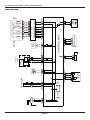
W
IRING DIAGRAM
7 6 5 4 3 2 1 1 2
4
2
1 3 5 7
6 8 9
1 2 3 54 6 8
7 9 10
321
3
2 1
212
1
12
2 1
2 1
1 2
2 1
21
1 2
2 1
1 2
2 1 1234
2 3 41
2 1
1
2
on/off
1 2 43
3 12
6
7 5 4 3 2 1 1 2
Double
Valve
GRN
RFI
L
BK
BK
IF2
SMPS
DOOR LOCK
BK
BK
BK
DLS3 DP2
PUMP
R
R
BU
BU
BU
VPW3
COLD FILL
VALVE
BLEACH
VALVE
VW3 VHF3
HOT
VALVE
BU
BU
MOTOR
Vcc
GND
12V
PRS2 PR2
BU
BU
BR
BR
PRESSURE
SWITCH
NTC
SET2
OR
OR
GRN
UI4
BU
BU
BU
BU
USER MODULE
Vcc
Vcc
DOOR
SWITCH
DU3
BU
BU
CONTROL UNIT
M7
OR
OR
OR
OR
OR
OR
OR
BU
BK
L
N
SPRCTCPCT1T2
–12V
MCU
BR
BR
BR
BR
BR
BR
BR
BR
BR
MS2
GRN
STATOR
TACHO
PROTECTOR
ROTOR
STATOR

FOR SERVICE TECHNICIAN ONLY - DO NOT REMOVE OR DESTROY
PAGE 18
N
OTES

PAGE 19
G
UIDE DE DIAGNOSTIC
Avant d’entreprendre une réparation, contrôler ce qui suit :
• Vérifier que la prise de courant est alimentée.
• Fusible grillé ou disjoncteur ouvert? Fusible temporisé grillé?
• Robinets d’eau chaude et d’eau froide ouverts et tuyaux d’arrivée
d
’eau exempts d’obstruction?
• Utiliser pour tous les contrôles un voltmètre ou autre instrument
dont la résistance interne est de 20 000 ohms par volt CC ou plus.
• Contrôler toutes les connexions avant de remplacer un
composant. Rechercher des fils brisés ou mal connectés,
o
u des bornes ou cosses de connexion détériorées.
• Le non-fonctionnement d’un organe de commande peut être dû
à la corrosion des pièces de connexion. Inspecter les connexions
et contrôler la continuité avec un ohmmètre.
• Connecteurs : Examiner le sommet d’un connecteur; rechercher
des fils brisés ou mal connectés; rechercher également des
cosses mal branchées.
• Lors de toute mesure de résistance, vérifier que le cordon
d’alimentation est débranché de la prise de courant, et que
le faisceau de câblage ou le connecteur est débranché.
CAUSES POSSIBLES/TEST
NOTE : Pour chaque problème, on doit exécuter les opérations “Causes possibles/Test”
PROBLÈME dans l’ordre indiqué.
PAS DE MISE EN MARCHE 1. Vérifier que la laveuse est branchée à une prise de courant fonctionnelle et qu’aucun fusible
(aucune réaction lors des n’est grillé.
pressions sur les boutons) 2. Vérifier que la tension alimente le module de commande central (MCC) : un clic à l’intérieur
du module de commande central est audible lorsque la laveuse est branchée. En l’absence
de clic, remplacer le MCC.
3. Débrancher la laveuse ou déconnecter la source de courant électrique.
4. Vérifier la continuité du cordon d’alimentation électrique et du filtre de ligne.
5. Vérifier les connexions du faisceau de câblage au MCC.
6. Brancher la laveuse ou reconnecter la source de courant électrique.
7. Contrôler le fonctionnement de l’ensemble des boutons/DEL : sélectionner divers programmes
et changer les réglages et options disponibles pour vérifier que l’ensemble des boutons/DEL réagit.
8. Vérifier la connexion du cordon d’alimentation électrique au filtre de ligne et au MCC. Vérifier
que la porte se ferme entièrement.
MISE EN MARCHE D’UN 1. Ouvrir et fermer la porte. La porte doit être ouverte entre deux programmes de lavage consécutifs.
PROGRAMME IMPOSSIBLE 2. Contrôler le module de contacteur de porte/verrouillage : exécuter le test de diagnostic.
Voir le test de diagnostic rapide.
3. Si la porte est verrouillée, effectuer une vidange.
4. Débrancher la laveuse ou déconnecter la source de courant électrique.
5. Vérifier les connexions du faisceau de câblage.
6. Brancher la laveuse ou reconnecter la source de courant électrique.
7. Contrôler le fonctionnement de l’ensemble des boutons/DEL : sélectionner divers programmes
et changer les réglages et options disponibles pour vérifier que l’ensemble des boutons/DEL réagit.
GUIDE DE DÉPANNAGE
NOTE : Une fois le ou les problèmes résolus, effectuer le test de diagnostic pour vérifier qu’il n’existe aucun autre problème.
POUR LE TECHNICIEN SEULEMENT - NE PAS ENLEVER NI DÉTRUIRE
IMPORTANT
Circuits électroniques sensibles
aux décharges électrostatiques
Le risque de décharge électrostatique est permanent. Une
décharge électrostatique peut endommager ou affaiblir les
composants électroniques. La nouvelle carte peut donner
l’impression qu’elle fonctionne correctement après la réparation,
mais une décharge électrostatique peut lui avoir fait subir des
dommages qui provoqueront une défaillance plus tard.
■
Utiliser un bracelet de décharge électrostatique. Connecter
le bracelet à la vis verte de liaison à la terre ou sur une
surface métallique non peinte de l’appareil.
-OU-
Toucher plusieurs fois du doigt la vis verte de liaison à la terre
ou une surface métallique non peinte de l’appareil.
■
Avant de retirer la pièce de son sachet, placer le sachet
antistatique en contact avec la vis verte de liaison à la terre
ou une surface métallique non peinte de l’appareil.
■
Éviter de toucher les composants électroniques ou les
broches de contact; tenir la carte de circuits électroniques
par les bords seulement lors des manipulations.
■
Lors du réemballage d’une carte de circuits électroniques
défaillante dans le sachet antistatique, appliquer les
instructions ci-dessus.

PAGE 20
POUR LE TECHNICIEN SEULEMENT - NE PAS ENLEVER NI DÉTRUIRE
CAUSES POSSIBLES/TEST
NOTE : Pour chaque problème, on doit exécuter les opérations “Causes possibles/Test”
PROBLÈME dans l’ordre indiqué.
ARRÊT IMPOSSIBLE 1. Vérifier un code de défaillance/erreur sur l’affichage.
2. Tourner le bouton de commande de programmes à la position OFF (arrêt).
3. Contrôler le fonctionnement de l’ensemble des boutons/DEL : sélectionner divers programmes
et changer les réglages et options disponibles pour vérifier que l’ensemble des boutons/DEL réagit.
4. Débrancher la laveuse ou déconnecter la source de courant électrique.
5. Vérifier l’absence d’obstruction dans le tuyau de vidange et sur le filtre de la pompe de vidange
(matières étrangères, etc.).
6. Brancher la laveuse ou reconnecter la source de courant électrique.
7. Inspecter la pompe de vidange.
8. Vérifier le bon fonctionnement du MCC : exécuter un test de diagnostic rapide ou d’un autre
programme.
9. Vérifier le bouton sur le MCC pour contrôler que le sens est correct. Voir page 30.
LE SYSTÈME DE 1. Tourner le bouton de commande de programmes à la position OFF (arrêt).
COMMANDE N’ACCEPTE 2. Effectuer une vidange et vérifier l’absence d’obstruction dans le tuyau de vidange et sur le filtre
PAS LES SÉLECTIONS de la pompe de vidange (matières étrangères, etc.)
3. Contrôler le fonctionnement de l’ensemble des boutons/DEL : exécuter le mode de test universel.
4. Débrancher la laveuse ou déconnecter la source de courant électrique.
5. Vérifier les connexions du faisceau de câblage.
6. Brancher la laveuse ou reconnecter la source de courant électrique.
7. Vérifier le bon fonctionnement du MCC : exécuter un test de diagnostic ou d’un autre programme.
DISTRIBUTION DE PRODUIT 1. Vérifier que la laveuse est d’aplomb.
IMPOSSIBLE 2. Vérifier que le tiroir distributeur n’est pas obstrué par du détergent.
3. Inspecter les raccordements d’eau vers la laveuse et à l’intérieur de la laveuse. Vérifier que
la crépine de l’arrivée d’eau n’est pas colmatée.
4. Vérifier l’arrivée d’eau et l’électrovanne.
5. Débrancher la laveuse ou déconnecter la source de courant électrique.
6. Vérifier les connexions du faisceau de câblage.
7. Brancher la laveuse ou reconnecter la source de courant électrique.
8. Vérifier le bon fonctionnement du MCC : exécuter un test de diagnostic rapide ou d’un autre
programme.
REMPLISSAGE IMPOSSIBLE 1. Vérifier l’installation. Vérifier que les robinets d’eau chaude et d’eau froide sont ouverts.
2. Inspecter les électrovannes d’arrivée.
3. Débrancher la laveuse ou déconnecter la source de courant électrique.
4. Contrôler les raccordements d’eau vers la laveuse et à l’intérieur de la laveuse. S’assurer
que les tuyaux d’alimentation en eau ne sont pas obstrués. Vérifier que la crépine de l’arrivée
d’eau n’est pas colmatée.
5. Brancher la laveuse ou reconnecter la source de courant électrique.
6. Vérifier le bon fonctionnement du manocontacteur.
7. Inspecter le moteur de la pompe de vidange.
8. Vérifier le bon fonctionnement du MCC : exécuter un test de diagnostic rapide ou d’un autre
programme.
9. Consulter les étapes énumérées sous la section DISTRIBUTION DE PRODUIT IMPOSSIBLE.
OVERFILLS 1. Vérifier que la laveuse est d’aplomb.
2. Inspecter le système de vidange de la pompe – Ce symptôme peut indiquer une défaillance
de la vidange.
3. Débrancher la laveuse ou déconnecter la source de courant électrique.
4. Vérifier le bon fonctionnement du manocontacteur.
5. Inspecter le tuyau du manocontacteur.
6. Brancher la laveuse ou reconnecter la source de courant électrique.
7. Vérifier le fonctionnement du débitmètre en injectant de l’air dans la pièce et en mesurant sa résistance.
8. Vérifier le bon fonctionnement du MCC : exécuter un test de diagnostic rapide ou d’un autre
programme.
AUCUNE ROTATION 1. Inspecter la courroie de transmission.
DU PANIER 2. Inspecter le moteur d’entraînement.
3. Débrancher la laveuse ou déconnecter la source de courant électrique.
4. Vérifier les connexions du faisceau de câblage.
5. Brancher la laveuse ou reconnecter la source de courant électrique.
6. Effectuer le test de continuité du moteur.
ÉCHAUFFEMENT EXCESSIF 1. Inspecter le moteur d’entraînement.
DU MOTEUR 2. Débrancher la laveuse ou déconnecter la source de courant électrique.
3. Vérifier les connexions du faisceau de câblage.
4. Inspecter la courroie de transmission.
5. Brancher la laveuse ou reconnecter la source de courant électrique.
6. Vérifier l’absence d’obstruction entre le panier d’essorage et la cuve externe.
G
UIDE DE DÉPANNAGE
NOTE : Une fois le ou les problèmes résolus, effectuer le test de diagnostic pour vérifier qu’il n’existe aucun autre problème.
La page charge ...
La page charge ...
La page charge ...
La page charge ...
La page charge ...
La page charge ...
La page charge ...
La page charge ...
La page charge ...
La page charge ...
La page charge ...
La page charge ...
La page charge ...
La page charge ...
La page charge ...
La page charge ...
-
 1
1
-
 2
2
-
 3
3
-
 4
4
-
 5
5
-
 6
6
-
 7
7
-
 8
8
-
 9
9
-
 10
10
-
 11
11
-
 12
12
-
 13
13
-
 14
14
-
 15
15
-
 16
16
-
 17
17
-
 18
18
-
 19
19
-
 20
20
-
 21
21
-
 22
22
-
 23
23
-
 24
24
-
 25
25
-
 26
26
-
 27
27
-
 28
28
-
 29
29
-
 30
30
-
 31
31
-
 32
32
-
 33
33
-
 34
34
-
 35
35
-
 36
36


Maytag MHWC7500YW0 Manuel utilisateur
- Catégorie
- Machines à laver
- Taper
- Manuel utilisateur
dans d''autres langues
- English: Maytag MHWC7500YW0 User manual
Documents connexes
Autres documents
-
Whirlpool WFW9400SZA10 Troubleshooting guide
-
-
-
-
-
-
-
-
-
Whirlpool Washer Manuel utilisateur