Kathrein BAS 60 Mode d'emploi
- Catégorie
- Antennes satellites
- Taper
- Mode d'emploi

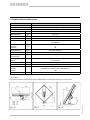
BAS 60, 216195
Flachantenne für mobile Anwendung
ein Ausgang schaltbar
935.2018/H/0806/1.12d
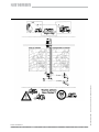
1. Bestimmungsgemäßer Gebrauch
Die Flachantenne BAS 60 dient zum Empfang von analogen und digitalen TV-, Radio und anderen
Satellitensignalen im Frequenzbereich von 10,70 bis 12,75 GHz.
Terrestrische Signale können nicht empfangen werden.
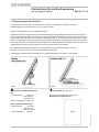
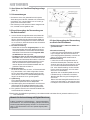
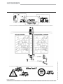
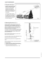
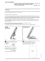
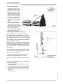
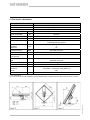
Die BAS 60 ist für den mobilen Einsatz zum Satellitenempfang auf dem stillstehenden Caravan, Wohnmobil, Lkw
oder nicht gewerblich genutzten Binnenschiff konzipiert. Die Befestigungskonstruktion der Antenne ist auf die Sat-
Gelenkmaste HDM 140, HDM 141 und HDM 143 abgestimmt (Abb. 1), wobei die Ausrichtung der Antenne mittels
Kurbel- bzw. Mastdrehung aus dem Fahrzeuginneren heraus erfolgt. Wenn eine Montage auf dem Caravan/Wohn-
mobil nicht gewünscht ist, empfi elt sich eine Montage mit dem Stativ-Sat-Gelenkmast HDS 150. Mit ihm haben Sie
die Möglichkeit die Antenne in der Nähe Ihres Fahrzeugs auf der Erde zu aufzustellen.
Eine weitere Montagemöglichkeit besteht in der Kombination mit der Dreheinheit HDP 171 (Abb. 2).
Bei dieser Anwendung wird die Antenne vollautomatisch ausgerichtet.
Die Montage der BAS 60 auf der Dreheinheit ist in der Montageanleitung des HDP 171 beschrieben.
Vorgeschriebenes Befestigungszube-
hör:
• Sat-Gelenkmast HDM 140
oder HDM 141
oder HDM 143
Stativ-Sat-Gelenkmast HDS 150
Weitere Zubehörempfehlungen:
• Digital-Receiver UFS 601si
oder UFD 170
oder UFS 740sw
• Verbindungskabel HDK 80
Dreheinheit HDP 171, 20410018
Alle weiteren notwendigen Angaben siehe
Montageanleitung bei HDP 171.

935.2018/H/0806/2.12d
2. Hinweise zur StVZO
• Bei Festinstallation der Satellitenanlage auf einem Kfz, das am öffentlichen Straßenverkehr teilnimmt, sind die
geltenden Vorschriften nach StVZO zu beachten.
Ein Eintrag in den Fahrzeugpapieren nach § 19/2 StVZO ist nicht erforderlich, sofern die Antenneneinheit in einer
Mindesthöhe von 2 m angebracht wird, sie nicht über die äußeren Fahrzeugumrisse hinausragt und bei herunter-
geklappter Antenne (Parkposition) eine Fahrzeuggesamthöhe von 4 m nicht überschritten wird.
3. Wichtige Hinweise zum Gebrauch
• Die nachfolgend aufgeführten Sachverhalte führen zum Ver-
lust von Garantie- und Haftungsansprüchen gegenüber dem
Hersteller:
- Unsachgemäße Montage
- Verwendung von hier nicht genannten Befestigungszubehör,
wodurch die mechanische Sicherheit der Antennenanlage in
diesem Fall nicht gewährleistet werden kann
- Unzulässiger Gebrauch wie z.B. die Nutzung der Flachan
tenne als Ablage
- Bauliche Veränderungen oder Eingriffe an der Antenne oder
dem Befestigungszubehör, wodurch sowohl die mechani
sche als auch die funktionelle Sicherheit gefährdet sind
- Gewaltsames Öffnen der Antenne (möglicher Funktionsaus
fall)
- Verwendung von lösemittelhaltigen Reinigern wie Azeton,
Nitro-/Farbverdünner, Benzin o.ä.
- Missachtung der weiteren Hinweise dieser Anleitung
Achtung!
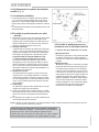
• Vor Antritt der Fahrt ist die Antenne stets in die horizontale Position (Parkposition) zu stellen. Dazu muss der
Gelenkmast bis auf Anschlag abgesenkt werden (der Gelenkkopf liegt dann auf der Dichtungsmanschette auf).
Bringen Sie als Erinnerung hierzu den auf Seite 1 angebrachten Aufkleber im Sichtbereich des Zündschlosses
an.
• Nach Kollision der Antenne mit Ästen o.ä. Gegenständen ist die Antennenanlage auf Festsitz zu überprüfen.
'DGLH$QWHQQHLP)DKUEHWULHE6FKZLQJXQJVEHODVWXQJHQDXVJHVHW]WLVWPXVVMHQDFK)DKUKlX¿JNHLWGHU)HVW
sitz der Antennenanlage in regelmäßigen Abständen kontrolliert und gelockerte Teile festgezogen werden.
• Die maximal zulässige Höchstgeschwindigkeit mit angebrachter Flachantenne beträgt 130 km/h.
Senken Sie die Antenne bei längerem Nichtgebrauch ab. Die Feststellschrauben sind dann schwerer zugänglich
'LHEVWDKOVFKXW]$XIGHQIROJHQGHQ6HLWHQ¿QGHQ6LHZHLWHUHZLFKWLJH+LQZHLVH]XPVLFKHUHQ*HEUDXFKGHU
Antenne, die Sie unbedingt beachten sollten.
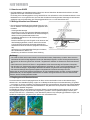
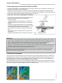
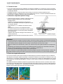
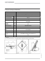
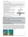
4. Empfangsbereich/Ausleuchtzone
Die Ausleuchtzone ist das Empfangsgebiet auf der Erde, welches der Satellit mit seinem Sendestrahl (Spot)
abdeckt und in dem Satellitenempfang möglich ist. Im Mittelpunkt dieses Spots ist die Senderleistung am größten
– nach außen hin wird sie schwächer. Ihre Antenne werden Sie vorzugsweise auf die Position der ASTRA Satelliten
19,2° Ost (Bild unten links) oder EUTELSAT/HOTBIRD 13° Ost (Bild unten rechts) ausrichten. Nachstehend sind
die Spots dieser Satelliten dargestellt.
Die Satelliten strahlen die verschiedenen Programm-Pakete in unterschiedlichen Ausleuchtzonen ab. Im Haupt-
empfangsgebiet (innere Linie) können alle Programme in guter Bild- und Tonqualität empfangen werden (Aus-
nahme: EUTELSAT II F1 – Wide Beam). In den Randzonen (äußere Linie) ist Empfang grundsätzlich möglich, die
Qualität der empfangenen Programme kann jedoch sehr unterschiedlich sein.

935.2018/H/0806/3.12d
5. Empfangsort
• Für den Satellitenempfang ist
es unbedingt notwendig, dass
sich am Empfangsort zwischen
Antenne und Satellit keine
+LQGHUQLVVHEH¿QGHQ$FKWHQ
Sie deshalb darauf, dass die
Antenne nicht durch Dachauf-
bauten wie z.B. Dachkoffer,
Klimaanlagen, Solarpaneele,
Bäume, Gebäude etc. abge-
schattet wird.
Beachten Sie, dass die Anlage
eine gedachte freie Sicht nach
Süden in einem Winkel von 15°
bis 55° gegenüber der Horizon-
talen benötigt und dass diese
Linie nicht unterbrochen wird.
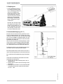
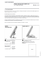
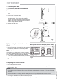
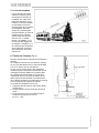
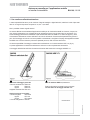
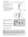
6. Antennenbefestigung (Abb. 6)
Montieren Sie den Antennenmast gemäß den Anwei-
sungen des Mastherstellers. Am Caravan oder Wohn-
mobil kann die Antenne mit dem Sat-Gelenkmast HDM
140, am Lkw mit HDM 141 befestigt werden. Für eine
Montage auf der Erde verwenden Sie bitte den Stativ-
Sat-Gelenkmast HDS 150.
Wenn Sie Ihre terrestrische Empfangsanlage, die Sie
mit der HD 35 und dem Shapeg-Inanten-Mast HDM
135 aufgebaut haben, auf Satellitenempfang umstel-
len, verwenden Sie bitte den Gelenkmast HDM 143.
Die Dachdurchführung und die Befestigungskonsole
vom HDM 135 kann weiterverwendet werden.
Mit diesen Masten lässt sich die Antenne aus dem In-
neren des Fahrzeugs bequem und schnell ausrichten.
Eine ausführliche Montageanleitung liegt den Masten
bei.
Gehen Sie bei der Montage der Masten bzw. Stativ-
Sat-Gelenkmast wie folgt vor:
1. Bereiten Sie den Mast-Gelenkkopf wie in Abb. 6
dargestellt wird
2. Stecken Sie die Antenne bis auf Anschlag auf den
Gelenkkopf
3. Befestigen Sie die Antenne mit der Schließschelle
Anzugsdrehmoment der beiden M-6-Schrauben:
M = 6,5 + 1 Nm

935.2018/H/0806/4.12d
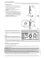
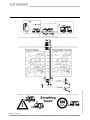
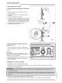
7. Kabelanschluss
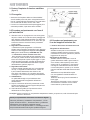
7.1 Kabelanschluss an der Antenne (Abb. 7)
1. Entfernen Sie die LNB-Schutzhaube nach Locke-
rung der zwei Rändelschrauben
2. Montieren Sie den beiliegenden F-Stecker wie
abgebildet
3. Schrauben Sie das Kabel am LNB an
4. Drücken Sie das angeschlossene Kabel (Mantel-
durchmesser: 6,8) in den Kabelhalter. Falls Sie ein
dünneres Kabel (z.B. bei Sat-Gelenkmasten HDM
xxx in verkabelter Ausführung) verwenden, drücken
Sie zuvor zum Durchmesserausgleich die beilie-
gende Hülse auf das Kabel.
5. Montieren Sie die LNB-Schutzhaube.
7.2 Kabelanschluss am Receiver (Abb. 8)
• Montieren Sie am receiverseitigen Kabelende einen
F-Stecker. Kabel und Steckervorbereitung gemäß
Abb. 7.
Hinweis:
Bei älteren Receivern ist es möglich, dass hierzu ein
IEC-Winkelstecker verwendet werden muss, der im
Lieferumfang des Verbindungskabels HDK 80 enthal-
ten ist.
• Stellen Sie die Verbindung zwischen der BAS 60
und dem Receiver her. Schließen Sie hierzu das Ka-
bel an der Rückseite des Receivers am Sat-Eingang
„IF-IN“ an.
8. Einstellen des Satelliten-Receivers
• Bei TV-Geräten mit Scart-Anschluss:
Verbinden Sie das TV-Gerät über Audio-/Video-Kabel mit dem Satelliten-Receiver und wählen Sie am TV-Gerät
den Programmplatz „AV“.
Hinweis:
• Die Digital-Receiver UFS 601si, UFD 170 und UFS 740sw sind für den Betrieb an TV-Geräten mit Scart-An-
schluss ausgelegt
• Stellen Sie in der Grundeinstellung des Receivers den Menüpunkt „22-kHz-Signal“ auf „High/Low“ ein
• Nähere Information zur Änderung der Grundeinstellungen entnehmen Sie der Bedienungsanleitung der Receiver
• Wählen Sie zur Einstellung am Satelliten-Receiver das gewünschte Programm.
Der Satelliten-Receiver ist werksseitig vorprogrammiert (siehe Programm-Tabelle des Satelliten-Receivers)
Rückseite Receiver-Beispiel (Teilansicht)
Abb. 8

935.2018/H/0806/5.12d
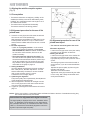
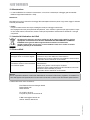
9. Ausrichten der Satelliten-Empfangsanlage
(Abb. 9)
9.1 Voraussetzungen
• Die Antenne muss eine gedachte freie Sicht (keine
Abschattung durch Bäume, Gebäude o.ä. Hindernisse)
nach Süden, d.h. in einem Winkel von 15° bis 55° ge-
genüber der Horizontalen haben.
• Das Fahrzeug und die Antenne müssen waagrecht ste-
hen, der Mast muss eingefahren sein.
9.2 Ausrichtvorgänge bei Verwendung von
Sat-Gelenkmasten
1. Lockern Sie die Kreuzgriffschraube an der Mast-Hal-
tekonsole sowie die Konusmutter an der Dachdurch-
führung. Schieben Sie den Antennenmast (HDM 140,
HDM 143) aus der abgesenkten Position mindestens
13 cm nach oben, damit die Antenne beim Schwenken
nicht auf das Dach stößt.
2. Elevationseinstellung
• Stellen Sie am Receiver Programmplatz 1 ein. Die-
ser Programmplatz ist bei allen Kathrein-Receivern
und bei den meisten in Deutschland auf dem Markt
befi ndlichen Fremdreceivern dem Programm ARD
auf ASTRA 19,2° Ost zugeordnet.
• Die Antenne muss in etwa nach Süden ausgerich
tet werden. Dann drehen Sie rechtsorientiert mit der
Handkurbel am Gelenkmast die Antenne in die Ihrem
Standort entsprechende Elevationsposition. Die An-
zahl der erforderlichen Kurbelumdrehungen ent-
nehmen Sie der Azimut-/Elevationstabelle oder der
grafi schen Übersicht auf Seite 12.
3. Azimuteinstellung
Die Antenne haben Sie, wie unter „2. Elevationseinstel-
lung“ beschrieben, nach süden ausgerichtet. Drehen
Sie nun den Antennenmast langsam nach links oder
rechts, bis Sie auf dem TV-Gerät die Bildsignale emp-
fangen. Die Antenne ist nun grob eingestellt.
4. Optimierung
Durch feinfühliges Nachstellen von Elevations- und
Azimutwinkel optimieren Sie Ihre Bildqualität.
5. Nach Beendigung der Ausrichtarbeiten sind die Kreuz-
griffschraube an der Mastgriff-Haltekonsole und die
Konusmutter an der Dachdurchführung festzuziehen.
6. Eine grafi sche Übersicht zum schnellen Einstellen der
Antenne fi nden Sie auf Seite 12.
Tipp: Stecken Sie die Bedienungsanleitung in eine Klarsichthülle und kleben Sie sie, jederzeit erreichbar, z.B. in
eine Schranktüre.
9.3 Ausrichtvorgänge bei Verwendung
von Stativ-Sat-Gelenkmast
• Die Antenne muss in etwa nach Süden aus-
gerichtet werden.
1.Elevationseinstellung
Lockern Sie die Kreuzgriffschraube am Gelenk-
kopf und kippen Sie die Antenne zunächst in
einen Neigungswinkel (Elevation) von etwa 30°.
Ziehen Sie die Schraube wieder leicht an.
2.Azimuteinstellung
Lockern Sie nun die Kreuzgriffschraube am
Schaft des Gelenkkopfes und drehen Sie die
Antenne nach links und rechts (Azimut), bis Sie
am TV-Gerät erste Bildeindrücke bekommen.
Evtl. muss diese Einstellung mit einer zweiten
Person durch Zuruf erfolgen, wenn Sie keine
Sicht zum TV-Gerät haben.
Optimieren Sie nun die Bildqualität durch eine
Feinabstimmung von Elevation und Azimut.
Beachten Sie dazu den grau hinterlegten Hin-
weis unten.
Ziehen Sie beide Kreuzgriffschrauben fest und
verlegen Sie das Kabel so, dass niemand darü-
ber stolpern und sich dadurch verletzen könnte.
Hinweis für die Ausrichtung mit Digital-Receivern
Im Menü „Installation und Einstellungen“, „Antenneneinstellung
und Kanalsuche“ und „Antennenempfang“ (Beispiel UFS 601si)
wird die Signalqualität angezeigt. Mit UFD 170 und Dreheinheit
HDP 171 wird automatisch immer auf optimale Signalqualität
ausgerichtet.

935.2018/H/0806/6.12d
10. Wartung
• Die BAS 60 ist, wie das Befestigungszubehör (HDM-Gelenkmaste und Stativ-Gelenkmast), wartungsfrei.
Achtung!
Dennoch ist die Antennenanlage vor Fahrtantritt auf Festsitz zu überprüfen und gegenenfalls gelockerte Teile sind
festzuziehen.
• Reinigung
Reinigen Sie die Antenne nur mit Wasser oder den im Kfz-Bereich üblichen Wasch- und Reinigungsmitteln.
Verwenden Sie keinesfalls Dampfstrahl- oder Hochdruck-Reiniger.
Verwenden Sie keinesfalls lösemittelhaltige Reiniger wie Azeton, Nitro-Farbverdünnung, Benzin o.ä., durch die
die Antenne zu Schaden kommen könnte.
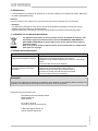
11. Entsorgungshinweis
Elektronische Geräte gehören nicht in den Hausmüll, sondern müssen - gemäß Richtlinie
2002/96/EG DES EUROPÄISCHEN PARLAMENTS UND DES RATES vom 27. Januar 2003
über Elektro- und Elektronik-Altgeräte fachgerecht entsorgt werden.
Bitte geben Sie dieses Gerät am Ende seiner Verwendung zur Entsorgung an den dafür
vorgesehenen öffentlichen Sammelstellen ab.
12. Funtionsstörungen
Störung Mögliche Ursachen
- Kein Bild
- Standbild bei Digitalempfang
- Hindernis zwischen Antenne und Satellit
$QWHQQHEH¿QGHWVLFKDXHUKDOEGHU$XVOHXFKW]RQH
- TV-Gerät oder Receiver sind defekt oder erhalten keine Spannung
- Stecker des Antennenkabels ist locker
- Schlechte Bildqualität
- Blockbildung bei Digitalempfang
- Hindernis zwischen Antenne und Satellit - teilweise Abschattung des
Antennensignals
- Laub, Schnee, Eis o.ä. bedeckt die Antenne
$QWHQQHEH¿QGHWVLFKDP5DQGHGHU$XVOHXFKW]RQHHYHQWXHOOLVWHLQ
stärkerer
Sender noch empfangbar
- Stecker des Antennenkabels ist locker
Hinweis!
Sollten Sie eine auftretende Störungsursache nicht erkennen oder beheben können, setzen Sie sich bitte mit
Ihrem Fachhändler bzw. mit unserer Servicestelle in Verbindung. Öffnen Sie keinesfalls die Antenne.
Die Anschrift unserer Servicestelle lautet:
ESC Elektronik Service Chiemgau GmbH
Bahnhofstraße 108
83224 Grassau
Tel. (0 86 41) 95 45-0
Fax (0 86 41) 95 45 35 und 95 45 36
Internet: www.esc-kathrein.de

935.2018/H/0806/7.12d
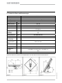
13. Technische Daten und Abmessungen
Typ BAS 60
Bestell-Nr. 216195
Einsatzgebiet Mobile Anwendung
Befestigungsmöglichkeit an HDP 171, HDM 140, 141, 143, HDS 150
Empfangsbereich GHz 10,70-12,75
LNB-Rauschmaß dB Typ. 0,8
Verstärkung dB > 50
Halbwertsbreite ° < 3
1)
LNB 1 Ausgang schaltbar
H/V, high/low
Umschaltung
Low-Band
High-Band
kHz 0
22
Ausgangsfrequenz MHz 950-1950/1100-2150
Oszillatorfrequenz GHz 9,75/10,6
Güte (G/T)
11,3/12,5 GHz
dB/K 13,3/13,7
LNB-
Versorgungsspan-
nung
V Vert.: 11,5-14,0
Horiz.: 16,0-19,0
Max. Stromaufnah-
me
mA 160
Windlast N 240
2)
Einstellbereich
Elevation
Azimut
0-90 (HDM xxx und HDS 150), 10-90 (HDP 171)
360
Gewicht kg 5,4
1) Bei Bandmitte
2) Bei einem Staudruck von 800 N/m
2
nach DIN EN 50083-1 bzw. VDE 0855 und Antenne senkrecht stehend.

935.2018/H/0806/8.12d
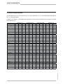
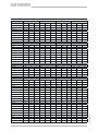
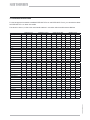
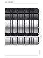
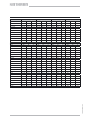
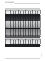
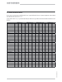
14. Azimut-/Elevationstabelle
Als erste Näherung können für EUTELSAT II F2 10° und für EUTELSAT II F3 16° die Tabellenwerte des EUTELSAT
II F1 13° verwendet werden.
Die Werte in der Spalte „U“ (U=Kurbelumdrehung) beziehen sich auf Kurbelumdrehungen bei Verwendung von BAS
60 als Mobilantenne.
ASTRA 19,2° Ost EUTELSAT 13,0° Ost Atlantic Bird 5,0° West ASTRA 28,2° Ost
Deutschland Az El U Az El U Az El U Az El U
Bad Reichenhall 171,5 34,9 4 3/4 179,9 35,2 4 3/4 203,6 32,5 5 1/4 159,7 33,20 5
Berlin 172,7 29,7 5 1/4 180,5 30,0 5 1/4 202,8 27,6 5 1/4 161,6 28,4 5 1/4
Bremen 167,1 28,6 5 1/4 174,8 29,2 5 1/4 197,1 28,0 5 1/4 156,3 26,8 5 1/2
Cottbus 173,8 30,6 5 181,7 30,8 5 204,1 28,1 5 1/4 162,5 29,4 5 1/4
Dortmund 165,1 30,0 5 1/4 172,9 30,8 5 195,8 29,9 5 1/4 154,2 27,9 5 1/4
Dresden 173,0 31,3 5 180,9 31,6 5 203,6 28,9 5 1/4 161,6 30 5 1/4
Emden 165,2 28,1 5 1/4 172,8 28,8 5 1/4 195,1 28,0 5 1/4 154,9 26,2 5 1/2
Erfurt 169,5 31,1 5 1/2 175,7 27,4 5 1/2 197,5 26,2 5 1/2 158,3 29,4 5 1/4
Flensburg 168,1 26,9 5 1/2 175,7 27,4 5 1/2 197,5 26,2 5 1/2 157,4 25,3 5 1/2
Frankfurt/Main 166,4 31,7 5 174,4 32,4 5 197,6 31,1 5 155,2 29,6 5 1/4
Freiburg 164,9 33,8 4 3/4 173,1 34,7 4 3/4 197,0 33,5 4 3/4 153,5 31,4 5
Greifswald 172,8 28,0 5 1/4 180,5 28,3 5 1/4 202,3 26,0 5 1/2 161,9 26,8 5 1/2
Hamburg 168,6 28,3 5 1/4 176,3 28,8 5 1/4 198,4 27,3 5 1/2 157,7 26,6 5 1/2
Hannover 168,2 29,5 5 1/4 175,9 30,1 5 1/4 198,4 28,6 5 1/4 157,2 27,7 5 1/4
Kassel 167,6 30,6 5 175,4 31,2 5 198,3 29,7 5 1/4 156,5 28,7 5 1/4
Kiel 168,89 27,47 5 1/2 176,47 27,97 5 1/4 198,42 26,50 5 1/2 158,1 25,9 5 1/2
Koblenz 164,94 31,27 5 172,87 32,10 5 196,07 31,12 5 153,9 29,1 5 1/4
Leipzig 171,27 30,93 5 179,19 31,28 5 201,84 29,05 5 1/4 160 29,4 5 1/4
Magdeburg 170,45 29,98 5 1/4 178,27 30,39 5 1/4 200,73 28,41 5 1/4 159,3 28,4 5 1/4
M‘gladbach 163,81 30,19 5 1/4 171,62 31,09 5 194,57 30,42 5 1/4 152,9 27,9 5 1/4
München 169,80 34,24 4 3/4 178,08 34,72 4 3/4 201,77 32,45 5 158,1 32,4 5
Neubrandenburg 172,62 28,60 5 1/4 180,31 28,85 5 1/4 202,29 26,59 5 1/2 161,6 27,3 5 1/2
Nürnberg 169,33 32,76 5 177,43 33,27 5 200,74 31,25 5 157,9 31 5
Osnabrück 166,01 29,32 5 1/4 173,75 30,04 5 1/4 196,33 28,99 5 1/4 155,1 27,3 5 1/2
Passau 172,37 33,99 4 3/4 180,62 34,26 4 3/4 204,01 31,48 5 160,7 32,5 5
Pirmasens 164,83 32,48 5 172,88 33,33 5 196,45 32,29 5 153,6 30,2 5 1/4
Plauen 170,87 31,77 5 178,88 32,15 5 201,78 29,91 5 1/4 159,5 30,2 5 1/4
Ravensburg 167,13 34,45 4 3/4 175,41 35,04 4 3/4 199,38 33,33 5 155,6 32,2 5
Regensburg 170,63 33,36 5 178,81 33,77 4 3/4 202,17 31,41 5 159,1 31,7 5
Rostock 171,30 27,94 5 1/4 178,93 28,27 5 1/4 200,84 26,32 5 1/2 160,4 26,6 5 1/2
Stuttgart 166,79 33,18 5 174,93 33,89 4 3/4 198,57 32,36 5 155,4 31,1 5
Trier 163,72 31,72 5 171,68 32,65 5 195,10 31,90 5 152,6 29,4 5 1/4
Ulm 167,13 33,75 4 3/4 175,95 34,39 4 3/4 199,68 32,60 5 156,2 31,7 5

935.2018/H/0806/9.12d
ASTRA 19,2° Ost EUTELSAT 13,0° Ost Atlantic Bird 5,0° West ASTRA 28,2° Ost
Österreich Az El U Az El U Az El U Az El U
Bregenz 167,28 34,66 4 3/4 175,60 35,34 4 3/4 199,65 33,56 4 3/4 155,7 32,5 5
Graz 174,88 35,78 4 3/4 183,34 35,85 4 3/4 206,99 32,33 5 162,8 34,5 4 3/4
Innsbruck 169,41 35,78 4 3/4 177,80 35,67 4 3/4 201,81 33,38 5 157,6 33,3 5
Klagenfurt 173,32 36,17 4 3/4 181,83 36,37 4 3/4 205,76 33,12 5 161,2 34,7 4 3/4
Lienz 171,21 35,79 4 3/4 179,68 36,16 4 3/4 204,72 33,41 4 3/4 159,3 34,1 4 3/4
Linz 173,45 34,35 4 3/4 181,74 34,45 4 3/4 205,13 31,49 5 161,7 32,9 5
Salzburg 171,70 34,78 4 3/4 180,04 35,10 4 3/4 203,72 32,37 5 159,9 33,2 5
Wien 176,20 34,60 4 3/4 184,51 34,57 4 3/4 207,69 30,93 5 164,3 33,5 4 3/4
ASTRA 19,2° Ost EUTELSAT 13,0° Ost Atlantic Bird 5,0° West ASTRA 28,2° Ost
Benelux-Länder Az El U Az El U Az El U Az El U
Brugge 159,82 29,47 5 1/4 167,53 30,65 5 190,49 30,86 5 149,1 26,9 5 1/2
Bruxelles 161,12 30,10 5 1/4 168,90 31,20 5 191,99 31,10 5 150,3 27,6 5 1/4
Den Haag 161,35 28,79 5 1/4 169,01 29,84 5 1/4 191,70 29,77 5 1/4 150,7 26,4 5 1/2
Eindhoven 162,64 29,74 5 1/4 170,40 30,71 5 193,29 30,32 5 1/4 151,8 27,4 5 1/2
Enschede 164,56 29,19 5 1/4 172,28 30,02 5 1/4 194,91 29,37 5 1/4 153,7 27,1 5 1/2
Groningen 164,39 28,07 5 1/4 172,01 28,88 5 1/4 194,35 28,24 5 1/4 153,7 26 5 1/2
Luxembourg 163,08 31,76 5 171,04 32,74 5 194,51 32,12 5 152 29,3 5 1/4
Maastrich 162,75 30,40 5 1/4 170,58 31,38 5 193,65 30,92 5 151,9 28 5 1/4
ASTRA 19,2° Ost EUTELSAT 13,0° Ost Atlantic Bird 5,0° West ASTRA 28,2° Ost
Schweiz Az El U Az El U Az El U Az El U
Bern 164,13 34,82 4 3/4 172,45 35,76 4 3/4 196,83 34,67 4 3/4 152,6 32,3 5
Genève 162,20 30,10 4 3/4 170,55 36,43 4 1/2 195,27 35,73 4 3/4 150,7 32,6 5
Locamo 165,70 35,91 4 3/4 173,94 35,40 4 3/4 198,12 33,99 4 3/4 154 33,5 4 3/4
Zürich 165,64 34,59 4 3/4 173,94 35,40 4 3/4 198,12 33,99 4 3/4 154,1 32,3 5
ASTRA 19,2° Ost EUTELSAT 13,0° Ost Atlantic Bird 5,0° West ASTRA 28,2° Ost
Frankreich Az El U Az El U Az El U Az El U
Bastia 165,84 39,79 4 1/4 174,84 40,64 4 1/4 20,89 38,61 4 1/2 153,5 37,2 4 1/2
Bayonne 151,28 35,70 4 3/4 159,45 37,76 4 1/2 185,13 39,72 4 1/4 140,4 31,7 5
Bordeaux 152,95 34,72 4 3/4 161,06 36,61 4 1/2 186,23 38,18 4 1/2 142,1 31 5
Brest 149,57 29,91 5 1/4 157,12 31,92 5 180,65 34,44 4 3/4 139,3 26,2 5 1/2
Calais 158,19 29,43 5 1/4 165,86 30,73 5 188,90 31,30 5 147,6 26,6 5 1/2
Clermont-Ferr. 158,02 34,97 4 3/4 166,27 36,42 4 1/2 191,19 31,30 5 146,8 31,8 5
Dijon 161,08 33,88 4 3/4 169,25 35,06 4 3/4 193,55 34,73 4 3/4 149,8 31,1 5
Le Havre 155,50 30,37 5 1/4 163,22 31,91 5 186,67 33,04 5 144,9 27,2 5 1/2
Limoges 155,70 34,36 4 3/4 163,83 35,99 4 3/4 188,68 36,90 4 1/2 144,7 31 5
Lyon 160,33 35,45 4 3/4 168,67 36,72 4 1/2 193,60 36,44 4 1/2 148,9 32,5 5
Marseille 160,27 38,15 4 1/2 168,97 39,47 4 1/4 194,69 38,97 4 1/2 148,5 35 4 3/4
Metz 162,98 32,27 5 171,00 33,26 5 194,63 32,63 5 151,8 29,8 5 1/4
Nantes 152,69 32,10 5 160,52 33,92 4 3/4 184,70 35,66 4 3/4 142,1 28,5 5 1/4
Nizza 162,95 38,20 4 1/2 171,68 39,29 4 1/4 197,42 38,13 4 1/2 151 35,4 4 3/4
Orléans 157,19 32,47 5 165,15 33,94 4 3/4 189,22 34,59 4 3/4 146,3 29,4 5 1/4
Paris 158,06 31,66 5 165,95 33,03 5 189,70 33,53 4 3/4 147,2 28,7 5 1/4
Reims 160,29 31,66 5 168,21 32,86 5 191,83 32,86 5 149,3 29 5 1/4
Rennes 152,87 31,17 5 160,61 32,95 5 184,45 34,66 4 3/4 142,3 27,7 5 1/4
Toulouse 155,11 36,63 4 1/2 163,50 38,38 4 1/2 189,31 39,29 4 1/4 143,8 33 5
Tours 155,50 32,65 5 163,45 34,26 4 3/4 187,68 35,30 4 3/4 144,7 29,3 5 1/4

935.2018/H/0806/10.12d
ASTRA 19,2° Ost EUTELSAT 13,0° Ost Atlantic Bird 5,0° West ASTRA 28,2° Ost
Großbritannien Az El U Az El U Az El U Az El U
Aberdeen 155,10 22,33 5 3/4 162,19 23,63 5 3/4 183,45 24,93 5 1/2 145,2 19,8 6
Belfast 150,07 23,70 5 3/4 157,17 25,40 5 1/2 178,85 27,73 5 1/4 140,2 20,5 6
Birmingham 154,04 26,86 5 1/2 161,44 28,40 5 1/4 183,88 29,92 5 1/4 143,8 23,8 5 3/4
Bristol 152,93 27,69 5 1/2 160,37 29,34 5 1/4 183,09 31,10 5 142,7 24,5 5 3/4
Glasgow 152,36 23,00 5 3/4 159,46 24,51 5 3/4 180,93 26,35 5 1/2 142,5 20,1 6
London 155,91 28,35 5 1/4 163,46 29,80 5 1/4 186,27 30,89 5 145,4 25,4 5 1/2
Manchester 153,95 25,80 5 1/2 161,27 27,31 5 1/2 183,42 28,85 5 1/4 143,8 22,9 5 3/4
Newcastle 150,00 24,05 5 3/4 157,12 25,77 5 1/2 178,89 28,13 5 1/4 140,2 20,8 6
Norwich 157,86 27,58 5 1/4 165,37 28,86 5 1/4 187,89 29,56 5 1/4 147,4 24,9 5 1/2
Plymoth 150,73 28,18 5 1/4 158,17 30,03 5 1/4 181,10 32,28 5 140,6 24,7 5 1/2
ASTRA 19,2° Ost EUTELSAT 13,0° Ost Atlantic Bird 5,0° West ASTRA 28,2° Ost
Italien Az El U Az El U Az El U Az El U
Ancona 171,77 39,38 4 1/4 180,72 39,71 4 1/4 205,88 36,38 4 1/2 159,2 37,6 4 1/2
Bari 176,45 42,45 4 185,87 42,34 4 211,40 37,49 4 1/2 163 41,1 4 1/4
Bologna 168,85 38,13 4 1/2 177,62 38,71 4 1/2 202,69 36,19 4 3/4 156,6 36 4 3/4
Bolzano 169,22 35,97 4 1/2 177,70 36,51 4 1/2 202,00 34,17 4 3/4 157,3 34 4 3/4
Calgliari 164,28 43,37 4 173,85 44,39 4 201,65 42,27 4 151,3 40,4 4 1/4
Catania 173,23 46,30 3 3/4 183,39 46,46 3 3/4 210,96 41,69 4 1/4 159 44,4 4
Cosenza 175,32 44,43 4 185,10 44,41 4 211,54 39,48 4 1/4 161,5 42,9 4
Firenze 168,59 38,90 4 1/2 177,47 39,50 4 1/4 202,84 36,95 4 1/2 156,2 36,7 4 1/2
Fóggia 174,45 41,95 4 1/4 183,80 42,03 4 1/4 209,47 37,71 4 1/2 161,2 40,4 4 1/4
Genova 165,49 37,82 4 1/2 174,20 36,86 4 1/2 199,52 36,98 4 1/2 153,4 35,3 4 3/4
Milano 166,06 36,73 4 1/2 174,63 37,53 4 1/2 199,50 35,81 4 3/4 154,2 34,4 4 3/4
Napoli 172,51 42,53 4 181,96 42,79 4 208,15 38,82 4 1/2 159,2 40,7 4 1/4
Palermo 170,55 45,40 3 3/4 180,54 45,83 3 3/4 208,22 41,84 4 1/4 156,7 43,2 4
Pescara 172,64 40,73 4 1/4 181,80 40,97 4 1/4 207,31 37,25 4 1/2 159,8 39 4 1/2
Rimini 170,48 38,79 4 1/2 179,35 39,23 4 1/4 204,46 36,26 4 3/4 158,1 36,9 4 1/2
Roma 170,02 41,14 4 1/4 179,25 41,62 4 1/4 205,27 38,43 4 1/2 157,2 39 4 1/2
Sassari 163,92 41,66 4 1/4 173,20 42,69 4 200,27 40,89 4 1/4 151,3 38,8 4 1/2
Taranto 176,90 43,13 4 186,43 42,98 4 212,12 37,92 4 1/2 163,3 41,8 4 1/4
Torino 163,92 36,85 4 1/2 172,49 37,84 4 1/2 197,61 36,60 4 1/2 152,1 34,2 4 3/4
Trieste 172,40 37,19 4 1/2 181,05 37,46 4 1/2 205,39 343,28 4 3/4 160,2 35,5 4 3/4
Venecia 170,41 37,24 4 1/2 179,06 37,68 4 1/2 203,65 34,93 4 3/4 158,3 35,4 4 3/4
Verona 168,57 37,05 4 1/2 177,19 37,65 4 1/2 201,92 35,33 4 3/4 156,5 35 4 3/4

935.2018/H/0806/11.12d
ASTRA 19,2° Ost EUTELSAT 13,0° Ost Atlantic Bird 5,0° West ASTRA 28,2° Ost
Spanien Az El U Az El U Az El U Az El U
Albacete 148,57 39,84 4 1/4 157,18 42,28 4 185,02 44,73 4 137,4 35,2 4 3/4
Algeciras 142,10 40,62 4 1/4 150,49 43,72 4 179,21 48,05 3 1/2 131,5 35,1 4 3/4
Alicante 150,03 41,02 4 1/4 158,86 43,36 4 187,22 45,30 3 3/4 138,6 36,5 4 1/2
Almeria 146,51 41,55 4 1/4 155,27 44,24 4 184,25 47,17 3 3/4 135,4 36,5 4 1/2
Avila 145,75 36,98 4 1/2 153,88 39,60 4 1/4 180,43 43,01 4 135,2 32,2 5
Badajoz 141,90 37,47 4 1/2 149,89 40,46 4 1/4 176,84 44,99 4 131,7 32,2 5
Barcelona 155,12 39,14 4 1/2 163,85 40,95 4 1/4 190,78 41,67 4 1/4 143,5 35,3 4 3/4
Burgos 147,93 35,89 4 3/4 156,02 38,26 4 1/2 181,95 41,10 4 1/4 137,3 31,5 5
Cádiz 141,23 39,84 4 1/4 149,47 42,99 4 177,76 47,64 3 3/4 130,8 34,3 4 3/4
Cartagena 148,95 41,52 4 1/4 157,81 43,98 4 186,56 46,18 3 3/4 137,6 36,8 4 1/2
Córdoba 143,98 39,47 4 1/4 152,32 42,34 4 180,27 46,16 3 3/4 133,3 34,3 4 3/4
Gijon 146,02 33,92 4 3/4 153,83 36,39 4 1/2 178,98 39,80 4 1/4 135,7 29,4 5 1/4
Granada 145,19 40,71 4 1/4 153,76 43,51 4 182,34 46,89 3 3/4 129,9 40 4 1/4
Ibiza 152,97 41,32 4 1/4 161,95 43,38 4 190,18 44,47 4 141,2 37,1 4 1/2
La Coruna 142,68 32,84 5 150,25 35,57 4 3/4 175,03 39,91 4 1/4 132,7 28,1 5 1/4
Madrid 146,85 37,65 4 1/2 155,10 40,18 4 1/4 181,93 43,25 4 136,1 33 5
Málaga 143,86 40,70 4 1/4 152,36 43,63 4 181,03 47,41 3 3/4 133,1 35,4 4 3/4
P. de Mallorca 155,00 41,09 4 1/4 164,01 42,96 4 101,90 43,52 4 143,1 37,1 4 1/2
Salamanca 144,76 36,26 4 3/4 152,76 38,93 4 1/2 179,01 42,65 4 134,4 31,4 5
San Sebastian 150,54 35,71 4 3/4 158,70 37,84 4 1/2 184,42 39,99 4 1/4 139,7 31,6 5
Santa Cruz d. R. 146,72 36,58 4 1/2 154,84 39,09 4 1/2 181,16 42,24 4 136,1 32 5
Santander 148,25 34,79 4 3/4 156,23 37,09 4 1/2 181,67 39,88 4 1/4 137,7 30,5 5
Sevilla 142,22 39,25 4 1/4 150,44 42,29 4 178,35 46,66 3 3/4 131,8 33,9 4 3/4
Valencia 150,76 40,04 4 1/4 159,47 42,28 4 187,24 44,10 4 139,4 35,6 4 3/4
Valladolid 146,28 36,09 4 3/4 154,32 38,62 4 1/2 180,43 41,91 4 1/4 135,7 31,5 5
Vigo 141,77 33,69 4 3/4 149,38 36,53 4 1/2 174,53 41,14 4 1/4 131,8 28,7 5 1/4
Zaragoza 151,18 37,71 4 1/2 159,60 39,84 4 1/4 186,18 41,71 4 1/4 140,1 33,5 4 3/4
ASTRA 19,2° Ost EUTELSAT 13,0° Ost Atlantic Bird 5,0° West ASTRA 28,2° Ost
Portugal Az El U Az El U Az El U Az El U
Beja 140,31 37,66 4 1/2 148,23 40,82 4 1/4 175,33 45,84 3 3/4 130,2 32,2 5
Braganca 143,77 34,94 4 3/4 151,58 37,66 4 1/2 177,25 41,69 4 1/4 133,6 30,1 5 1/4
Coimbra 140,96 35,47 4 3/4 148,70 38,48 4 1/2 174,67 32,32 4 131 30,3 5 1/4
Faro 139,63 38,49 4 1/2 147,60 41,75 4 1/4 175,16 46,95 3 3/4 129,5 32,9 5
Lisboa 139,19 36,39 4 1/2 146,91 39,60 4 1/4 173,35 44,98 4 129,3 30,9 5
Porto 141,21 34,61 4 3/4 148,87 37,55 4 1/2 174,44 42,32 4 131,3 29,5 5 1/4

Internet: www.kathrein.de
KATHREIN-Werke KG • Anton-Kathrein-Str. 1 - 3 • Postfach 10 04 44 • 83004 Rosenheim • Deutschland • Telefon 08031 184-0 • Fax 08031 184-306
935.2018/H/0806/12.12d/ZWT Technische Änderungen vorbehalten.

BAS 60, 216195
Planar antenna for mobile use
one output switchable
935.2018/H/0806/1.12e
1. Use determination
BAS 60 planar antenna is used for the reception of analogue and digital TV, radio and other satellite signals in the
frequency range of 10.70 to 12.75 GHz.
Terrestrial signals are not received.
The antenna BAS 60 is designed for mobile satellite reception in stationary caravans, mobile homes, trucks or in-
land boats not used for commercial purposes. The mounting support of the antennas is designed for installation on
the Sat jointed masts HDM 140, HDM 141 and HDM 143. The alignment of the antenna is then effected with the aid
of the crank handle and by turning the mast from inside the vehicle (Fig. 1).
If used in combination with HDP 171 turntable (fi g. 2), the antenna can be mounted in a different way. In that case,
the alignment of the antenna is effected fully automatically.
How to mount BAS 60 onto the turntable is described in the HDP 171 manual.
Required mounting accessories:
• Sat jointed mast HDM 140
or HDM 141
or HDM 143
Sat jointed mast tripod HDS 150
Other accessories:
• Digital receiver UFS 601si
or UFD 170
or UFS 740sw
• Connection cable HDK 80
HDP 171 turntable, 20410018
For detailed information concerning the in-
stallation consult the mounting instructions
for HDP 171.
Sticker

935.2018/H/0806/2.12e
1RWHVUHJDUGLQJWKH*HUPDQ5RDG7UDI¿F$FW6W9=2
7KHSHUPDQHQWLQVWDOODWLRQRIWKHVDWHOOLWHV\VWHPRQDPRWRULVHGYHKLFOHZKLFKLVOLFHQVHGIRUURDGWUDI¿FDOVR
GHPDQGVWKHREVHUYDQFHRIWKH5RDG7UDI¿F$FW
According to the § 19/2 StVZO, the unit does not need to be registered in the logbook, if the antenna system
mounted on a vehicle is higher than 2 m, it does not jut out over the vehicle‘s bodywork and the total height of the
vehicle with the lowered antenna (parking position) does not exceed 4 m.
3. Important information regarding the utilisation
• In the following it is mentioned what will entail the loss of the
guarantee of the liability claim on the manufacturer:
- incorrect mounting.
XVLQJ¿[LQJPDWHULDOQRWPHQWLRQHGKHUH,QWKDWFDVHWKH
mechanical stability of the antenna system cannot be gua-
ranteed.
- improper use of the planar antenna (e.g. used for storage).
VWUXFWXUDOPRGL¿FDWLRQVRIWKHDQWHQQDRUWKH¿[LQJHOHPHQWV
will endanger the mechanical or functional safety.
- forced opening of the antenna (can produce function failu-
res).
- using cleaning agents containing acetone, celluse thinner,
benzene, etc.
- disregard of the additional notes mentioned in this manual.
Attention!
• The antenna must be lowered to the horizontal position (parking position) before you start the journey. This re-
quires to lower the jointed mast to the stop position (The joint of the mast then rests on the sealing collar of the
mast). To keep this requirement in mind, place the sticker found on page 1 next to the ignition lock.
$IWHUDFROOLVLRQZLWKEUDQFKHVELUGVRURWKHUREMHFWVFKHFNLIWKHDQWHQQDLVVWLOO¿UPO\¿[HG
• Taking into consideration that the antenna is constantly subject to vibration when the vehicle is on the move, it is
LPSRUWDQWWRFKHFNLQUHJXODULQWHUYDOVLIWKHDQWHQQDV\VWHPLVVWLOO¿UPO\¿[HG/RRVHSDUWVPXVWEHIDVWHQHG
• The max. admissible speed with the planar antenna is 130 km/h.
,IWKHDQWHQQDLVQRWXVHGIRUDORQJHUSHULRGRIWLPHORZHULW$FFHVVWRWKH¿[LQJVFUHZVLVWKHQPRUHGLI¿FXOW
(theft-proof). Important information concerning the use of the antenna is presented on the following pages.
The instructions must be strictly followed.
4. Reception area/Footprints
The term ‚footprint‘ means the reception area on earth which is covered with signals by the spot of a satellite. The
transmitting power is best in the centre of the spot, and turns weaker towards the margin of the footprint. You will
PRVWSUREDEO\DOLJQ\RXUDQWHQQDRQWR$675$VDWHOOLWHV(DVW¿JERWWRPOHIWRU(87(/6$7+27%,5'
(DVW¿JERWWRPULJKW7KHVSRWVRIWKHVHVDWHOOLWHVDUHPHQWLRQHGEHORZ
The satellites beams down the various channel-packages in different footprints. In the main reception area (inner
OLQHDOOFKDQQHOVDUHUHFHLYHGLQWRSTXDOLW\H[FHSWLRQ(87(/6$7,,):LGH%HDP%DVLFDOO\WKH\FDQDOVREH
received in the margin of a footprint (outer line), however, in differing quality.

935.2018/H/0806/3.12e
5HFHSWLRQVLWH)LJ
• Satellite reception requires that
there are no obstacles between
the antenna and the satellite.
Therefore, ensure that the
antenna is not located in the
shadow of any coachwork, such
as roof racks, air conditioners,
solar panels.
The antenna system requires
free „visibility“ to the south with
an angle of 15° to 55° relative
to the horizontal line. The signal
path should not be obstructed
by trees, buildings etc.
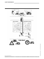
6. Mounting the antenna (Fig. 6)
Install the mast according to the instructions of the
mast manufacturer. For installation in caravans or
mobile homes, the Sat jointed mast HDM 140 can be
used. For installation on a truck, use the HDM 141.
Please use the Sat jointed mast tripod HDS 150 for
setting up the antenna on the ground.
If you wish to convert your terrestrial reception system
composed of the HD 35 and the Shapeg mast HDM
135 to a satellite reception system, please use the
jointed mast HDM 143.
7KHURRIIHHGWKURXJKDQGWKH¿[LQJFRQVROHRIWKH
HDM 135 can remain in place.
These masts allow an easy and quick alignment of the
antenna from the interior of the vehicle.
Detailed mounting instructions are supplied with the
mast.
:KHQPRXQWLQJWKHPDVWVRU6DWMRLQWHGPDVWWULSRG
proceed as follows:
1. Prepare the joint of the mast as shown in Fig. 6.
2. Place the antenna onto the joint as far as possible.
3. Fasten the antenna with the clamp,
torque for the two M 6 screws: M = 6.5 + 1 Nm.

935.2018/H/0806/4.12e
7. Connecting the cable
7.1 Connecting the cable to the antenna
(Abb. 7)
1. Loosen the two milled screws and remove the LNB
cover.
2. Connect the F-plug as shown.
3. Connect the cable to the LNB.
4. Now press the cable (outer diameter 6.8 mm) into
the cable support. If you use the thinner cable
(e.g. for Sat jointed masts HDM xxx with integrated
cables), fi rst put the supplied sleeve on the cable in
order to compensate the diameter.
5. Replace the LNB cover.
7.2 Connecting the cable to the receiver
(Fig. 8)
• Mount a F-connector to the end of the cable pointing
to the receiver. Cable and connector preparation
according to Fig. 7.
Note:
If the receiver is an older model; it may be necessary
to fi x to the cable an IEC angle plug. The plug is in the
scope of delivery of the connection cable HDK 80.
• To connect the BAS 60 and the receiver, the cable is
to be plugged to the „IF IN“ at the rear of the recei-
ver.
8. Adjusting the satellite receiver
• For TV sets with Scart connector:
Connect the TV set and the satellite receiver with the aid of the Audio/Video cable. Select on your TV set the
program position „AV“.
Note:
• The digital receivers UFS 601si, UFD 170 and UFS 740sw are designed for connection to TV sets with a Scart
connector.
• Switch the basic setting of the receiver from „22 kHz“ to the position „High/Low“.
• Detailed information for modifying the basic setting is found in the operating instructions for the receivers.
• For tuning the satellite receiver, select the desired program.
The satellite receiver is pre-programmed at the factory (see the program table of the satellite receiver).
Braiding overturned
sleeve (optional)
Fig. 7
Rear panel Receiver example (Partial view)
Fig. 8

935.2018/H/0806/5.12e
9. Aligning the satellite reception system
(Fig. 9)
9.1 Prerequisites
• The antenna must have an imaginary „visibility“ of the
satellite (the visibility must not be obstructed by trees,
buildings, etc.) towards the south at an angle of 15° to
55° relative to the horizon.
• The vehicle has to be positioned horizontally.
The antenna must be in the driving position.
9.2 Alignment procedure for the use of Sat
jointed mast
1. Loosen the cross grip screw of the mast console and
the cone nut on the roof feed-through.
Slide the antenna mast (HDM 140, HDM 143) from its
lowered position at least 13 cm up, in order to avoid
that the antenna collides with the roof when it is turned
around.
2. Elevation adjustment
• Switch to the program position 1 on the receiver.
This program position is assigned to the program
ARD at ASTRA 19,2° East for Kathrein receivers and
for most of the other receivers, which are on the
market in Germany.
• The antenna must be aligned to the south. Turn
the crank handle of the jointed mast clockwise until
the antenna has reached the elevation position requi-
red for the reception site. The number of the neces-
sary rotations can be gathered from the Azimut/Ele-
vation table or the graph on page 12.
3. Setting the Azimuth
You have aligned the antenna to the south, as descri-
bed under point 2, „Elevation adjustment“. Turn the
antenna mast slowly clockwise or counter-clockwise
until you see a picture on the TV screen.
The antenna is now roughly aligned.
4. Optimising the alignment
The picture quality can be optimised by fi ne adjustment
of the elevation and azimuth angle.
5. After the alignment is fi nished, do not forget to screw
on the cross grip screw on the mast console and the
cone nut on the roof feed-through.
6. A graph for quick alignment of the antenna is found on
page 12.
Advice: Put the user guides in a clear plastic folder and fasten the folder to the door of a wardrobe ensuring they
are at hand whenever they are needed.
9.3 Alignment procedure for use of Sat
jointed mast tripod
• The antenna must be aligned to the south.
1.Elevation adjustment
Loosen the cross grip screw on the joint and tip
the antenna to an elevation of about 30°.
2.Setting the azimuth
Loosen the cross grip screw on the shaft of the
joint and turn the antenna to the left and the
right (Azimuth) until you see a picture on the TV
screen.
This setting may have to be carried out with a
second person, if you cannot see the television
screen.
Optimise the picture quality by fi ne tuning the
elevation and azimuth.
Observe the instructions below.
Tighten both cross grip screw and lay the cable
in such a way, that nobody can stumble over it
and injure themselves.
Instructions for alignment with digital receivers
The signal quality is displayed in the menu “Installation & Set-
tings”, „TV Reception & Channel Search“ and „Signal Recep-
tion“ (example UFS 601si). In combination with UFD 170 and
HDP 171, the antenna is automatically aligned to receive the
signals in optimal strength and quality.

935.2018/H/0806/6.12e
10. Maintenance
• The BAS 60 as well as the mounting accessories (HDM jointed masts and tripod) are maintenance-free.
Attention!
Before your start the journey, make sure that no parts of the antenna system are loose. Parts that are loose must
be fastened.
• Cleaning
For cleaning use clear water and the cleaning agents usual for motor vehicles.
Do not use cleaning agents containing acetone, celluse thinner, benzene, etc. since these can damage the an-
tenna.
Do not use high pressure steam cleaners.
11. Information on waste disposal
Electronic equipment is not household waste - in accordance with directive 2002/96/EC
OF THE EUROPEAN PARLIAMENT AND THE COUNCIL of 27th January 2003 on used
electrical and electronic equipment, it must be disposed of properly.
$WWKHHQGRILWVVHUYLFHOLIHWDNHWKLVXQLWIRUGLVSRVDODWDUHOHYDQWRI¿FLDOFROOHFWLRQ
point.
12. Operating failures
Defect Possible causes
- No picture
- Freeze frame for digital reception
- Obstacle between antenna and satellite
- The reception site is outside the coverage area
- TV set or receiver faulty or no power
- The plug of the antenna cable is loose
- Bad picture quality
- Block formation for digital reception
- Obstacle between antenna and the satellite
/HDYHVVQRZRULFHFRYHUWKHDQWHQQD
- The reception site is in a fringe area of the footprints. Perhaps you can
¿QGDPRUHSRZHUIXOVDWHOOLWHSURJUDP
- The plug of the antenna cable is loose
Note!
,QWKHHYHQWWKDW\RXFRXOGQRW¿QGWKHFDXVHDQGZHUHXQDEOHWRUHPHG\WKHGHIHFWFRQWDFW\RXUVSHFLDOLVWGHD
ler or our service centre. Do not open the antenna!
The address of our service centre (for Germany):
ESC Elektronik Service Chiemgau GmbH
Bahnhofstraße 108
83224 Grassau
Tel. (0 86 41) 95 45-0
Fax (0 86 41) 95 45 35 and 95 45 36
Internet: www.esc-kathrein.de

935.2018/H/0806/7.12e
13. Technical data and dimensions
Type BAS 60
Order no. 216195
Usability for mobile application
Mounting HDP 171, HDM 140, 141, 143, HDS 150
Reception range GHz 10.70-12.75
/1%QRLVH¿JXUH dB Typ. 0.8
Gain dB > 50
Half power beam width ° < 3
1)
/1% 1 output switchable
H/V, high/low
Switch-over
low-band
high-band
kHz 0
22
Output frequency MHz 950-1950/1100-2150
Oscillator frequency GHz 9.75/10.6
Figure of merit (G/T)
11.3/12.5 GHz
dB/K 13.3/13.7
/1%VXSSO\
voltage
V vert.: 11.5-14.0
hor.: 16.0-19.0
Current drain max. mA 160
:LQGORDG N 240
2)
Adjustment range
Elevation
Azimuth
0-90 (HDM xxx und HDS 150), 10-90 (HDP 171)
360
:HLJKW kg 5.4
1) At mid-band
2) At a dynamic pressure of 800 N/m
2
according to DIN EN 50083-1 or VDE 0855 and antenna in vertical position.
Fig. 10
Fig. 11
Fig. 12

935.2018/H/0806/8.12e
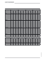
14. Azimuth/Elevation table
For the fi rst approach towards the satellites EUTELSAT II F2 10° and EUTELSAT II F3 16° you can take the values
for EUTELSAT II F1 13° shown in the table.
The values in column „U“ refer to the crank handle rotations in connection with the mobile antenna BAS 60.
ASTRA 19,2° East EUTELSAT 13,0° East Atlantic Bird 5,0° West ASTRA 28,2° East
Germany Az El U Az El U Az El U Az El U
Bad Reichenhall 171,5 34,9 4 3/4 179,9 35,2 4 3/4 203,6 32,5 5 1/4 159,7 33,20 5
Berlin 172,7 29,7 5 1/4 180,5 30,0 5 1/4 202,8 27,6 5 1/4 161,6 28,4 5 1/4
Bremen 167,1 28,6 5 1/4 174,8 29,2 5 1/4 197,1 28,0 5 1/4 156,3 26,8 5 1/2
Cottbus 173,8 30,6 5 181,7 30,8 5 204,1 28,1 5 1/4 162,5 29,4 5 1/4
Dortmund 165,1 30,0 5 1/4 172,9 30,8 5 195,8 29,9 5 1/4 154,2 27,9 5 1/4
Dresden 173,0 31,3 5 180,9 31,6 5 203,6 28,9 5 1/4 161,6 30 5 1/4
Emden 165,2 28,1 5 1/4 172,8 28,8 5 1/4 195,1 28,0 5 1/4 154,9 26,2 5 1/2
Erfurt 169,5 31,1 5 1/2 175,7 27,4 5 1/2 197,5 26,2 5 1/2 158,3 29,4 5 1/4
Flensburg 168,1 26,9 5 1/2 175,7 27,4 5 1/2 197,5 26,2 5 1/2 157,4 25,3 5 1/2
Frankfurt/Main 166,4 31,7 5 174,4 32,4 5 197,6 31,1 5 155,2 29,6 5 1/4
Freiburg 164,9 33,8 4 3/4 173,1 34,7 4 3/4 197,0 33,5 4 3/4 153,5 31,4 5
Greifswald 172,8 28,0 5 1/4 180,5 28,3 5 1/4 202,3 26,0 5 1/2 161,9 26,8 5 1/2
Hamburg 168,6 28,3 5 1/4 176,3 28,8 5 1/4 198,4 27,3 5 1/2 157,7 26,6 5 1/2
Hannover 168,2 29,5 5 1/4 175,9 30,1 5 1/4 198,4 28,6 5 1/4 157,2 27,7 5 1/4
Kassel 167,6 30,6 5 175,4 31,2 5 198,3 29,7 5 1/4 156,5 28,7 5 1/4
Kiel 168,89 27,47 5 1/2 176,47 27,97 5 1/4 198,42 26,50 5 1/2 158,1 25,9 5 1/2
Koblenz 164,94 31,27 5 172,87 32,10 5 196,07 31,12 5 153,9 29,1 5 1/4
Leipzig 171,27 30,93 5 179,19 31,28 5 201,84 29,05 5 1/4 160 29,4 5 1/4
Magdeburg 170,45 29,98 5 1/4 178,27 30,39 5 1/4 200,73 28,41 5 1/4 159,3 28,4 5 1/4
M‘gladbach 163,81 30,19 5 1/4 171,62 31,09 5 194,57 30,42 5 1/4 152,9 27,9 5 1/4
München 169,80 34,24 4 3/4 178,08 34,72 4 3/4 201,77 32,45 5 158,1 32,4 5
Neubrandenburg 172,62 28,60 5 1/4 180,31 28,85 5 1/4 202,29 26,59 5 1/2 161,6 27,3 5 1/2
Nürnberg 169,33 32,76 5 177,43 33,27 5 200,74 31,25 5 157,9 31 5
Osnabrück 166,01 29,32 5 1/4 173,75 30,04 5 1/4 196,33 28,99 5 1/4 155,1 27,3 5 1/2
Passau 172,37 33,99 4 3/4 180,62 34,26 4 3/4 204,01 31,48 5 160,7 32,5 5
Pirmasens 164,83 32,48 5 172,88 33,33 5 196,45 32,29 5 153,6 30,2 5 1/4
Plauen 170,87 31,77 5 178,88 32,15 5 201,78 29,91 5 1/4 159,5 30,2 5 1/4
Ravensburg 167,13 34,45 4 3/4 175,41 35,04 4 3/4 199,38 33,33 5 155,6 32,2 5
Regensburg 170,63 33,36 5 178,81 33,77 4 3/4 202,17 31,41 5 159,1 31,7 5
Rostock 171,30 27,94 5 1/4 178,93 28,27 5 1/4 200,84 26,32 5 1/2 160,4 26,6 5 1/2
Stuttgart 166,79 33,18 5 174,93 33,89 4 3/4 198,57 32,36 5 155,4 31,1 5
Trier 163,72 31,72 5 171,68 32,65 5 195,10 31,90 5 152,6 29,4 5 1/4
Ulm 167,13 33,75 4 3/4 175,95 34,39 4 3/4 199,68 32,60 5 156,2 31,7 5
La page est en cours de chargement...
La page est en cours de chargement...
La page est en cours de chargement...
La page est en cours de chargement...
La page est en cours de chargement...
La page est en cours de chargement...
La page est en cours de chargement...
La page est en cours de chargement...
La page est en cours de chargement...
La page est en cours de chargement...
La page est en cours de chargement...
La page est en cours de chargement...
La page est en cours de chargement...
La page est en cours de chargement...
La page est en cours de chargement...
La page est en cours de chargement...
La page est en cours de chargement...
La page est en cours de chargement...
La page est en cours de chargement...
La page est en cours de chargement...
La page est en cours de chargement...
La page est en cours de chargement...
La page est en cours de chargement...
La page est en cours de chargement...
La page est en cours de chargement...
La page est en cours de chargement...
La page est en cours de chargement...
La page est en cours de chargement...
-
 1
1
-
 2
2
-
 3
3
-
 4
4
-
 5
5
-
 6
6
-
 7
7
-
 8
8
-
 9
9
-
 10
10
-
 11
11
-
 12
12
-
 13
13
-
 14
14
-
 15
15
-
 16
16
-
 17
17
-
 18
18
-
 19
19
-
 20
20
-
 21
21
-
 22
22
-
 23
23
-
 24
24
-
 25
25
-
 26
26
-
 27
27
-
 28
28
-
 29
29
-
 30
30
-
 31
31
-
 32
32
-
 33
33
-
 34
34
-
 35
35
-
 36
36
-
 37
37
-
 38
38
-
 39
39
-
 40
40
-
 41
41
-
 42
42
-
 43
43
-
 44
44
-
 45
45
-
 46
46
-
 47
47
-
 48
48


Kathrein BAS 60 Mode d'emploi
- Catégorie
- Antennes satellites
- Taper
- Mode d'emploi
Documents connexes
-
Kathrein BAS 60 Manuel utilisateur
-
Kathrein HDP 160 Manuel utilisateur
-
-
-
-
-
-
-
-
Autres documents
-
Hama 00047454 Le manuel du propriétaire
-
Hama 00047458 Le manuel du propriétaire
-
Megasat Caravanman 65/85 Manuel utilisateur
-
-
-
Kärcher HDS-C 8 15-E Le manuel du propriétaire
-
LG 88BH7D Le manuel du propriétaire
-