
P
U
LL
O
N
P
U
S
H
O
F
F
R
E
S
E
T
OU
T
LE
T
S
(6151)COVER
60
45
3
0
1
5
30
4
5
60

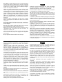
DO NOT attempt to assemble or operate your Router
Table until you have read the safety instructions in this
section. Safety items throughout this manual are labeled
with WARNING or CAUTION.
Warning means that failure to follow this
safety statement may result in extensive
product damage, serious persoe0 -1.5set this TwrTc280957 TCausecting means that failure to follow t hissafety statement may result minle or

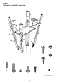
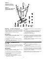
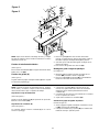
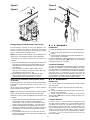
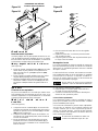
Attach Height Adjustable Legs
(See Figure 1.)
1. Place router table top (A) upside-down on
a flat surface.Take care not to scratch the
table top surface.
2. Attach legs (Q) securely to table top with
16 screws (FF). Use a #3 Phillips screw-
driver to keep from stripping the screw
heads.
3. Decide what height you want your Router
Table to be from the floor.
4. With the “foot” of short leg (P) pointing
upward, align 2 holes in short leg with 2
holes in long leg at appropriate height.
NOTE: Short leg (P) mounts inside of long
leg (Q).
5. Thread 2 carriage bolts (AA) through the
holes in both leg members. Assemble 1
washer (EE) and 1 nut (DD) to each
screw.Tighten nuts.
6. Attach the three remaining legs in the
same manner. In order to obtain the same
height above the floor, use the same hole
position as the first leg you attached.
7. Insert and attach 4 molded “shoes” (Z) to
feet.
8. Level the table by adjusting the short legs
(P) within the slotted mounting holes on
the long legs (Q).
Attach Tool Tray
(See Figure 1.)
1. Align holes in legs to holes in corners of
tool tray.
2. Use 8 carriage bolts (AA), 8 washers
(EE), and 8 nuts (DD) to attach the tray.
Attach Optional Second Shelf
(See Figure 1.)
1. Place shelf corners on each one of the
“brackets” that protrude from the height
adjustable legs (shelf board not provided).
2. Use screws (not provided) to attach the
shelf.
NOTE: After you have completed the basic
assembly, including legs, and shelf, place the
router table right-side up on work surface or floor.
Unpacking and Checking
Contents
Separate all parts from the packing materials
and check them against the “Parts List” in this
manual. Make sure all parts are accounted for
before discarding any of the packing material.
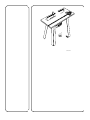
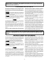
Introduction
Versatile, durable, sensibly priced – wolfcraft
®
offers the finest quality router tables.
Router table features include:
●
a unitized fence that allows mounting of
boards up to 8"
●
a front-mounted, safety keyed power
switch with two 120-volt receptacles
●
Laminate top that provides a smooth,
clean routing surface
●
reinforced steel brackets to assure
flatness
●
a security guard/dust collector
●
a connection for a wet/dry vac for efficient
dust collection
●
fence-mounted feather boards
The Model 6151 Router Table also has height
adjustable legs that provide floor mounting
from 32" to 38", a steel storage tray, and a
number of other handy, innovative features.
We are sure you will find your wolfcraft router
table a valuable addition to your workshop.
NOTE: This manual covers assembly instruc-
tions, setup, operation, and parts lists for
Model 6151 Router Table.
Assembling Your Router
Table
Tools Required
#2 and #3 Phillips Screwdriver
Hammer
Adjustable Wrench
3

4
Figure 1
Assembly for Model 6151 Router Table
(6151)EV-BOTTOM LONG LEG
EE
EE
DD
Z
P
O
AA
FF
AA
AA
Q
DD
FF
FF
Optional
Second Shelf
(not provided)
EE
HH
AA
BB
DD

5
GG
H
MM
(6151)EV-TOP
G1
G2
G3
G4

6
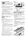
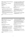
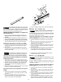
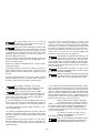
Assemble Plastic Miter Guide
(See Figure 3.)
1. Assemble miter gauge by threading car-
riage bolt (BB) through miter bar (S).
2. Place washer (II) and knob (N) on end of
carriage bolt.Tighten knob.
Figure 3
Vibrations from normal routing
may loosen the washer and bolt
that hold the rod to the plate. Occasionally
check these components to make sure they
are tight.
Assemble Jointing Fence to Router Table
Fence
1. Using the slots on the fence as guides,
slide the jointing fence (C) part way into
the router table fence (B).
2. Using the adjusting knob (N), washer (II),
and bolt (CC), assemble the jointing fence
to the router table fence.
3. Slide the jointing fence into the router
table fence as far as you can. Tighten the
adjusting knob.
Attach Security Guard to Fence
1. Position the two holes on the security
guard so that they align with the two holes
on the fence.See Figure 4.
WARNING
GUIDE1
60
45
30
15
0
15
30
45
60
II
BB
S
N
E
2. Slide pivot pin (V) through holes in fence
and security guard. Secure by tapping on
two cap nuts (LL).
3. Test moveability by moving security guard
up and down.
Figure 4
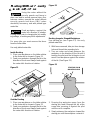
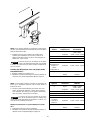
Mounting the Router
Always remove router bits and
unplug router before mounting
to router table.
The table will accept routers with bases up to
7" in diameter. There are two methods for
attaching routers to router table:
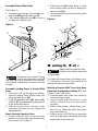
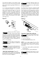
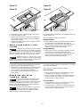
Mounting Routers With Three Hole Base
Plate Hole Configuration Pattern “E.” (See
Figures 5 and 7 with chart.)
1. Remove router base plate from router by
removing three screws.
2. Loosen knobs and slide fences so that
notches in fences line up to clear mount-
ing holes.
3. While holding router upside down, posi-
tion it to the underside within the center
ring of the table top.
4. Rotate router until the three mounting
holes in router base line up with the three
larger holes in the table top.
CAUTION
WOLF113-34
C
CC
B
LL
K
LL
L
L
K
J
N
II
F

7
NOTE: For ease of use, position the router so
the ON-OFF switch is accessible from the
front of the table.
5. Insert three router base plate screws pre-
viously removed (T) through holes in table
top and into router mounting holes.
Tighten securely.
Make sure the screws from
router base plate are long
enough to mount router securely. Replace if
necessary.
Figure 5
PULL ON
PUSH OFF
RESET
O
U
T
L
E
T
S
WOLF113-8
F
CAUTION
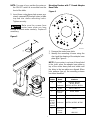
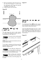
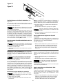
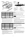
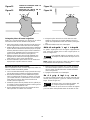
Mounting Routers with 7" Round Adaptor
Base Plate
Figure 6
1. Remove the router base plate.
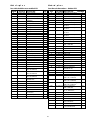
2. Identify the mounting scheme using the
chart and the drawing of the adaptor base
plate (I) in Figure 6.
NOTE: If your router is not one of those listed
in the chart, place the adaptor base plate on
top of the router base plate and rotate until
the holes in the two plates are aligned. When
hole patterns line up, the mounting scheme
has been identified.
Hole Router Model
Pattern Brand Numbers
A Ryobi #R160K, #R160V,
#R165, #R180
Craftsman #27500, #27510, #27511
B Ryobi #R175, #RE175
C Black and #7600, #7604
Decker
D Porter Cable #690, #6931
Mount Skil #1823, #1835, #1845-02
Directly
to Table Craftsman #17504, #17505, #17506
or Use
Pattern E
F Black and #7612
Decker
Dewalt #DW 610
A
A
C
C
C
C
D
D
I
D
E
E
E
F
F
F
H
H
H
AB
AB
WOLF113-3

8
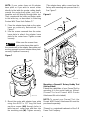
NOTE: If your router does not fit adaptor
base plate or if you wish to mount router
directly to the table for greater cutting depth,
remove the router base plate, use it as a
template and drill directly through table top.
Then, countersink the holes and fasten router
to the table top, as described in Attaching
Routers With Three Hole Pattern “E.”
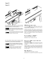
3. Place the adaptor base plate on the router
base as previously determined. See
Figure 7.
4. Use the screws removed from the router
base plate to attach the adaptor base
plate to the router base. Tighten screws
securely.
Make sure the screws from
your router base plate match
the countersink in the adaptor base plate and
are long enough to mount adaptor base plate
securely. Replace if necessary.
Figure 7
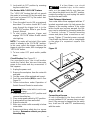
5. Mount the router with adaptor base plate
using the #10-32 x 1/2" long flat head
machine screws (HH) through holes in
table top and router base and then into
the mounting nuts (W). Tighten securely.
WOLF113-10
W
I
HH
CAUTION
(The adaptor base plate comes from the
factory with mounting nuts pressed into it.)
See Figure 7.
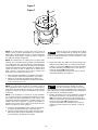
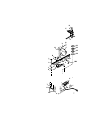
Figure 8
Mounting a Dremel®* Rotary Hobby Tool
(Not Included)
Extend the capabilities of your Dremel Tool by
mounting it to the router table as follows:
(Dremel Tool and Dremel #330 Router
Attachment Kit not included):
NOTE: To mount your Dremel Tool, the
Dremel #330 Router Attachment Kit must be
purchased separately.
*Dremel is a registered trademark of the S-B
Power Tool Company.
P
U
L
L
O
N
P
U
S
H
O
F
F
R
E
S
E
T
O
U
T
L
E
T
S
WOLF113-28
F

9
Figure 9
1. Attach the Dremel
®
Rotary Hobby Tool to
the Tool Holder Assembly from the Dremel
#330 Router Attachment Kit as stated in
the Router Attachment Kit Owner’s
Manual.See Figure 9.
2. Secure the hobby tool assembly to the
router table using the Bracket Mounting
Screws from the #330 Router Attachment
Kit.
3. The solid insert that comes with this
router table can be drilled out off center to
give you better small workpiece support.
Switch Box
Introduction
A conveniently located Switch Box allows the
operator to:
• turn the router ON and OFF from the front
of the table
• simultaneously operate other devices
such as a light or a vacuum
DREMEL
®
O
N
OFF
WOLF113-24
It also features a resettable, internal circuit
breaker (NN, Figure 12) that protects your
equipment against overloads.
Electrical Hookup
Proper grounding diverts potentially danger-
ous electricity away from the operator. The
switch box is intended for use with a three-
prong, grounded outlet. (See Figure 10.) The
switch box’s electrical cord features an equip-
ment-grounding connector and a grounding
plug. Insert the plug into an accommodating
outlet that conforms to all local electrical
codes and the National Electric Code (NEC).
DO NOT modify the plug. If it
does not fit correctly, a qualified
electrician must install a compatible outlet.
Avoid the risk of electrical
shock. NEVER connect the
equipment grounding connector (green wire)
to a “hot” electrical terminal. When repairing
or replacing the electric plug or cord, DO
NOT connect the grounding connector to a
“hot” electrical terminal.
Figure 10
Consult a qualified electrician if you do not
understand the grounding procedures, or if
you are not sure whether the switch box is
correctly grounded.
Damaged and/or worn cords must be
repaired or replaced immediately.
Extension cords must be three-wire, 14
gauge or larger, with three-prong “male”
plugs, and three hole “female” receptacles
fabricated to accept the tool’s plug.
WOLF108-13
WARNING
WARNING

10
The electrical outlets on the bottom of the
switch box accept three-prong grounded
plugs and the two-prong plugs of double insu-
lated tools.
If a correctly grounded outlet is unavailable,
use a temporary adapter to connect the
switch box’s three-prong plug to a two-hole
receptacle. Make use of the temporary
adapter only until a qualified electrician
installs a correctly grounded, three-prong out-
let. The green rigid lug or grounding wire
MUST connect to the ground on the outlet.
(See Figure 11.)
Figure 11
RISK OF ELECTRIC SHOCK.
DO NOT touch prongs when
inserting or removing plug from outlet.
Improper grounding can produce potentially
hazardous electrical discharges that can, in
turn, cause serious injury or death – especial-
ly in wet conditions, such as a basement, out-
side, or near plumbing.
DO NOT attach a 3-way plug or
any other adapter to outlets on
bottom of switch box.
Only use the switch box when it
is properly assembled to the
router table AND when the router is properly
attached to the router table.
Switch Box Familiarization (Figure 12)
The purpose of this section is to familiarize
the user with the operation of the switch box
BEFORE the router is plugged in.
WARNING
WARNING
WARNING
WOLF113-14
DO NOT plug the router in at
this time. An ON switch will
start and an unprepared user could possibly
be seriously injured.
The Switch Box also features a Safety Key (Y)
that prevents the router’s ON/OFF switch
from being turned ON inadvertently. Removal
of the safety key disables the switch box by
locking the switch in the OFF position. Strike
the switch paddle with your hand to turn the
router OFF in an emergency situation. Please
note paddle switch positions and reset button
(NN) at this time.
Figure 12
Operation of Switch Box and Router
Make sure router switch is OFF
and switch box is OFF BE-
FORE proceeding.
1. Insert the safety key.
2. Place router power switch to ON.
NOTE: If your router requires the use of the
switch trigger and “LOCK-ON” button, refer to
your Router Owner’s Manual for operating
instructions.
3. Insert finger under paddle and pull switch
to ON position.
4. To turn router OFF push paddle down.
Router bit must come to a com-
plete stop before leaving router
table unattended.
WARNING
WARNING
PULL ON
PUSH OFF
RESET
OUTLETS
WOLF113-11
NN
Y
WARNING

11
5. Lock switch to OFF position by removing
key from switch box.
For Routers With “LOCK-ON” Feature
The “LOCK-ON” feature that will not permit
the router to be turned ON by the switch box,
but it can be turned OFF by the switch box.
Operate as follows:
1. Place the switch box to ON as previously
described. The router should NOT start
even though the trigger lock is in the
“LOCK-ON” position. Refer to your Router
Owner’s Manual.
2. To start router, depress trigger and
engage “LOCK-ON” button. Router should
start right up.
NOTE: The router will not start if the router
switch is already in the “LOCK-ON” position.
In this case, unlock the trigger, depress the
trigger to start the router, then re-engage the
“LOCK-ON” button.
3. To turn router OFF push switch paddle
down.
Circuit Breaker (See Figure 12.)
If an overload occurs, the circuit breaker
inside the Switch Box trips and interrupts
power to the router and any accessories. If
this happens:
1. Unplug the power cord.
2. Remove the workpiece from the router bit
and table.
3. Find the cause of the overload and correct.
4. Push the reset button (NN) to reset it. See
Figure 12.
5. Follow instructions under Operation of
Switch Box and Router to reset router.
When router table is not in use
always:
1. Place the switch box in OFF position and
remove the safety key.
2. Place router power switch to OFF position.
3. Unplug switch box from wall outlet.
4. Remove router bit.
5. Make sure router collet assembly is below
router table.
6. Remove and place safety key in a secure
location. Remember where you place
the safety key.
WARNING
If a fuse blows, or a circuit
breaker trips, or the router
stalls, or if the power fails for any other rea-
son, place the switch box in the OFF position,
remove the safety key, and unplug the switch
box from the wall outlet.
Table Flatness Adjustment
Your router table comes equipped with two “L”
brackets mounted under it to help ensure the
flatness of the working surface. If the router
table should ever become warped, the flat-
ness can be adjusted by shimming under the
“L” bracket. Loosen “L” bracket mounting
screws and place shims or washers as nec-
essary. Tighten “L” bracket screws securely.
Check table top flatness with a straightedge
or the edge of a carpenter’s square. See
Figure 13.
Figure 13
Operation
Connecting a Vacuum
A hole is provided in the fence which will
accept standard 2-1/4" vacuum hose connec-
tions. If the vacuum is plugged into the switch
box, it will turn ON and OFF simultaneously
with the router.
WOLF113-27
WARNING

12
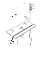
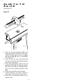
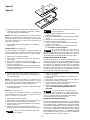
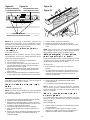
Assemble Fence to the
Router Table
(See Figure 14.)
Figure 14
1. Place the threaded stampings (H) in the
deepest machined cut-outs on the under-
side of the table top and secure in position
with fence guide (H) and 4 screws (GG).
(See Figure 14.)
2. Place the fence on the router table with
the front of the fence (flat edge) facing the
front of the router table.
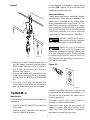
3. Insert knob (J) threaded end into the slot
provided in the table, through the washer
(L) and then through the threaded stamp-
ings in the fence guide mounted on the
table.
4. Secure by turning the knob clockwise.
5. Follow numbers 1 through 4 above to
attach other side of fence to router table.
6. When fence is in desired location for cut,
tighten knobs.
WOLF113-30
GG
H
P
U
L
L
O
N
P
U
S
H
O
F
F
R
E
S
E
T
O
U
T
L
E
T
S

Insert Use
1. Select correct insert for the router bit and
your application.
2. To assemble to router table, press the
insert into the hole in the table, applying
pressure to all sides equally. This assures
that insert snaps into place.
3. Remove an insert by placing your finger
into the hole in the center. With light pres-
sure, pull up on the insert.
NOTE: Remove the router bit from the router
before attempting to remove an insert..
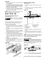
Router Table Use
Setting Depth/Height of the Cut
(See Figure 16.)
Make sure router is unplugged
before starting depth/height
adjustment.
Using scrap board that is smooth and true is
recommended for making this adjustment.
Follow the instructions below.
1. At the end of the board, use a soft pencil
to mark line #1.This indicates the depth of
the cut.
2. Then mark line #2, indicating the height of
the cut.
3. Place your board so that it is snuggly
against the fence face. The end with lines
#1 and #2 should be near the bit.
4. Untighten fence clamp knobs enough so
you can move the fence easily. Move
fence and board so that the board con-
tacts the outer edge of the router bit at
line #1.
5. Tighten down clamping knobs.
6. Adjust router height so the cutting edge of
the bit contacts line #2.
7. Make sure the bit is securely tightened to
the chuck.
Figure 16
WOLF113-35
PENCIL LINE #2
PENCIL LINE #1
WARNING
Beading and Edge Cutting
(See Figure 17.)
1. Loosen the knobs that hold the fence in
place.
2. Locate the fence to the desired cutting
depth (3, Figure 17).
Figure 17
1. Table Top 5. Successive Cut
2. Fence 6. Depth of Cut
3. Cutting Depth 7. Router Bit
4. Workpiece
3. Tighten the knobs, securing the fence in
place.
4. Swing the safety shield over the router bit.
5. Your router/router table is now ready for
use.
NOTE: Remember: always feed the workpiece
against router bit’s direction of rotation.Test on
scrap wood before making final cuts.
Using Piloted Bits
To help reduce the chance of
injury, make sure the fence is as
close as possible to the router bit pilot. Move
the fence back ONLY enough to permit the
pilot to control the depth of cut.
Figure 18
WOLF113-18
1
WARNING
WOLF113-17
1
2
3
4
7
5
6
13

Veining, Fluting, and Grooving
Feed workpiece against the
router bit’s direction of rotation.
Unplug router prior to changing the bit, modify-
ing settings, or making any other adjustments.
(See Figure 17.)
The edge of the workpiece that slides along
fence must be straight and true for best
results.(Use scrap to test settings.)
1. With the router bit set at the required
depth, place the fence behind the bit at a
distance determined by the previous cut.
Lower safety shield.
2. Secure both clamping knobs.
3. Slide the workpiece against the fence.
Adjust fence for subsequent cuts.
NOTE: For deep work, make successive cuts
until you reach the correct depth. To avoid
overloading router, remove waste material as
you go.
Using the Router as a
Jointer
(See Figures 16 and 19.)
NOTE: Make sure boards that are to be joint-
ed together are true and smooth. Also make
sure edges are prepared properly.
1. Position the fence to the desired depth of
the cut.
2. Tighten the fence knobs.
3. Securely tighten the router bit, and make
sure the router is properly assembled to
the router table as previously detailed in
this manual.
4. Place a straight edge against the jointer
offset.
5. Loosen the knob holding the jointer offset
in place.
6. Slide jointer offset out until straight edge
touches the outside diameter of the router
bit.
7. Tighten the jointer offset knob.
8. Swing the safety shield over the router bit.
9. Your router/router table is ready to use.
NOTE: Try a piece of scrap wood to check for
correct adjustment. When standing in front of
router table, feed work from right to left.
WARNING
Figure 19
Using Fence with Board
for Larger Workpieces
Four holes in the fence allow for mounting of a
8-inch high (maximum) board for safe and
secure routing of larger workpieces.
(See Figure 20.)
1. Attach board to fence with 4 woodscrews
(not provided).
2. Board can be notched out prior to routing
or router bit profile can be made in board
by driving board thru router bit.
3. Position the fence to the desired depth of
the cut.
4. Tighten the fence knobs.
5. Securely tighten the router bit, and make
sure the router is properly assembled to
the router table as previously detailed in
this manual.
6. Your router/router table is ready to rout
large workpieces.
Figure 20
WOLF113-53
PULL ON
PUSH OFF
RESET
OUTLETS
WOLF113-15
DEPTH OF CUT
FENCE KNOBS
JOINTER OFFSET
14

15
Routing Without Security
Guard and/or Fence
Using the router without the
security guards and fence in
place can lead to serious personal injury. Use
extreme caution: operate the router without
security guards and fence ONLY when
absolutely necessary, and with piloted type
router bits.
Feed workpiece against the
router bit’s direction of rotation.
Unplug router prior to changing the bit, modify-
ing settings, or making any other adjustments.
For many jobs you must remove the fence
from the router table.
Use only piloted router bits.
Inside Routing
1. Place your workpiece on the table relative
to the router bit as shown in Figure 21.
2. Feed your workpiece through the bit in the
direction of the arrow. Always feed against
the router bit’s direction of rotation.
Figure 21
Outside Routing
1. Place your workpiece on the table relative
to the router bit as shown in Figure 22.
2. Feed your workpiece through the bit in the
direction of the arrow. Always feed against
the router bit’s direction of rotation.
WOLF113-37
PULL ON
PUSH OFF
RESET
O
U
T
L
E
T
S
WARNING
WARNING
Figure 22
Routing Irregular Shaped Workpieces
Use starting pin (see Figure 23). Use only
piloted router bits.
1. With fence removed, take pin from storage
hole and thread into mounting hole.
2. Turn on router and slowly advance the
workpiece in the direction of the bit until it
touches the pilot and the bit begins to cut
wood. Feed workpiece against the rotation
of the bit. (See Figure 23.)
Figure 23
3. Drawing the workpiece away from the
starting pin, feed it through the bit, at the
same time pressing it against the pilot
until the cut is complete.
4. Slowly advance the workpiece toward the
starting pin until the workpiece contacts it.
STARTING PIN IN
MOUNTING HOLE
WOLF113-39
WOLF113-38
PULL ON
PUSH OFF
RESET

16
5. Move the workpiece away from the bit, at
the same time keeping it in contact with
the starting pin, until it clears the router bit
completely. (See Figure 24.)
6. Using the switch, turn off router.
Figure 24
Using the Miter Gauge
and Fence
The miter gauge can serve as extra support
for routing small workpieces and for ends of
long workpieces.(See Figure 25.)
You must use the security guard
when making cuts using the
miter gauge.
NOTE: Make sure fence and miter bar slot are
parallel before cutting.
To cut miters, unclamp knob that secures the
protractor head. Turn head up to 60° in either
direction.Retighten knob.
Do not allow any body part to
be in line with the router bit at
any time when the miter gauge is in use. Doing
so could lead to serious personal injury.
When making cuts using the
miter gauge, hold the workpiece
firmly against the fence, the miter gauge, and
the table.
WARNING
WARNING
WARNING
WOLF113-40
Figure 25
Using the Featherboard
Flaps
The featherboard flaps (MM) provide support
for the workpiece by holding it securely, which
helps minimize chatter and kickback.
Insert the featherboard flap into fence to hold
down workpieces. Holding pressure can be
varied by putting long or short end of flaps in
fence, or by varying the distance of flap end
from the fence.
Figure 26
PU
LL O
N
PU
SH OF
F
R
ESET

Specifications
Work Space: 446 Square inches
Dimensions: 14"W x 31-1/2"L x 32" to 38"H
GG
H
MM
G1
G2
G3
G4
P
U
L
L
O
N
P
U
S
H
O
F
F
R
E
S
E
T
O
U
T
L
E
T
S
6
0
4
5
30
1
5
0
1
5
3
0
4
5
6
0
BB
S
N
II
E
T
GG
X
U
C
CC
B
LL
V
LL
L
L
K
J
N
II
F
GG
FF
GG
D
R
A
I
W
HH
EE
EE
DD
Z
P
O
AA
FF
FF
FF
AA
AA
Q
DD
Optional
Second Shelf
(not provided)
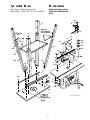
(6151 P/L)EXPLODED VIEW
17
Parts Lists
Exploded view and list
For Router Table Model
6151

Parts Lists
For Router Table Model
6151
KEY NO. PART NO. DESCRIPTION QTY.
A 119 900 809 Laminate Table Top 1
B 116 620 247 Fence 1
C 116 620 248 Jointing Fence 1
D 116 620 258 Switch Bracket 1
E 116 600 134 Protractor Head 1
F 116 680 216 Security Guard 1
G1 116 680 217 Table Top Insert 1
G2 116 680 218 Table Top Insert 1
G3 116 680 219 Table Top Insert 1
G4 116 680 220 Table Top Insert 1
H 116 600 135 Threaded Stamping 2
I 116 600 242 Adapter Plate 1
J 116 670 014 Knob 2
K 116 710 020 Stop Nut (M 6 DIN 985) 2
L 116 730 132 Washer (6,4 DIN 9021) 4
M 117 220 183 Thread Bushing (M6) 1
N 116 670 012 Knob Nut 2
O 117 020 213 Shelf 1
P 117 020 211 Leg, Short 4
Q 117 020 212 Leg, Long 4
R 117 020 219 L-Bracket 2
S 117 040 133 Miter Bar 1
T 117 101 132 Threaded Flat Stamping 2
U 117 220 181 Starting Pin 1
V 117 220 182 Pivot Pin 1
W 116 730 128 Hex Nut (Zoll #10-32) 3
X 117 920 107 Switch 1
Y 116 620 275 Safety Key 1
Z 116 680 223 Rubber Shoe 4
AA 116 700 065 Carriage Bolt (M 6 X 16 DIN 603) 24
BB 116 700 066 Carriage Bolt (M 6 X 30 DIN 603) 1
CC 116 700 068 Hex Head Bolt (M 6 X 30 DIN 931) 1
DD 116 730 125 Hex Nut (M 6 DIN 934) 24
EE 116 730 133 Toothhead Washer (6, 4 DIN 6797) 24
FF 116 710 098 Wood Screw 24
GG 116 700 076 Wood Screw 7
HH 116 700 077 Countersink Screw 3
II 116 730 132 Washer (6,4 DIN 9021) 2
KK 116 310 463 Instruction Manual (not shown) 1
LL 116 730 135 Capnut 2
MM 116 620 257 Feather Boards Flaps 3
18

AVERTISSEMENT: LE NON RESPECT DES CONSIGNES DE SÉCURITÉ, DES INSTRUCTIONS DE FONCTION-
NEMENT ET DES AVERTISSEMENTS CONCERNANT L'UTILISATION DE CET OUTIL RISQUE D'ENTRAÎNER DE
GRAVES BLESSURES CORPORELLES.
CONSIGNES DE SECURITE
NE PAS tenter d’assembler ou de faire fonctionner la table
de défonceuse avant d’avoir bien lu les consignes de sécu-
rité qui suivent. Les éléments de sécurité contenus dans ce
guide sont signalés par les indications AVERTISSEMENT et
ATTENTION.
Cette indication signifie que le non respect de
la consigne de sécurité risque d’endommager
sérieusement le produit et de provoquer des blessures cor-
porelles graves, voire mortelles.
Cette indication signifie que le non respect de
la consigne de sécurité risque d’entraîner des
blessures corporelles légères ou modérées, et d’endom-
mager légèrement le matériel ou les équipements.
Lire attentivement le guide d’utilisation de l’outil motorisé.
Bien comprendre son application et ses limites ainsi que les
dangers potentiels spécifiques à l’outil.
Mettre à la terre tous les outils (sauf en cas de double isola-
tion). L’outil est équipé d’un cordon agréé à trois conduc-
teurs et d’une fiche de terre à trois broches qui s’adapte à la
prise de terre appropriée. Le conducteur vert du cordon est
le fil de terre. NE JAMAIS relier le fil vert à une borne sous
tension.
Utiliser des cordons appropriés. NE JAMAIS transporter
l’outil par le cordon et ne jamais tirer sur le cordon pour le
AVERTISSEMENT
ATTENTION
AVERTISSEMENT
débrancher de la prise. Protéger le cordon de la chaleur, de
l’huile et des bords tranchants. Pour l’utilisation à l’extérieur,
utiliser des rallonges appropriées pour l’usage extérieur.
Eviter les environnements dangereux. NE PAS utiliser les
outils motorisés dans des endroits humides ou mouillés et
ne pas les exposer à la pluie. Assurer un bon éclairage de la
zone de travail et veiller à garantir un espace suffisant
autour de la zone de travail.
Rester à distance des matériaux dangereux. Les étincelles
naturelles du moteur peuvent enflammer les vapeurs, les
liquides inflammables ou les combustibles.
Se protéger contre d’éventuelles blessures corporelles. NE
PAS utiliser l’outil en étant sous l’emprise de drogues,
d’alcool ou de médicaments.
Porter des vêtements appropriés. EVITER les vêtements
lâches, les gants, les colliers ou les bijoux (bagues, montres)
qui pourraient s’accrocher dans les parties mobiles. Il est
recommandé de porter des chaussures antidérapantes, de
ramasser les cheveux longs dans un bonnet de protection et
de retrousser les manches longues au-dessus du coude.
Porter des lunettes de sécurité (aux normes ANSI Z87.1) EN
TOUTES circonstances. Utiliser également un masque facial
ou antipoussière si l’opération de coupe provoque de la pous-
sière, ainsi que des protections antibruit (bouchons ou
casques) pendant les périodes de fonctionnement prolongées.
Eviter les démarrages accidentels. S’assurer que l’interrup-
teur est en position d’arrêt avant de brancher l’outil.
ATENCIÓN: EL INCUMPLIMIENTO DE TODAS LAS INSTRUCCIONES DE SEGURIDAD / MANEJO Y DE LAS
ADVERTENCIAS REFERENTES AL USO DE ESTE PRODUCTO PODRÁ RESULTAR EN LESIONES PERSONALES
GRAVES.
INSTRUCCIONES DE SEGURIDAD
NO trate de armar o manejar su Mesa de Ranuradora hasta
que haya leído todas las instrucciones de seguridad en esta
sección. En este manual, los aspectos de seguridad se
indican con las palabras ATENCIÓN o PRECAUCIÓN.
Esto significa que el incumplimiento de esta
advertencia de seguridad puede resultar en
grandes daños para el producto, así como en lesiones per-
sonales graves o incluso fatales.
Esto significa que el incumplimiento de esta
advertencia de seguridad puede resultar en
lesiones personales pequeñas o moderadas, así como en
daños de la propiedad o equipos.
Lea atentamente el manual del usuario de la herramienta
eléctrica. Aprenda cuál es su aplicación y sus limitaciones,
así como los riesgos potenciales propios de la herramienta.
Conecte a masa (tierra) todas las herramientas (a no ser
que tengan doble aislamiento). La herramienta debe tener
un cable aprobado de 3 conductores y un enchufe del tipo
de conexión a tierra de 3 clavijas para una toma del tipo de
conexión a tierra. El conductor de color verde en el cable es
el hilo de tierra. JAMÁS conecte el hilo verde a un terminal
con corriente.
ATENCIÓN
PRECAUCIÓN
ATENCIÓN
Utilice cables adecuados y protéjalos. JAMÁS lleve la
herramienta colgando del cable ni la desconecte de la toma
dándole un tirón. Proteja el cable contra el calor, aceite y
cantos vivos. Para trabajar en el exterior, utilice cables de
prolongación adecuados para exteriores.
Evite los ambientes peligrosos. NO utilice herramientas
eléctricas en lugares húmedos ni las exponga a la lluvia.
Mantenga el área de trabajo bien alumbrada y deje un
espacio de trabajo adecuado a su alrededor.
Manténgase apartado de materiales peligrosos. Las chispas
que se desprenden normalmente del motor podrían
encender gases, líquidos inflamables o materiales com-
bustibles.
Protéjase contra las lesiones personales. NO maneje una her-
ramienta si está afectado por drogas, alcohol o medicamentos.
Póngase la ropa apropiada. NO use ropa suelta, guantes,
collares o joyas (anillos y relojes de pulsera) que puedan
engancharse con partes móviles. Se recomienda un
calzado antirresbaladizo. Recójase y proteja el pelo largo.
Enróllese las mangas por encima del codo.
Use gafas de seguridad (conforme a la norma ANSI Z87.1)
en TODO momento. Si se trata de trabajos de corte que
desprenden mucho polvo, póngase una mascarilla o careta
para el polvo, debiendo también protegerse los oídos (con
tapones u orejeras) al efectuar trabajos de larga duración.
19

20
NE JAMAIS se mettre debout sur l’outil. Le renversement de
l’outil ou tout contact accidentel avec l’outil de coupe peut
provoquer de graves blessures. NE PAS ranger de matériels
au-dessus ou à côté de l’outil, dans un endroit qui oblige à
monter sur l’outil pour les atteindre.
Vérifier les parties endommagées. Avant d’utiliser l’outil,
vérifier soigneusement toute protection ou autre pièce
endommagée pour s’assurer qu’elle fonctionnera correcte-
ment et remplira sa fonction. Vérifier l’alignement des parties
mobiles, la fixation des parties mobiles, l’éventuelle rupture de
pièces, le montage et toute autre condition qui pourrait
influencer le fonctionnement. Une protection ou toute autre
pièce endommagée doit être correctement réparée ou
remplacée.
Alimenter la pièce à usiner dans une lame ou un couteau
dans le sens opposé à la rotation de la lame ou du couteau
uniquement.
Ne JAMAIS laisser l’outil en marche sans surveillance.
Couper l’alimentation. Attendre l’arrêt complet de l’outil avant
de s’en éloigner.
NE PAS tenter d’utiliser la table de défonceuse si elle n’est
pas solidement fixée à l’établi de travail ou au sol.
Débrancher les outils avant de procéder à l’entretien, lors du
changement des accessoires tels que les lames, les
mèches, les couteaux, etc.
Laisser les protections en place. S’assurer que les protec-
tions sont en bon état, et que leur réglage et leur alignement
sont corrects.
Ne pas approcher les mains de la zone de coupe.
Maintenir la zone de travail propre. Les zones et les établis
encombrés attirent les accidents. Le sol ne doit pas être
glissant par la présence de cire ou de sciure de bois.
Tenir les enfants à distance. Tous les visiteurs doivent rester
à une distance de sécurité de la zone de travail.
NE PAS forcer l’outil. Le travail sera mieux exécuté et en
toute sécurité au rythme pour lequel l’outil est conçu. Ne pas
forcer l’outil ou l’accessoire à exécuter un travail pour lequel
il n’est pas conçu.
Si besoin est, utiliser des brides de serrage ou un étau pour
maintenir la pièce à usiner. Cette méthode est plus sûre que
d’utiliser les mains et permet d’avoir les deux mains libres
pour manoeuvrer l’outil.
Ne pas se pencher exagérément. Veiller à conserver un bon
équilibre en toutes circonstances.
Entretenir les outils avec soin. Conserver les outils bien tran-
chants et propres pour un travail plus efficace et plus sûr.
Suivre les instructions de graissage et de changement des
accessoires.
Utiliser les accessoires recommandés. Consulter le guide d’u-
tilisation où figurent les accessoires recommandés. Suivre les
instructions qui accompagnent les accessoires. L’utilisation
d’accessoires non conformes est source de dangers.
Enlever les clavettes et les clés à molette. Prendre l’habitude
de vérifier que les clavettes et les clés à molettes sont
retirées de l’outil avant de le mettre en marche.
Vérifier la direction de l’alimentation. Alimenter les pièces à
usiner dans une lame ou un couteau dans le sens opposé à
la rotation uniquement.
ATTENTION
Evite los arranques accidentales. Cerciórese de que el
interruptor está en la posición OFF antes de enchufar la
herramienta.
JAMÁS se ponga de pie sobre la herramienta. Podrán
producirse lesiones graves si se vuelca la herramienta o si
entra en contacto accidentalmente con la herramienta de
corte. NO coloque materiales sobre la herramienta o cerca
de la misma, que hagan necesario ponerse de pie sobre la
herramienta para alcanzarlos.
Compruebe las partes dañadas. Antes de continuar usando
la herramienta, compruebe cuidadosamente una protección
u otra parte que esté dañada para cerciorarse de que
operará debidamente y cumplirá con su cometido.
Compruebe la alineación de las partes móviles, agarro-
tamiento de partes móviles, rotura de piezas, montaje y
otras condiciones que puedan afectar a su funcionamiento.
Una protección u otra pieza que esté dañada debe
repararse debidamente o cambiarse.
Acerque la pieza que se trabaja a la cuchilla o fresa
únicamente contra la dirección de rotación de la cuchilla o
fresa.
JAMÁS deje la herramienta funcionando desatendida. Corte la
corriente. No deje la herramienta hasta que se haya parado
del todo.
NO trate de usar la Mesa de Ranuradora si no está firmemente
sujeta al banco de trabajo o al piso.
Desconecte las herramientas antes de hacer el mantenimiento
y al cambiar accesorios tales como cuchillas, barrenas, fresas,
etc.
Mantenga las protecciones colocadas. Cerciórese de que
las protecciones están en buenas condiciones de
funcionamiento, bien ajustadas y alineadas.
Mantenga las manos apartadas del área de corte.
Mantenga limpia el área de trabajo. Las áreas y bancos de
trabajo desordenados invitan los accidentes. El piso no
debe estar resbaladizo debido a la cera y serrín.
Mantenga a los niños apartados. Todos los visitantes deben
mantenerse a una distancia de seguridad del área de trabajo.
NO fuerce la herramienta. Desempeñará mejor el trabajo y
con más seguridad operando dentro de los límites para los
que fue diseñada. No fuerce la herramienta o accesorio
para hacer un trabajo para el cual no han sido diseñados.
Utilice mordazas o un tornillo de banco para sujetar la pieza
trabajada cuando resulte práctico. Es más seguro que usar
la mano y además deja las dos manos libres para manejar la
herramienta.
No se estire. Mantenga un buen apoyo y equilibrio en todo
momento.
Cuide de las herramientas. Manténgalas afiladas y limpias
para obtener óptimas prestaciones con seguridad. Siga las
instrucciones para lubricar y cambiar los accesorios.
Utilice los accesorios recomendados. Consulte el manual
del usuario para los accesorios recomendados. Siga las
instrucciones suministradas con los accesorios. El uso de
accesorios incorrectos puede causar riesgos.
Retire las llaves de ajuste y de apriete. Acostúmbrese a
comprobar que se han quitado las llaves de ajuste y de apri-
ete de la herramienta antes de arrancarla.
Compruebe el sentido en que se alimenta el trabajo.
Aproxime el trabajo a la cuchilla o fresa únicamente contra
la dirección de rotación.
PRECAUCIÓN
La page est en cours de chargement...
La page est en cours de chargement...
La page est en cours de chargement...
La page est en cours de chargement...
La page est en cours de chargement...
La page est en cours de chargement...
La page est en cours de chargement...
La page est en cours de chargement...
La page est en cours de chargement...
La page est en cours de chargement...
La page est en cours de chargement...
La page est en cours de chargement...
La page est en cours de chargement...
La page est en cours de chargement...
La page est en cours de chargement...
La page est en cours de chargement...
La page est en cours de chargement...
La page est en cours de chargement...
La page est en cours de chargement...
La page est en cours de chargement...
-
 1
1
-
 2
2
-
 3
3
-
 4
4
-
 5
5
-
 6
6
-
 7
7
-
 8
8
-
 9
9
-
 10
10
-
 11
11
-
 12
12
-
 13
13
-
 14
14
-
 15
15
-
 16
16
-
 17
17
-
 18
18
-
 19
19
-
 20
20
-
 21
21
-
 22
22
-
 23
23
-
 24
24
-
 25
25
-
 26
26
-
 27
27
-
 28
28
-
 29
29
-
 30
30
-
 31
31
-
 32
32
-
 33
33
-
 34
34
-
 35
35
-
 36
36
-
 37
37
-
 38
38
-
 39
39
-
 40
40


Wolfcraft 6151 Manuel utilisateur
- Taper
- Manuel utilisateur
- Ce manuel convient également à
dans d''autres langues
- English: Wolfcraft 6151 User manual
- español: Wolfcraft 6151 Manual de usuario
Documents connexes
Autres documents
-
Bosch RA1181 Manuel utilisateur
-
Bosch Power Tools RA1171 Manuel utilisateur
-
Ryobi A25RT03 Le manuel du propriétaire
-
Skil RAS900 Le manuel du propriétaire
-
Vonroc RT501AC Manuel utilisateur
-
Dremel 231 SHAPER ROUTER TABLE Le manuel du propriétaire
-
-
-
 Kreg Precision Benchtop Router Table Manuel utilisateur
-
