
©2014 MY983 (06/23/14)
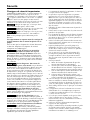
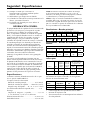
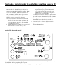
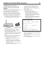
Pump Activity
Activité de pompe
Actividad de la bomba
System Alert
Alerte du système
Alerta del sistema
AC Power
Courant AC
CA
Charging
Recharge
En carga
Battery Status
État de batterie
Estado de la batería
Alarm Silenced
Alarme arrêtée
Alarma apagada
Test System
Tester
Probar sistema
Silence Alarm
Arrêter l’alarme
Apagar alarma
Light
Lumière
Luz
Circuit Breaker
Disjoncteur
Disyuntor
Pump
Pompe
Bomba
Float Switch
Interrupteur à flotteur
Interruptor del flotador
Power
Courant
Encendido
Reset System
Réinitialise
Restrablecer sistema
+
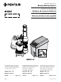
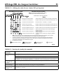
MBSP-3C
Device ID Key
OWNER’S MANUAL
Battery Backup System
NOTICE D’UTILISATION
Système de secours à batterie
MANUAL DEL USUARIO
Sistema de batería de respaldo
Installation/Operation/Parts
For further operating, installation,
or maintenance assistance:
888-987-8677 US
800-387-4386 CA
English ........................... Pages 2-16
Installation/Fonctionnement/Pièces
Pour plus de renseignements
concernant l’utilisation,
l’installation ou l’entretien,
(888) 987-8677 US
(800) 387-4386 CA
Français .................... Pages 17-31
Instalación/Operación/Piezas
Para mayor información sobre el
funcionamiento, instalación o
mantenimiento de la bomba:
888-987-8677 US
800-387-4386 CA
Español ..................... Paginas 32-46

Safety 2
Important Safety Instructions
SAVE THESE INSTRUCTIONS - This manual contains
important instructions that should be followed during
installation, operation, and maintenance of the product.
This is the safety alert symbol. When you see this
symbol on your pump or in this manual, look for one of
the following signal words and be alert to the potential
for personal injury!
indicates a hazard which, if not avoided,
will result in death or serious injury.
indicates a hazard which, if not avoided,
can result in death or serious injury.
indicates a hazard which, if not avoided,
can or may result in minor or moderate injury.
NOTICE addresses practices not related to personal injury.
Carefully read and follow all safety instructions in this
manual and on pumps.
Keep safety labels in good condition. Replace missing or
damaged safety labels.
Battery acid is corrosive. Do not spill on
skin, clothing, or battery charger. Wear eye and head
protection when working with battery. Connect and
disconnect DC output terminals only after removing the
charger from the AC outlet. Never allow the DC
terminals to touch each other.
Hazardous Voltage. Can cause severe or
fatal electrical shock. Do not plug in or unplug battery
charger while standing on a wet floor or in water. Be sure
one hand is free when plugging in or unplugging charger.
If basement floor is wet, disconnect power to basement
before walking on floor. If shut-off box is in basement,
call electric company or hydro authority to shut-off
service to house, or call your local fire department for
instructions. Remove pump and repair or re place. Failure
to follow this warning can result in fatal electrical shock.
Risk of flooding. Do not run pump dry. To
do so will damage seals and can cause leaking and
property damage.
Risk of electrical shock. Do not lift the
pump by the electrical cord; lift pump only by the
discharge pipe, lifting ring or handle on the pump. Lifting
by the cord can damage the cord.
California Proposition 65 Warning
This product and related accessories contain
chemicals known to the State of California to cause
cancer, birth defects or other reproductive harm.
1. Know the pump application, limitations, and potential
hazards.
2. Do not use in water with fish present. If any oil leaks
out of the motor it can kill fish.
NOTICE This unit is not designed as a waterfall or
fountain pump, or for applications involving salt water
or brine! Use with waterfalls, fountains, salt water or
brine will void warranty.
3. Disconnect power before servicing.
4. Drain all water from system before servicing.
5. Secure discharge line before starting pump. An
unsecured discharge line will whip, possibly causing
personal injury and/or property damage.
6. Check hoses for weak or worn condition before each
use, making certain that all connections are secure.
7. Periodically inspect sump, pump and system
components. Keep free of debris and foreign objects.
Perform routine maintenance as required.
8. Provide means of pressure relief for pumps whose
discharge line can be shut-off or obstructed. Release all
pressure within system before servicing any component.
9. Personal Safety:
j. Wear safety glasses at all times when working with
pumps.
k. Keep work area clean, uncluttered and properly
lighted – replace all unused tools and equipment.
l. Keep visitors at a safe distance from work area.
m. Make workshop child-proof – with padlocks, master
switches, and by removing starter keys.
14. Follow local and/or national plumbing and electrical
codes when installing the system. A ground fault
circuit interrupter (GFCI) is recommended for use on
any electrical appliance submerged in water.
15. All wiring should be performed by a qualified
electrician.
16. This equipment is only for use on 115 volt
(single phase) and is equipped with an approved
3-conductor cord and 3-prong, grounding-type plug.
17. Where a 2-prong wall receptacle is encountered, it
must be replaced with properly grounded 3-prong
receptacle installed in accordance with codes and
ordinances that apply.
18. Make certain power source conforms to requirements of
your equipment.
19. Protect electrical cord from sharp objects, hot surfaces,
oil, and chemicals. Avoid kinking cord. Replace or
repair damaged or worn cords immediately.
20. Do not touch an operating motor. Modern motors can
operate at high temperatures.
21. Pump clear water only with this pump.
22. Pump is permanently lubricated at the factory. Do
not try to lubricate it!
23. This pump is designed for use in a residential sump
only.

GENERAL INFORMATION
The Battery Backup Combo Kit is pre-plumbed up to
the hose and clamp assembly. The system includes the
primary sump pump (PSP), backup sump pump (BSP)
assembly, and vertical float switch. The unit is equipped
with two check valves - one for the primary pump and
one for the backup pump.
The battery backup pump is not a substitute for your
primary sump pump. It is designed to temporarily backup
your primary sump pump during a power outage or other
problem which prevents normal operation of the primary
pump. Do not use this system to pump flammable liquids
or chemicals. Pump clear sump water only with this
pump. For residential use only.
Keep the battery charger dry and protected from damage.
This system is designed to work with either a sealed
lead-acid AGM battery or a flooded lead-acid battery.
Use of a true Gel Cell (often confused for AGM) or a
standard automotive battery with this charger is not
recommended. An automotive battery may require
charging after only 1-2 hours of continuous use, and the
repeated charging cycles may cause early plate failure in
the battery.
Specifications
Maximum vertical pumping distance is 15 feet (4.6M) for
Model MBSP-3C.
Power supply required
Primary Sump Pump..........................115V, 60 HZ.
Backup Sump Pump........................12V DC Battery
Liquid Temp. Range..........................32°F to 70°F(0°-21°C)
Individual Branch Circuit Required (min.).............15 Amps
Discharge:
Hose & Clamp Assembly...................1-1/4”Slip / 1-1/2”Slip
Minimum pit diameter ....................................................14”
Minimum depth...............................................................10”
NOTICE Do not reduce size of discharge pipe or hose
below 1-1/4” diameter. If discharge is too small, pump will
overheat and fail prematurely.
NOTICE: If a Carbon Monoxide (CO) sensor is installed,
it must be at least 15 feet away from battery charger
in order to avoid nuisance CO alarms. Please refer
to your CO detector’s installation guidelines for more
information.
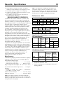
Performance - PSP
GPM (LPM) at total feet (m) of lift
Series HP
5
(1.5m)
10
(3m)
15
(4.6m)
20
(6.1m)
MAX.
LIFTr
Capacity Gallons(L)/Hour
Primary
(MS50V1)
1/2
66
(250)
56
(212)
44
(167)
28
(106)
25 ft
(7.6m)
Performance - BSP
GPM (LPM) at total feet (m) of lift
Series
5
(1.5m)
10
(3m)
14
(4.3m)
MAX.
LIFT
Capacity Gallons(L)/Min
Backup
(PS17-2005)
34
(129)
21
(79)
6
(23)
15
(4.6m)
Electrical & Switch Specifications
Series HP
Motor
Full Load
Amps
Branch
Circuit
Req.
(Amps)
Switch Setting in
inches (cm)
On Off
MS50V1 1/2 4.1
15
7.5
(19.1)
3
(7.6)
PS17-2005 - -
10.5
(26.7)
25 sec.
Required Battery Capacity:
For best results, use the following AGM Storage Batteries:
Part Amp-Hour
Gal/Charge
at 10’
Approx Run
Time
BAT40 40 4,800 5 Hours
BAT75 75 11,500 11.5 Hours
• Unit equipped with dual battery capability
• Maximum amp-hour: 120
• 38-120 Ampere-Hour Storage or Deep Cycle Battery
Safety • Specifications 3

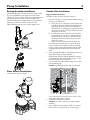
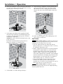
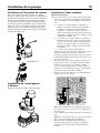
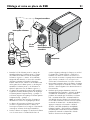
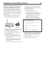
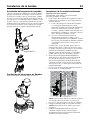
Backup Assembly Installation
Attach backup pump assembly to primary pump. To do
so, un-screw bottom nut on check valve and remove
rubber seal. Place nut from check valve around discharge
PVC pipe on primary pump, then place rubber seal.
Attach backup pump assembly to the primary pump by
tightening nut to the rest of the check valve unit.
Adjust backup pump to sit at an angle (approx. 10°).
Float Switch Installation
Assemble float switch as shown.
Combo Unit Installation
Suggested Materials Needed:
Screwdriver, tape measure, hacksaw, cable ties
1. Drain the sump pit as far as possible without running
the pump dry. Do this by:
A. Piggyback switch: Unplug the pump and switch
from the outlet, then unplug the pump from the
piggyback switch. Reset the circuit breaker or
reinstall the fuse and plug the pump directly into
the outlet. The pump will start. Drain the pit and
unplug the pump. OR
b. No piggyback switch: Reset the circuit breaker
or reinstall the fuse and use a non-conducting
broom handle or stick to raise the float switch;
the pump should start. Drain the pit and then
release the switch.
c. When the pit has drained, turn off (open) the
circuit breaker or remove the fuse again to avoid
electrical shock while working on the installation.
Unplug existing sump pump and place power cord
and piggyback switch out of the way of work and
water.
2. Measure height of MBSP-3C Combo Kit from base to
top of hose clamp assembly. Subtract 1”.
Drop the tape measure into the bottom of sump pit
and mark the cut line on the discharge pipe (1” less
than total height of the Combo Kit).
3. Use hacksaw to cut horizontally along cut line com-
pletely through pipe.
NOTICE Depending on where your current check
valve is located, there may be excess water. Let the
water drain/drip into the sump pit.
4. Remove old sump from sump pit.
NOTICE Remove all sand, clay, and gravel before
installing.
5. Place Combo Kit into sump pit. Make sure vertical
float switches can operate freely inside sump pit.
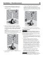
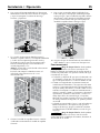
Pump Installation 4
(10° angle)

6. Once the Combo Kit is firmly seated in the base of the
pit, connect the hose and clamp switch to the existing
discharge pipe and clamp it securely.
7. Secure power cord (PSP & BSP), piggyback switch,
and reed switch cord high up and around pipe with
a cable tie. Plug the primary pump into a standard
household 15 amp outlet.
NOTICE The circuit should be dedicated to the sump
pump exclusively.
Remember: Do not handle the pump while it is
plugged in; whether it is running or not.
8. Connect BBU. See “BBU Wiring and Setup”.
9. Once all wiring is complete, fill your pit with water
and verify that the PSP removes the water and the
BBU doesn’t run. Then, unplug your PSP and refill
your pit with water. Verify that the BBU removes the
water.
10. Make sure that the power is on to both pumps, and
your system is ready to use.
Operation
Risk of electric shock. Can shock, burn or kill. Do
not handle a pump or pump motor with wet hands or when
standing on wet or damp surface, or in water.
1. Shaft seal depends on water for lubrication. Do not
operate pump unless it is submerged in water as seal may
be damaged if allowed to run dry.
2. Motor is equipped with automatic reset thermal protector.
If temperature in motor should rise, switch will cut off
all power before damage can be done to motor. When
motor has cooled, switch will reset automatically and
restart motor. If protector trips repeatedly, pump should be
removed and checked. Low voltage, long extension cords,
clogged impeller, very low head or lift, or a plugged or
frozen discharge pipe, etc., could cause cycling.
3. Pump will not remove all water. If operating a pump
manually and suddenly no water comes out of the
discharge hose, shut off the unit immediately. The unit has
broken prime due to a very low water level.
Risk of electric shock. Can shock, burn or kill.
Before attempting to check why unit has stopped operating,
disconnect power from unit.
Installation • Operation 5

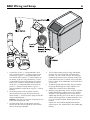
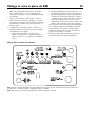
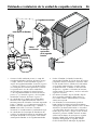
BBU Wiring and Setup 6
1. Connect the positive (+) charger/controller lead
wire (red) to the positive (+) battery terminal (red).
Connect the negative (–) charger/controller lead
wire (black) to the negative (–) terminal (black) on
the battery. If you are using two batteries, use the
set of optional terminals and connect the second
battery. Use lead wires (not included) to connect
the positive (+) charger/controller terminal to the
positive (+) battery terminal and the negative (–)
charger/controller terminal to the negative (–) battery
terminal.
2. The backup pump leads are polarity sensitive;
connect the positive pump lead to the terminal
labeled Pump ‘+’ and the negative pump lead to the
terminal labeled Pump ‘–’.
NOTICE: If the leads are reversed, the pump will run
backward and not pump water.
3. The float switch leads are not polarity sensitive;
connect the float switch leads to the ‘Float Switch’
tabs on the charger/controller.
4. Test the float and the pump by lifting and holding
the float. The system alert LED will blink while
the float is up. The ‘PUMP STATUS’ LED will light
continuously and the buzzer will beep steadily. The
pump should start after 3 seconds. If the pump does
not run, check all the connections and remake them
as necessary.
5. To stop the pump, lower the float; after 25 seconds
the pump should stop, the ‘PUMP STATUS’ LED
should flash, and the buzzer should beep.
6. With the pump operating, test the ‘SILENCE ALARM’
button; hold for one second; release. The ‘ALARM
SILENCED’ LED should illuminate and the buzzer
should stop sounding. To reset the buzzer (allow it to
sound) and extinguish the ‘ALARM SILENCED’ LED,
press the ‘SILENCE ALARM’ button again for one
second.
Depress the ‘TEST SYSTEM’ button; hold it for one
second; release. The ‘PUMP STATUS’ LED should stop
flashing.

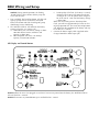
BBU Wiring and Setup 7
NOTICE: When the unit is first plugged in, or when it first receives power from the battery, the ‘BATTERY STATUS’
LED will flash for 3 seconds.
NOTICE: To activate any Control Button, press and hold it for 1 second.
LED Display and Control Buttons
NOTICE: During normal operation, the flashing
‘PUMP STATUS’ LED indicates that the pump has
run in your absence.
1. Press and hold ‘TEST SYSTEM’ button. All LEDs will
light up, pump will run and buzzer will sound.
Release the button and LEDs should go off, pump
should stop, buzzer should stop.
2. The ‘BATTERY STATUS’ LED indicates the battery
capacity when the A.C. power is off.
A. Continuously ON - the battery voltage is above
10.9 Volts Direct Current (10.9VDC) and
capacity is above 20%.
B. Slow Beep/Slow LED Flash - the battery’s
capacity is between 0 and 20%.
C. Fast Beep/Fast LED Flash - the battery is severely
discharged. The battery will continue to charge
(as long as the 115V AC power to the charger is
on) at the rate of .5 AH until the battery’s charge
is above 20%.
When the first warning occurs (slow beep/slow
flash), you will have approximately 2 hours (or less)
of pump operation left. The actual time of operation
will depend on the condition of the battery and may
be as little as 15 minutes.
3. Connect the Power Supply cable (supplied) to the
Charger/Controller’s Power Input jack.

Battery Requirements 8
BATTERY REQUIREMENTS
Hazardous electric current. Can cause
severe burns and start a fire if the battery terminals are
short circuited. Install the battery in the battery case. To
prevent accidental shorting across battery terminals,
close and latch the battery case securely. Do not leave
the battery uncovered.
Do not allow children to play around the battery
backup system installation.
The performance of your backup sump pump depends on
the battery used with it for power. We recommend using
our BAT40 or BAT75. You can also use a group 24M or
27M Deep Cycle battery. They will provide acceptable
performance and will stand up well to long periods of
little or no use.
This system is designed to work with either a sealed
lead-acid AGM battery or a flooded lead-acid battery.
Use of a true Gell Cell (often confused for AGM) or a
standard automotive battery with this charger is not
recommended. An automotive battery may require
charging after only 1-2 hours of continuous use, and the
repeated charging cycles may cause early plate failure in
the battery.
Use only lead-acid batteries. This unit is not designed to
use with Li-Ion, NiMh, NiCAD, Liquid Polymer, etc.
Use only the recommended battery or one of the same
type and size so it will fit in the battery box (maximum
size: 13” long x 7” wide x 10” tall (330.2mm x 177.8mm
x 254mm) including terminals) and supply enough
voltage for full performance.
BATTERY MAINTENANCE
Severe burn hazard. An acid-filled standard
lead-acid battery contains sulfuric acid. Avoid contact with
skin, eyes or clothing.
NOTICE: To protect the battery case from chipping and
gouging, do not let the battery sit on a concrete floor.
Install the battery on a shelf or protective pad (plywood,
2x4s, etc.). Always install the battery in a dry location
that is protected from flooding.
Pre-Qualification Test – 1 and 2
Charger is charging at a very low level to try to bring a
dead battery back to life. If the battery is taking too long,
try resetting the charger once or twice (push the ‘SYSTEM
TEST’ and ‘SILENCE ALARM’ buttons together to reset the
charger).
Special Features:
The charger is equipped with reverse battery, short
circuit, and “runaway charge” protection.
Possible Problems and Remedies
1. Wrong Battery Voltage
Reconnect charger to a 12 volt battery.
2. Reversed Battery Connections
Check all connections. The negative (black) on the
battery must connect to the negative (black) on
the charger, and the positive (red) on the battery
must connect to the positive (red) on the charger.
Reversing the battery connections will cause the
‘SYSTEM ALERT’ and ‘SILENCED AUDIBLE ALARM’
LEDs to flash.
3. Thermal Runaway Condition
“Thermal Runaway” is the technical term for the
condition of the battery when some (or all) of the
cells have deteriorated to the point that they won’t
take a charge. In this case, replace the battery.
4. Charge Time Monitor – 1 and 2
Battery took too long to complete its charge. The
“Charge Time Monitor” will shut down the charger
after 84 hours of continuous charging.
Possible causes are:
A) Pump ran for a long period of time during
charging, or
B) Battery is too large for the charger (including
several batteries connected in a parallel circuit).
Excessive Battery Drain
Pump may have run for a very long time, discharging the
battery. In this case:
a. If 115VAC power is OFF, the charger shuts down
until the power comes back on, but the pump will
run as long as the battery charge lasts. You may need
to replace the battery afterwards.
b. If 115VAC power is ON, the charger/controller
continues to try to charge the battery at a charging
rate of .5 AH until the battery charge is more
than 20%, at which point the charger will resume
charging at a rate of 2 AH.
c. If the pump is running and the AC power is on, you
may need to stop the pump to allow the battery to
charge.
Follow the battery manufacturer’s recommendations for
maintenance and safe use of the battery.

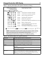
Charger/Controller LED Display 9
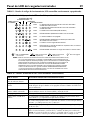
LED Operating Code Display
System Operating Condition
CHARGING
BATTERY STATUS
PUMP ACTIVITY
AC POWER
ALARM SILENCED
SYSTEM ALERT
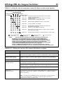
Indicates 115V AC Power is connected / Unit online
NOTICE: All of the situations listed above indicate normal system operation; no action is required.
However, if the BBU pump is running or has run, check the primary pump and actively monitor the
charger status for battery life. Always reset the charger after the pump runs.
During normal system operation, the ‘SYSTEM ALERT’ LED blinks while the float switch is on,
indicating the pump should start within 3 seconds. The “AC POWER” LED is lighted
(solid or blinking) as long as the system is plugged in to an operating AC power circuit.
Indicates Pump is running (continuous LED)
Indicates Audible alarm is switched off
Indicates Battery is charging normally
Indicates Continuous LED: battery charge is above 20%,
system is maintaining charge
Indicates Slow flashing LED: battery charge is below 20%
6790 0313
LED is Flashing (Slow)
=
LED is OFF
LED is ON Continuously
= =
LED is Flashing (Fast)
=
Indicates Fast flashing LED: Pump has run
Indicates Fast flashing LED: Battery pre-qualification test is running
Indicates 115V AC Power is connected / Unit offline
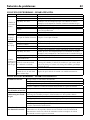
TABLE II – Operating Code Displays (LEDs Lighted Continuously or Flashing)
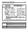
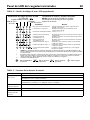
TABLE III – LED Function Displays (LEDs Lighted Continuously)
Control LED: Continuous Illumination Indicates Normal Operation:
AC Power AC power is present. Unit is online.
Pump Status
The float switch has been activated. The LED remains on (flashing) after the pump
has stopped. Depress the ‘SYSTEM TEST’ button to reset it.
Silenced Audible Alarm Audible Alarm has been silenced. Press and release the ‘SILENCE ALARM’ button
to reset (activate) the audible alarm and turn OFF the LED.
Charging
Indicates that the battery is charging – see Table II, above.
Battery Status A. Continuous ON - the battery voltage is above 10.9 Volts DC and capacity is
above 20%.
B. Slow Beep/Slow LED Flash - the battery’s capacity is below 20%, and voltage is
between 8.2VDC and 10.9VDC.
C. Fast Beep/Fast LED Flash - the battery has been discharged to less than 8.2VDC.
System Alert Flashing (in unison with the buzzer) indicates that the charger has entered ‘Failure
Mode’. Press the ‘SYSTEM TEST’ and ‘SILENCE ALARM’ buttons to reset it.
NOTICE: If the source of the failure is not corrected, the charger will reenter
“Failure Mode”. See Table IV for error code information.

Charger/Controller LED Display 10
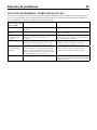
TABLE IV – Error Code Displays (LEDs Flashing)
TABLE V – Control Button Functions
Control Button: Result of Pushing Button:
System Test Pump starts and all LEDs light up.
Will reset the ‘PUMP ACTIVITY’ LED.
When pushed with the ‘SILENCE ALARM’ button, the Charger/Controller microprocessor resets
and error code resets.
Silence Alarm Toggle; Prevents the audible alarm sounding. Press and release to reset.
Light Toggles the light on the Charger/Controller on and off.
System Reset Press and release ‘TEST SYSTEM’ and ‘SILENCE ALARM’ to reset system.

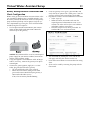
Battery Backup Internet Connection and
Alerts Configuration
Before setting up the Virtual Water Assistant (VWA), make
sure your Battery Backup Unit is installed correctly, refer
to Owner’s Manual for instruction. Make sure the primary
pump and battery backup unit has power. Verify the sys-
tem is operational by pressing the ‘TEST SYSTEM’ button
and observing the test sequence.
1. Find an open network connection on your internet
router or other hard-wired connection. Rotate the
antennae up on the gateway.
NOTICE: We recommend the use of an uninterrupted
power supply for your internet modem, home router
and the gateway power supply.
2. Using the supplied 1 meter Ethernet cable (or longer
cable if necessary), connect the gateway to an open
network port.
3. Connect the gateway power supply to a 115 VAC
outlet, plug into the back of the gateway.
• The LED will blink red for a few seconds.
• When the LED becomes solid green or solid
green with an occasional blink your gateway is
connected to the VWA servers.
If not, refer to Gateway Troubleshooting.
4. Once the gateway LED is green, go to the BBU and
verify that the AC power LED is solid green. If not, the
gateway will have to be moved closer to the BBU.
5. Log onto the website www.VirtualWaterAssistant.com
• Select “Sign Up”
• Follow the online instructions and enter the
required personal information to create a user
account. The Alerts will use the e-mail addresses
and phone numbers entered here.
• Enter the Unique Device ID Key included - lo-
cated on BBU case and manual cover.
6. Test installation by clicking the “Test” icon on the
web page and verify the unit has run the test.
7. Refer to the Virtual Water Assistant website for setting
alerts.
8. Alerts can be tested by activating the pump with the
float switch.
Virtual Water Assistant Setup 11

Pump won’t run: Check all the wiring connections.
Check for a low or defective battery.
Check that the automatic switch is free to move up and down.
Press the circuit breaker reset button on the control panel.
Motor hums but pump won’t run: Check for low or defective battery.
Pump runs but pumps very little or no water: Make sure a check valve is installed and functioning between the
primary pump discharge and the Battery Backup wye.
Check for an obstruction in the discharge pipe.
The discharge pipe length and/or height exceeds the capacity of the
pump.
Check for a low or defective battery.
The Positive (+) and negative (–) pump wires are reversed.
Disconnect them and reconnect correctly.
Pump cycles too frequently: The check valve located between the discharge of the primary
pump and the Battery Backup wye is not installed or is not
working properly. Install an auxiliary check valve or replace the
existing check valve as required.
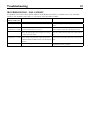
TROUBLESHOOTING - PRIMARY PUMP
Troubleshooting 12
Symptom Possible Cause(s) Corrective Action
Pump won’t
start or run.
Pump is not plugged in. Check and see if pump is plugged into a proper outlet.
Blown fuse. If blown, replace with fuse of proper size.
Low line voltage
If voltage under recommended minimum, check size of wiring from main
switch on property. If OK, contact power company or hydro authority.
Defective motor. Replace pump.
Defective float switch. Replace float switch.
Impeller
If impeller won’t turn, remove lower pump body and locate source of
binding.
Float obstructed Remove obstruction.
Pump starts
and stops too
often.
Backflow of water from piping Install or replace check-valve.
Faulty float switch Replace float switch.
Pump won’t
shut off
Defective float switch Replace float switch.
Restricted discharge (obstacle or ice in
piping)
Remove pump and clean pump and piping.
Float obstructed Remove obstruction.
Restricted intake screen Remove the pump and clean the intake screen and the impeller.
Pump
operates but
delivers little
or no water
Low line voltage
If voltage under recommended minimum, check size of wiring from main
switch on property. If OK, contact power company or hydro authority.
Something caught in impeller Remove the pump and clean out the impeller.
Worn or defective parts or plugged
impeller
Clean impeller if plugged; otherwise replace pump.
Check valve installed without vent
hole.
Drill a 1/16” - 1/8” (1.6mm-3.2mm) dia. hole between pump discharge &
check valve (1-2” above where the discharge pipe screws into the pump
discharge and below the waterline).
Restricted intake screen Remove the pump and clean out the intake screen.
Check valve is installed either
backward or upside down
Be sure check valve is installed correctly.
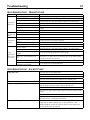
TROUBLESHOOTING - BACKUP PUMP

IF GATEWAY LED LIGHT IS NOT GREEN (GREEN, SLOW BLINK) FIRST TRY TO “POWER CYCLE” THE GATEWAY
(UNPLUG THE POWER CORD, WAIT 15+ SECONDS, THEN RE-APPLY POWER).
Gateway Status
Indicator (LED Color)
Definition Action Needed
Green Power on: gateway connected to servers. OK - Connection complete and operational
Green, quick blink Power on: data traffic to servers. OK - Operating, data is moving between BBU and
Server
Green, slow blink
(1-2 blinks per second)
Power on: gateway connected to local router, but
not connected to Internet or servers.
System is online and scanning for destination/server
(add a network switch inline to help define unit).
Red Power on: gateway has no local connection to
router. The gateway does not "recognize/see" that it
is connected to the router.
Check Ethernet cable connections and/or quality or
cable. Try a different router port. Is the router turned
on.
Red, slow blink
(1-2 blinks per second)
Power on: gateway communicating with router, but
router cannot assign Dynamic Host Configuration
Protocol (DHCP) or Domain Name System (DNS) to
gateway.
Router is not permitting the gateway to access the
internet (add a network switch inline to help define
unit).
Off Power off or product fault. Check power source, verify power adapter is
functioning. Defective gateway.
Troubleshooting 13
TROUBLESHOOTING - VWA GATEWAY

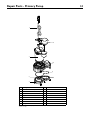
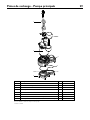
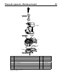
Repair Parts - Primary Pump 14
1
2
3
4
5
6
7
*If motor fails, replace entire pump.
•Purchaselocally|
Ref Description Qty
MS50V1
1 Power Cord Assembly 1 PS117-54-TSU
2 Vertical Float Switch Assembly 1 FPS17-66
3 Motor 1 *
4 Upper Volute 1 PS1-324
5 Impeller 1 PS5-286
6 Lower Volute 1 PS1-326
7 Screw #8-32 x 1/2” 10 •
8 O-ring -162 Buna-N 5.75” x 3/32” 1 U9-470
8

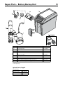
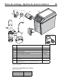
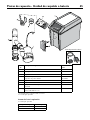
Repair Parts - Battery Backup Unit 15
Key No. Part Description Part Number
1 DC Backup Pump PS17-2005*
2 Float Switch PS17-2003
3 Charger/Controller PS217-1522
4 Battery Case Base
Battery Case Cover
PS17-2044
PS17-2045
5 AC Adaptor PS17-2008
6 Cable Ties - 11” **
7 Backup Combo Plumbing Kit (with check valves) U137-692
8 Gateway Kit: Gateway, Power Supply, 1m RJ45 Cable U117-1568
* If pump fails, replace entire system.
** Sold separately.
Part Description Part Number
AGM 75A-Hour BAT75
AGM 40A-Hour BAT40
Optional Battery Supplies
Sold Separately

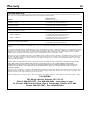
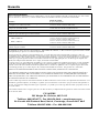
Warranty 16
Limited Warranty
Myers
®
warrants to the original consumer purchaser (“Purchaser” or “You”) of the products listed below, that they will be free
from defects in material and workmanship for the Warranty Period shown below.
Product
Warranty Period
whichever occurs first:
Jet pumps, small centrifugal pumps, submersible pumps and
relatedaccessories
12 months from date of original installation,
or 18 months from date of manufacture
Fibrew
ound Tanks 5 years from date of original installation
Steel Pressure Tanks 5 years from date of original installation
Sump/Sewage/Effluent Products
12 months from date of original installation,
or 36 months from date of manufacture
Battery Backup Units
MBSP-2, MBSP-2C
MBSP-3, MBSP-3C
12 months from date of original installation,
or 18 months from date of manufacture
24 months from date of original installation,
or 30 months from date of manufacture
Wastew
ater Solids Handling Pumps
12 months from date of shipment from factory
or 18 months from date of manufacture
Our warranty applies only where such products are used in compliance with the requirements of the applicable product catalog
and/or manuals. For additional information, please refer to the applicable standard limited warranty featured in the product
manual.
Our warranty will not apply to any product that, in our sole judgement, has been subject to negligence, misapplication, improper
installation, or improper maintenance. Without limiting the foregoing, operating a three phase motor with single phase power
through a phase converter will void the warranty. Note also that three phase motors must be protected by three-leg, ambient
compensated, extra-quick trip overload relays of the recommended size or the warranty is void.
Your only remedy, and MYERS’s only duty, is that MYERS repair or replace defective products (at MYERS’s choice). You must pay
all labor and shipping charges associated with this warranty and must request warranty service through the installing dealer as
soon as a problem is discovered. No request for service will be accepted if received after the Warranty Period has expired. This
warranty is not transferable.
MYERS SHALL NOT BE LIABLE FOR ANY CONSEQUENTIAL, INCIDENTAL, OR CONTINGENT DAMAGES WHATSOEVER.
THE FOREGOING LIMITED WARRANTIES ARE EXCLUSIVE AND IN LIEU OF ALL OTHER EXPRESS AND IMPLIED
WARRANTIES, INCLUDING BUT NOT LIMITED TO IMPLIED WARRANTIES OF MERCHANTABILITY AND FITNESS FOR
A PARTICULAR PURPOSE. THE FOREGOING LIMITED WARRANTIES SHALL NOT EXTEND BEYOND THE DURATION
PROVIDED HEREIN.
Some states do not allow the exclusion or limitation of incidental or consequential damages or limitations on the duration of an
implied warranty, so the above limitations or exclusions may not apply to You. This warranty gives You specific legal rights and
You may also have other rights which vary from state to state.
This Limited Warranty is effective April 1, 2014 and replaces all undated warranties and warranties dated before April 1, 2014.
F.E. MYERS
293 Wright Street, Delavan, WI 53115
Phone: 888-987-8677 • Fax: 800-426-9446 • www.femyers.com
In Canada: 490 Pinebush Road, Unit 4, Cambridge, Ontario N1T 0A5
Phone: 800-363-7867 • Fax: 888-606-5484

Sécurité 17
Consignes de sécurité importantes
CONSERVER CES DIRECTIVES - Ce manuel contient des
directives importantes devant être respectées lors de
l'installation, de l'utilisation et de l'entretien de ce produit.
Il s'agit du symbole d'alerte à la sécurité. Ce symbole,
lorsqu'il se trouve sur votre pompe ou votre manuel,
signale qu'il faut chercher la présence de l'un de ces mots
indicateurs et être conscient des risques de blessure!
indique un risque qui, s'il n'est pas évité,
causera des blessures graves, voire la mort.
indique un risque qui, s'il n'est pas évité,
peut causer des blessures graves, voire la mort.
indique un risque qui, s'il n'est pas évité,
peut causer des blessures mineures, voire modérées.
AVIS vise des pratiques qui ne concernent pas les
blessures.
Lire soigneusement et respecter toutes les consignes de
sécurité contenues dans ce manuel ou placées sur les
pompes.
Faire en sorte que les étiquettes de sécurité demeurent
en bon état. Remplacer les étiquettes de sécurité
manquantes ou endommagées.
L'acide de batterie est une matière
corrosive. Ne pas mettre en contact avec la peau,
les vêtements ou le chargeur de batterie. Porter une
protection oculaire et à la tête lorsqu'il est nécessaire
de manipuler des batteries. Brancher et débrancher les
bornes de sortie CC uniquement après avoir débranché
le chargeur de la prise CA. Ne jamais laisser les bornes
CC se toucher.
Tension dangereuse. Peut causer des
chocs électriques graves, voire mortels. Ne pas brancher
ou débrancher le chargeur de batterie lorsque vous vous
tenez sur une surface mouillée ou inondée. S'assurer
qu'une main demeure libre au moment de brancher ou
de débrancher le chargeur. Si le plancher du sous-sol est
mouillé, couper l'alimentation électrique vers le sous-sol
avant de marcher sur le plancher. Si la boîte d'arrêt est au
sous-sol, communiquer avec la compagnie d'électricité
ou le service d'hydro pour obtenir une interruption de
service vers la maison; il est aussi possible d'appeler le
service local de lutte contre les incendies pour obtenir
des directives. Retirer la pompe et la faire réparer ou
la remplacer. Tout manquement à tenir compte de cet
avertissement peut entraîner un choc électrique mortel.
Risque d'inondation. Ne pas faire
fonctionner la pompe à sec. Ce faisait, les joints de la
pompe seront endommagés, créant potentiellement une
fuite et des dommages à la propriété.
Risque de choc électrique. Ne pas
soulever la pompe par son cordon électrique; plutôt, la
soulever par le tuyau de décharge, l'anneau de levage ou
la poignée qui se trouve dessus. Le cordon pourrait être
endommagé s'il est utilisé pour soulever la pompe.
Avertissement relatif à la Proposition 65 en California
Ce produit, de même que les
accessoires qui y sont associés, contient des produits
chimiques considérés cancérigènes ou pouvant causer
des déficiences de naissance ou autres problèmes
reproductifs par l'état de la California.
1. Il est important de connaître les applications, les limites et
les risques inhérents de la pompe.
2. Ne pas utiliser en présence de poissons. Les poissons
pourraient être tués en cas de fuite d'huile du moteur.
AVIS Cette unité n'a pas été conçue pour être utilisée en
tant que pompe pour chute d'eau ou fontaine ni pour les
applications impliquant de l'eau salée ou de la saumure!
La garantie de la pompe sera annulée si elle est utilisée
avec des chutes d'eaux, des fontaines ou en eau salée ou
dans la saumure.
3. Débrancher la source d'alimentation avant de procéder à
des réparations.
4. Drainer toute l'eau qui se trouve dans le système avant de
procéder à des réparations.
5. Fixer la conduite de décharge avant de démarrer la pompe.
Une conduite de décharge qui n'est pas bien fixée peut
agir comme un fouet, ce qui est une source potentielle de
blessures ou de dommages.
6. Vérifier les flexibles pour détecter tout bris ou toute trace
d'usure avant chaque utilisation, tout en s'assurant que les
raccords sont bien en place.
7. Inspecter périodiquement le puisard, la pompe et les
composantes du système. S'assurer qu'il demeure libre
de tous débris et corps étrangers. Exécuter une procédure
d'entretien de routine au besoin.
8. Faire en sorte qu'il y ait un système d'évacuation de la
pression pour les pompes dont la conduite de décharge
est coupée ou obstruée. Libérer la pression accumulée
dans le système avant de procéder à tout service sur une
composante.
9. Sécurité personnelle:
a. Porter des lunettes de protection dès que des
travaux sont effectués sur des pompes.
b. Assurer que la zone de travail est propre, libre
de tout obstacle et bien éclairée - ranger tous les
outils et les équipements qui ne sont pas utilisés.
c. Faire en sorte que les visiteurs demeurent à une
distance sécuritaire de la zone de travail.
d. Créer un atelier à l'épreuve des enfants - par
l'ajout de cadenas, de commutateurs principaux
et par le retrait des clés du démarreur.
10. Suivre les consignes des codes de plomberie et d'électricité
locaux et nationaux au moment d'installer le système. Il
est recommandé d'utiliser un disjoncteur de fuite de terre
(GFCI) avec tout appareil électrique submergé dans l'eau.
11. Tout le câblage devrait être mis en place par un électricien
compétent.
12. Cet équipement est destiné à utilisation avec une source
d'alimentation de 115V (monophasique) uniquement;
ilest doté d'un cordon conducteur à 3 fils et d'une prise
à3 fiches avec mise à la terre.
13. Si la seule prise murale disponible est de type à 2 fiches,
il faut la remplacer par une prise de type à 3 fiches
correctement mise à la terre, conformément aux codes et
ordonnances applicables.
14. Vérifier que la source d'alimentation correspond aux
exigences de votre équipement.
15. Protéger le cordon électrique de tout objet tranchant; le garder
à l'égard des surfaces chaudes, de l'huile et des produits
chimiques. Éviter de tordre le cordon. Remplacer ou réparer
immédiatement un cordon s'il est endommagé ou usé.

16. Ne pas toucher à un moteur en marche. Les moteurs
modernes peuvent fonctionner à des températures élevées.
17. Ne pomper que de l'eau propre avec cette pompe.
18. La pompe a été lubrifiée de manière permanente en usine.
Ne pas essayer de la lubrifier!
19. Cette pompe a été conçue pour être utilisée dans un
puisard résidentiel uniquement.
RENSEIGNEMENTS GÉNÉRAUX
La plomberie de la trousse combinée de secours à bat-
terie est mise en place en usine, jusqu'à l'ensemble de
flexible et de collier. Le système comprend la pompe de
puisard principale (PPP), l'ensemble de pompe de puisard
de secours (PPS) et l'interrupteur à flotteur vertical.
L'unité est dotée de deux clapets de non retour; un pour
la pompe principale, l'autre pour la pompe de secours.
La pompe de puisard à batterie de secours ne peut
pas se substituer à votre pompe principale. Elle a été
conçue pour agir en tant que support pour votre pompe
principale en cas de panne d'électricité ou de tout
autre problème nuisant au fonctionnement normal de la
pompe primaire. Ne pas utiliser ce système pour pomper
des liquides inflammables ou des produits chimiques.
Ne se servir de cette pompe que pour pomper de l'eau
propre. Pour utilisation résidentielle uniquement.
Assurer que le chargeur de batterie demeure au sec et
bien protégé contre tout dommage.
Ce système a été conçu pour fonctionner avec une batterie
AGM (plomb-gel et feutre) scellée ou une batterie plomb-
acide à électrolyte liquide. L'utilisation d'une vraie batterie
à électrolyte gélifié (souvent confondue pour une batterie
AGM) ou d'une batterie automobile standard n'est pas
recommandée avec ce chargeur. Il pourrait être nécessaire
de laisser recharger une batterie automobile après
seulement 1 ou 2 heures d'utilisation continue ; les
cycles de chargement répétés pourraient ruiner
complètement les plaques de la batterie.
Spécifications
La distance de pompage verticale maximale de la pompe
est de 4,6m (15pi), dans le cas du modèle MBSP-3C.
Alimentation électrique requise
Pompe de puisard principale......................115V, 60 HZ.
Pompe de puisard de secours.................Batterie 12VCC
Plage de température des liquides.....0° à 21°C (32° à 70°F)
Circuit de division individuel requis (min.)..........15ampères
Décharge:
Ensemble de flexible et de collier..........Manchon de
3,17/3,80cm (1-1/4po/1-1/2po)
Diamètre minimum du puits ......................35,56cm (14po)
Profondeur minimum..................................25,40cm (10po)
AVIS Ne pas réduire la taille du tuyau ou du flexible de
décharge à un diamètre inférieur à 3,17cm (1-1/4po). Si la
décharge est trop étroite, cela peut entraîner la surchauffe et
l'arrêt prématurés de la pompe.
AVIS: si un détecteur de monoxyde de carbone (CO)
est installé, il doit se trouver à au moins 4,6m (15pi)
du chargeur de batterie, ce afin d'éviter l'occurrence de
fausses alarmes. Se reporter aux directives d'installation
du détecteur de CO pour en apprendre davantage.
Performance - PPP
L/m (Gal/m) à un soulèvement total de xx m (pi)
Série HP
1,5 m
(5)
3 m
(10)
4,6 m
(15)
6,1 m
(20)
SOULÈVE-
MENT
MAX
Capacité en L/m (Gal/m)
Principale
(MS50V1)
1/2
250
(66)
212
(56)
167
(44)
106
(28
7,6m
(25pi)
Performance - PPS
L/m (Gal/m) à un soulèvement total de xx m (pi)
Série
0
(0)
1,5
(5)
3
(10)
SOULÈVEMENT
MAX
Capacité en L/m (Gal/m)
Secours
(PS17-2005)
170
(45)
129
(34)
80
(21)
4,6
(15)
Spécifications électriques et spécifications
de l'interrupteur
Série HP
Puissance
à pleine
charge
du mo-
teur
Exigence
pour le
circuit de
division
(ampères)
Réglage de
l'interrupteur, en cm
(po)
Position
marche
Position
arrêt
MS50V1 1/2 4,1
15
19,1
(7,5)
7,6
(3)
PS17-2005 - -
26,7
(10,5)
25 sec.
Capacité de batterie requise:
Pour obtenir de meilleurs résultats, se servir des batteries
à stockage AGM suivantes:
Pièce Amp-Heure
Gal/Charge
à 3m
(10pi)
Temps
de fonc-
tionnement
approx
BAT40 40 4 800 5heures
BAT75 75 11 500 11,5heures
• Unité pouvant être équipée d'une batterie double
• Amp-heure maximum: 120
• Batterie à stockage de 38-120ampères-heures ou à
décharge poussée
Sécurité • Spécifications 18

Installation de l'ensemble de secours
Relier l'ensemble de pompe de secours à la pompe
principale. Pour ce faire, il faut dévisser l'écrou inférieur
du clapet de non retour et retirer le joint de caoutchouc.
Placer ensuite l'écrou du clapet de non retour autour
du tuyau de PVC de décharge de la pompe principale
et remettre le joint de caoutchouc. Fixer l'ensemble de
pompe de secours à la pompe principale en resserrant
l'écrou sur le reste de l'unité de clapet de non retour.
Ajuster la pompe de secours pour qu'elle soit installée à
un angle (d'environ 10°).
Installation de l'interrupteur
à flotteur
Monter l'interrupteur à flotteur comme montré.
Installation de l'unité combinée
Matériaux requis suggérés:
Tournevis, ruban à mesurer, scie à métaux, attaches pour câble
1. Vider le puits de puisard aussi profondément que possible
sans que la pompe se mette à fonctionner à vide. Pour ce
faire:
a. iNterrupteur de sortie coNjoiNte: débrancher la
pompe et l'interrupteur de la prise puis débrancher
la pompe de l'interrupteur de sortie conjointe.
Réinitialiser le disjoncteur de circuit ou remettre le
fusible en place puis brancher la pompe directement
dans la prise. La pompe va démarrer. Vidanger le puits
et débrancher la pompe. OU
b. saNs iNterrupteur de sortie coNjoiNte: réinitialiser le
disjoncteur de circuit ou remettre le fusible en place
et se servir d'un manche à balai ou d'un bâton pour
soulever l'interrupteur à flotteur, ce qui devrait faire
fonctionner la pompe. Vidanger le puits puis relâcher
l'interrupteur.
C. Une fois le puits vidangé, couper (ouvrir) le
disjoncteur de circuit ou enlever le fusible à nouveau pour
éviter tout choc électrique pendant l'installation.
Débrancher la pompe de puisard déjà en place et mettre le
cordon d'alimentation et l'interrupteur à l'écart de l'eau et
de l'espace de travail.
2. Mesurer la hauteur de la trousse combinée MBSP-3C, de
la base jusqu'en haut de l'ensemble de flexible et collier.
Soustraire 2,54 cm (1 po). Laisser tomber le ruban à
mesurer jusqu'au fond du puisard et marquer la ligne de
coupe sur le tuyau de décharge 2,54cm - (1 po) de moins
que la hauteur totale de la trousse combinée.
3. Utiliser la scie à métaux pour faire une coupe horizontale
complète du tuyau, à la marque.
AVIS Selon la position actuelle du clapet de non retour, il
peut y avoir un excès d'eau. Laisser l'eau s'écouler dans le
trou du puisard.
4. Retirer la pompe de puisard qui était déjà en place dans le
puits.
AVIS Retirer tout le sable, l'argile et le gravier qui se trouver
dans le puits avant de procéder à l'installation.
5. Mettre la trousse de combinaison dans le puits
de puisard. Vérifier que les interrupteurs à flotteur
verticaux peuvent être actionnés librement dans le
puisard.
Installation de la pompe 19
(angle de 10°)

6. Une fois la trousse combinée bien placée au fond
du puisard, brancher le flexible et le collier de
l’interrupteur au tuyau de décharge déjà en place
etbien fixer le tout.
7. Bien fixer le cordon d’alimentation (de la PPP et
de la PPS), l’interrupteur enroulé et le cordon de
l’interrupteur à lames en hauteur et autour du tuyau
à l’aide d’une attache de câble. Brancher la pompe
principale dans une prise domestique normale de
15ampères.
AVIS Le circuit utilisé devrait être exclusivement dédié
au fonctionnement de la pompe de puisard.
Rappel: ne pas manipuler la pompe pendant qu’elle
est branchée, qu’elle fonctionne ou non.
8. Brancher le SSB. Se reporter à «Câblage et mise en
place du SSB».
9. Une fois le câblage en place, remplir le puits d'eau
et vérifier que la pompe de puisard principale
fonctionne mais que le SSB ne démarre pas. Ensuite,
débrancher la pompe de puisard principale et remplir
le puits d'eau à nouveau. Vérifier que le SSB parvient
à éliminer l'eau.
10. S'assurer que les deux pompes sont alimentées en
électricité; votre système est maintenant prêt à utiliser.
Fonctionnement
Risque de choc électrique. Possibilité de
choc, de brûlure et même de décès. Ne pas manipuler une
pompe ou le moteur de la pompe pendant que vous avez
les mains humides ou que vous vous tenez sur une surface
humide ou mouillée ou dans l'eau.
1. Le joint de l'arbre du moteur est lubrifié par l'eau. Ne pas
faire fonctionner la pompe lorsqu'elle ne se trouve pas
dans l'eau; cela pourrait endommager le joint si la pompe
fonctionne à sec.
2. Le moteur est doté d'un protecteur thermique à
réinitialisation automatique. En cas de hausse de la
température du moteur, l'interrupteur interrompra
toute arrivée de puissance avant que le moteur ne soit
endommagé. Une fois le moteur refroidi, l'interrupteur
est automatiquement réinitialisé et le moteur redémarre.
Si le dispositif de protection se déclenche à répétition,
ilfaut mettre la pompe hors service et la faire vérifier.
Lescycles de déclenchement peuvent être causés par une
faible tension, des rallonges trop longues, un agitateur
obstrué, une tête ou un soulèvement trop bas, un tuyau
de décharge bouché ou gelé, etc.
3. La pompe ne permettra pas de retirer toute l'eau.
Si la pompe est actionnée manuellement, il faut
immédiatement arrêter l'unité lorsque l'eau cesse de
sortir du flexible de décharge. L'unité a une amorce
briséeà cause d'un niveau d'eau très bas.
Risque de choc électrique. Possibilité de
choc, de brûlure et même de décès. Débrancher l'unité avant
de tenter de découvrir pourquoi elle ne fonctionne plus.
Installation • Fonctionnement 20
La page charge ...
La page charge ...
La page charge ...
La page charge ...
La page charge ...
La page charge ...
La page charge ...
La page charge ...
La page charge ...
La page charge ...
La page charge ...
La page charge ...
La page charge ...
La page charge ...
La page charge ...
La page charge ...
La page charge ...
La page charge ...
La page charge ...
La page charge ...
La page charge ...
La page charge ...
La page charge ...
La page charge ...
La page charge ...
La page charge ...
La page charge ...
La page charge ...
-
 1
1
-
 2
2
-
 3
3
-
 4
4
-
 5
5
-
 6
6
-
 7
7
-
 8
8
-
 9
9
-
 10
10
-
 11
11
-
 12
12
-
 13
13
-
 14
14
-
 15
15
-
 16
16
-
 17
17
-
 18
18
-
 19
19
-
 20
20
-
 21
21
-
 22
22
-
 23
23
-
 24
24
-
 25
25
-
 26
26
-
 27
27
-
 28
28
-
 29
29
-
 30
30
-
 31
31
-
 32
32
-
 33
33
-
 34
34
-
 35
35
-
 36
36
-
 37
37
-
 38
38
-
 39
39
-
 40
40
-
 41
41
-
 42
42
-
 43
43
-
 44
44
-
 45
45
-
 46
46
-
 47
47
-
 48
48


dans d''autres langues
- English: MYERS MBSP-3C Owner's manual
- español: MYERS MBSP-3C El manual del propietario
Documents connexes
-
MYERS MBSP-3 Le manuel du propriétaire
-
-
-
-
-
Pentair MYERS MSC133 Le manuel du propriétaire
-
-
-
-
Autres documents
-
Hydromatic FG-3100RC Battery Backup Systems Le manuel du propriétaire
-
Flotec FPCC5030 Le manuel du propriétaire
-
-
-
-
-
-
 Utilitech KLH075 Manuel utilisateur
-
Wayne 56835-002 Mode d'emploi
