NOMA Hayden 3-Reversible Blade 6-Speed Le manuel du propriétaire
- Catégorie
- Ventilateurs ménagers
- Taper
- Le manuel du propriétaire

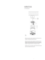
HAYDEN
44" LED CEILING FAN
PRODUCT NO. 052-9716-0
USER MANUAL
READ AND SAVE THESE INSTRUCTIONS

2 3
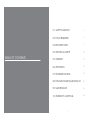
TABLE OF CONTENTS
01. SAFETY/CAUTIONS
02. TOOLS REQUIRED
03. EXPLODED VIEW
04. ELECTRICAL SAFETY
05. ASSEMBLY
06. OPERATION
07. TROUBLESHOOTING
08. DYNAMIC BLADE BALANCING KIT
09. MAINTENANCE
10. WARRANTY & DISPOSAL
4
6
7
10
12
19
20
22
24
25

2
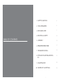
TABLE OF CONTENTS
1. SAFETY/CAUTIONS
2. TOOLS REQUIRED
3. EXPLODED VIEW
4. ELECTRICAL SAFETY
5. ASSEMBLY
6. REMOTE INSTRUCTION
7. TROUBLESHOOTING
8. DYNAMIC BLADE BALANCING
KIT
9. MAINTENANCE
10. WARRANTY & DISPOSAL
4
6
7
10
12
17
19
21
23
24
3

5
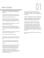
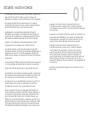
01
SAFETY / CAUTIONS
•
•
•
•
•
•
•
•
•
•
TO REDUCE THE RISK OF ELECTRIC SHOCK, ENSURE ELECTRICITY HAS
BEEN TURNED OFF AT THE CIRCUIT BREAKER OR FUSE BOX BEFORE
BEGINNING.
ALL WIRING MUST BE IN ACCORDANCE WITH THE NATIONAL AND
LOCAL ELECTRICAL CODES. ELECTRICAL INSTALLATION SHOULD BE
PERFORMED BY A QUALIFIED LICENSED ELECTRICIAN.
WARNING: TO REDUCE THE RISK OF ELECTRIC SHOCK OR FIRE, DO
NOT USE THIS FAN WITH ANY SOLID-STATE FAN-SPEED CONTROL
DEVICE. IT WILL PERMANENTLY DAMAGE THE ELECTRONIC CIRCUITRY.
CAUTION: TO REDUCE THE RISK OF PERSONAL INJURY, USE ONLY THE
SCREWS PROVIDED WITH THE OUTLET BOX.
THE OUTLET BOX AND SUPPORT STRUCTURE MUST BE SECURELY
MOUNTED AND CAPABLE OF RELIABLY SUPPORTING A MINIMUM OF
50 LB (22.7 KG). USE ONLY UL-LISTED OUTLET BOXES MARKED "FOR FAN
SUPPORT."
THE FAN MUST BE MOUNTED WITH A MINIMUM OF 10’ (3.05 M) FROM
THE TRAILING EDGE OF THE BLADES TO THE FLOOR.
AVOID PLACING OBJECTS IN THE PATH OF THE BLADES.
TO AVOID PERSONAL INJURY OR DAMAGE TO THE FAN AND OTHER
ITEMS, BE CAUTIOUS WHEN WORKING AROUND OR CLEANING THE
FAN.
DO NOT USE WATER OR DETERGENTS WHEN CLEANING THE FAN
OR FAN BLADES. A DRY DUST CLOTH WILL BE SUITABLE FOR MOST
CLEANING.
AFTER MAKING ELECTRICAL CONNECTIONS, SPLICED CONDUCTORS
SHOULD BE TURNED UPWARD AND PUSHED CAREFULLY UP INTO
THE OUTLET BOX. THE WIRES SHOULD BE SPREAD APART WITH THE
GROUNDED CONDUCTOR AND THE EQUIPMENT-GROUNDING
CONDUCTOR ON ONE SIDE OF THE OUTLET BOX AND THE
UNGROUNDED CONDUCTOR ON THE OTHER SIDE OF THE OUTLET BOX.
ALL SET SCREWS MUST BE CHECKED AND RE-TIGHTENED WHERE
NECESSARY BEFORE INSTALLATION.
•
•
•
•
WARNING: TO REDUCE THE RISK OF FIRE, ELECTRIC SHOCK
AND PERSONAL INJURY, MOUNT FAN TO OUTLET BOX MARKED
“ACCEPTABLE FOR FAN SUPPORT” WITH THE SCREWS PROVIDED WITH
THE OUTLET BOX
WARNING: TO AVOID RISK OF PERSONAL INJURY, DO NOT BEND THE
BLADE ARMS (ALSO REFERRED TO AS FLANGES) OR THE BRACKETS
WHILE BALANCING THE BLADES OR CLEANING THE FAN. DO NOT
INSERT FOREIGN OBJECTS BETWEEN ROTATING FAN BLADES.
WARNING: TO REDUCE THE RISK OF FIRE, ELECTRIC SHOCK
AND PERSONAL INJURY, MOUNT FAN TO OUTLET BOX MARKED
“ACCEPTABLE FOR FAN SUPPORT” OF 35LB (15.9 KG) OR LESS”
AND USE MOUNTING SCREWS PROVIDED WITH THE OUTLET BOX.
MOST OUTLET BOXES COMMONLY USED FOR THE SUPPORT OF
LIGHT FIXTURES ARE NOT ACCEPTABLE FOR FAN SUPPORT AND MAY
NEED TO BE REPLACED. DUE TO THE COMPLEXITY OF THIS FAN, A
QUALIFIED LICENSED ELECTRICIAN IS STRONGLY RECOMMENDED FOR
INSTALLATION.
ATTENTION: PLEASE ENSURE LED BULBS TOTAL WATTAGE IS ALWAYS
BELOW 70 W!
4

4
SAFETY / CAUTIONS
SAFETY CONCERNS
•
•
•
•
•
•
•
•
•
•
TO REDUCE THE RISK OF ELECTRIC SHOCK, ENSURE ELECTRICITY HAS
BEEN TURNED OFF AT THE CIRCUIT BREAKER OR FUSE BOX BEFORE
BEGINNING.
ALL WIRING MUST BE IN ACCORDANCE WITH THE NATIONAL AND
LOCAL ELECTRICAL CODES. ELECTRICAL INSTALLATION SHOULD BE
PERFORMED BY A QUALIFIED LICENSED ELECTRICIAN.
WARNING: TO REDUCE THE RISK OF ELECTRIC SHOCK OR FIRE, DO
NOT USE THIS FAN WITH ANY SOLID-STATE FAN-SPEED CONTROL
DEVICE. IT WILL PERMANENTLY DAMAGE THE ELECTRONIC CIRCUITRY.
CAUTION: TO REDUCE THE RISK OF PERSONAL INJURY, USE ONLY THE
SCREWS PROVIDED WITH THE OUTLET BOX.
THE OUTLET BOX AND SUPPORT STRUCTURE MUST BE SECURELY
MOUNTED AND CAPABLE OF RELIABLY SUPPORTING A MINIMUM OF
35 LB (15.9 KG). USE ONLY UL LISTED OUTLET BOXES MARKED “FOR FAN
SUPPORT.”
THE FAN MUST BE MOUNTED WITH A MINIMUM OF 10’ (3.05 M) FROM
THE TRAILING EDGE OF THE BLADES TO THE FLOOR.
AVOID PLACING OBJECTS IN THE PATH OF THE BLADES.
TO AVOID PERSONAL INJURY OR DAMAGE TO THE FAN AND OTHER
ITEMS BE CAUTIOUS WHEN WORKING AROUND OR CLEANING THE
FAN.
DO NOT USE WATER OR DETERGENTS WHEN CLEANING THE FAN
OR FAN BLADES. A DRY DUST CLOTH WILL BE SUITABLE FOR MOST
CLEANING.
AFTER MAKING ELECTRICAL CONNECTIONS, SPLICED CONDUCTORS
SHOULD BE TURNED UPWARD AND PUSHED CAREFULLY UP INTO
THE OUTLET BOX. THE WIRES SHOULD BE SPREAD APART WITH THE
GROUNDED CONDUCTOR AND THE EQUIPMENT-GROUNDING
CONDUCTOR ON ONE SIDE OF THE OUTLET BOX AND THE
UNGROUNDED CONDUCTOR ON THE OTHER SIDE OF THE OUTLET BOX.
ALL SET SCREWS MUST BE CHECKED AND RE-TIGHTENED WHERE
NECESSARY BEFORE INSTALLATION.
•WARNING: TO REDUCE THE RISK OF FIRE, ELECTRIC SHOCK
AND PERSONAL INJURY, MOUNT FAN TO OUTLET BOX MARKED
"ACCEPTABLE FOR FAN SUPPORT" WITH THE SCREWS PROVIDED WITH
THE OUTLET BOX.
WARNING: TO AVOID RISK OF PERSONAL INJURY, DO NOT BEND THE
BLADE ARMS (ALSO REFERRED TO AS FLANGES) OR THE BRACKETS
WHILE BALANCING THE BLADES OR CLEANING THE FAN. DO NOT
INSERT FOREIGN OBJECTS BETWEEN ROTATING FAN BLADES.
WARNING: TO REDUCE THE RISK OF FIRE, ELECTRIC SHOCK AND
PERSONAL INJURY, MOUNT FAN TO OUTLET BOX MARKED
"ACCEPTABLE FOR FAN SUPPORT OF 50 LB (22.7 KG) OR LESS"AND USE
MOUNTING SCREWS PROVIDED WITH THE OUTLET BOX. MOST OUTLET
BOXES COMMONLY USED FOR THE SUPPORT OF
LIGHT FIXTURES ARE NOT ACCEPTABLE FOR FAN SUPPORT AND MAY
NEED TO BE REPLACED. DUE TO THE COMPLEXITY OF THIS FAN, A
QUALIFIED LICENSED ELECTRICIAN IS STRONGLY RECOMMENDED FOR
INSTALLATION.
•
ATTENTION: PLEASE ENSURE LED BULBS' TOTAL WATTAGE IS ALWAYS
BELOW 70 W! DO NOT HANG ANY DECORATIONS OR EXTERNAL
ITEMS ONTO THE FAN BLADES. IF FAN STARTS TO WOBBLE, SHUT OFF
POWER IMMEDIATELY. HAVE A QUALIFIED ELECTRICIAN INSPECT IT
BEFORE NEXT USE.
5
•
•

7
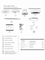
TOOLS REQUIRED
INSTALLATION PREPARATION
03
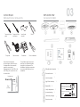
EXPLODED VIEW
PACKAGE CONTENTS
Flat-head
screwdriver
Cross-head
screwdriver
Safety glasses Pliers
Wire cutters Electrical tape Stepladder Wire strippers
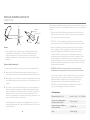
10'
(3.05 m)
30"
(76 cm)
To prevent personal injury and
damage, ensure that the hanging
location allows the blades a
clearance of 10' (3.05 m) from the
floor and 30" (76 cm) from any wall
or obstruction.
This fan can be mounted as a
flushmount on a regular (no-slope)
ceiling only. Downrod installations
are not available for this fan.
blade edge
2 wood screws with at washers
2 5/32” screws with lock washers
1 extra blade bracket screw with
spring washer
16 blade screws with washers
1 “J” hook
1 zip tie
Ceiling Bracket Assembly
Decorative circle
Motor Assembly
Light Plate Assembly
Blade(ABS)
Acrylic lampshade
Accessories bag
Hardware package
Remote control
1
1
1
1
5
1
1
1
1
6

EXPLODED VIEW
PACKAGE CONTENTS
严i
/\
o:
二=二
广
@
恤o
江二]©
中。
�
,
3
Wood screws
5/32" screws

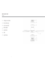
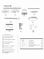
EXPLODED VIEW
DETAIL
01.
02.
03.
04.
05.
06.
07.
Ceiling mount plate
Decorative ring
Motor assembly
Blade (ABS)
Light plate
LED
Light shade
8

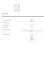
EXPLODED VIEW
DETAIL
01.
02.
03.
04.
05.
06.
07.
Ceiling Bracket Assembly
Decorative circle
Motor Assembly
Blade(ABS)
Light Plate Assembly
LED
Acrylic lampshade
03
9

11
04
ELECTRICAL SAFETY
Instructions
•
01.
02.
03.
04.
Making the Electrical Connections
•
•
•
•
•
•
•
Read all safety information and installation instructions before
you begin to install the fan and save instructions.
All set screws of the fan must be checked and re-tightened
where necessary before installation.
To reduce the risk of personal injury, do not bend the blade
brackets when installing the brackets, balancing the blades
or cleaning the fan. Do not insert foreign objects between
rotating fan blades.
Before changing the fan direction, turn off the fan and wait for
the fan blades to stop completely.
The safeguards provided by these safety instructions and by
the separate installation instructions are not meant to cover all
possible conditions and situations that may occur. It must be
understood that common sense, caution and care are factors
which can not be built into this product. These factors must be
supplied by the person(s) installing, caring for and operating
the fan.
WARNING: To avoid risk of electric shock, be sure to shut off
power at the main fuse or circuit breaker box before installing
or servicing this xture. Turning off the electrical power by using
the light switch is not sufcient to prevent electric shock.
To reduce the risk of injury, install the fan so that the blades are
at least 10' (3.05 m) above the floor and at least 30" (76 cm)
from the tip of the blades to the wall.
To reduce the risk of re, electric shock, or personal injury,
mount the outlet box marked “ACCEPTABLE FOR FAN
SUPPORT” and use mounting screws provided with the outlet
box.
The installation must be in accordance with the national
electrical code, ANSI/NFPA 70-1999 and local codes. If you
are unfamiliar with the methods of installing electrical wiring,
seek the services of a qualied licensed electrician.
WARNING: To reduce the risk of re, electric shock, or personal
injury, mount to outlet box and use mounting screws provided
with the outlet box.
IMPORTANT: Before you begin installing the fan, carefully read
all information on the separate sheet “SAFETY INSTRUCTIONS”
as well as the following “Installation Steps”. If in doubt, consult
a qualified electrician. Save all
NOTE: The fan weight is 14.537 lb(6.6 kg). Be sure the outlet box
you are using is securely attached to the building structure and
can support the full weight of the fan. Failing to do so can
result in serious injury.
10

10
ELECTRICAL SAFETY
INSTRUCTIONS
Instructions
•
01.
02.
03.
04.
Making the Electrical Connections
•
•
•
•
•
•
•
Read all safety information and installation instructions before
you begin to install the fan and save instructions.
All set screws of the fan must be checked and re-tightened
where necessary before installation.
To reduce the risk of personal injury, do not bend the blade
brackets when installing the brackets, balancing the blades
or cleaning the fan. Do not insert foreign objects between
rotating fan blades.
Before changing the fan direction, turn off the fan and wait for
the fan blades to stop completely.
The safeguards provided by these safety instructions and by
the separate installation instructions are not meant to cover all
possible conditions and situations that may occur. It must be
understood that common sense, caution and care are factors
which can not be built into this product. These factors must be
supplied by the person(s) installing, caring for and operating
the fan.
WARNING: To avoid risk of electric shock, be sure to shut off
power at the main fuse or circuit breaker box before installing
or servicing this xture. Turning off the electrical power by using
the light switch is not sufcient to prevent electric shock.
To reduce the risk of injury, install the fan so that the blades are
at least 10’ (3.05 m) above the floor and at least 30” (76cm)
from the tip of the blades to the wall.
To reduce the risk of fire, electric shock, or personal injury,
mount an outlet box marked "ACCEPTABLE FOR FAN SUPPORT"
and use mounting screws provided with the outlet box.
The installation must be in accordance with the national
electrical code, ANSI/NFPA 70-1999 and local codes. If you are
unfamiliar with the methods of installing electrical wiring, seek
the services of a qualified licensed electrician.
WARNING: To reduce the risk of fire, electric shock, or personal
injury, mount to outlet box and use mounting screws provided
with the outlet box.
IMPORTANT: Before you begin installing the fan, carefully read
all information on the separate sheet "SAFETY INSTRUCTIONS" as
well as the following "Installation Steps". If in doubt, consult a
qualified electrician.
NOTE: The fan weight is 12.34 lb (5.6 kg). Be sure the outlet box
you are using is securely attached to the building structure and
can support the full weight of the fan. Failing to do so can result
in serious injury.
11

13
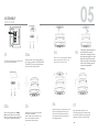
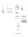
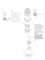
02a
Securely attach the mounting plate to
an outlet box marked "ACCEPTABLE FOR
FAN SUPPORT" using the supplied outlet
box screws with spring washers.
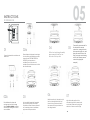
03
Assembly on flat surface advisable
for ease of installation.
Insert the decorative ring onto the
fan motor assembly and then
proceed with the next step.
05
ASSEMBLY
INSTRUCTIONS
01
Turn OFF the electric circuit at the main
fuse of circuit breaker box.
06
Hold the main body, the main body of
the four holes aligned with the four
holes of the top plate, and then fix
the screws which are pre-locked on
the ceiling bracket.
07
Align the buckle position of the
decorative ring with the screw head,
and rotate the decorative ring in the
direction of the arrow until it is tight
04
Lift the host and hang the safety
rope reserved for the host on
the hook of the top disk
05Connect the wire reserved for
the host with the remote
control wire, arrange the wire
after connecting the wire, and
place the receiver flat on the
host (for remote control wiring,
refer to the following remote
control wiring diagram
example)
12
02b
With mounting holes in the ceiling
joist, securely attach the mounting
plate to the ceiling, using the two sets
of long wood screws with washers.

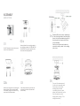
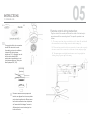
12
Turn OFF the electric circuit at the main
fuse of circuit breaker box
01 02a
Securely attach the mounting bracket to
an outlet box marked “ACCEPTABLE FOR
FAN SUPPORT” using the supplied outlet
box screws with spring washers.
02b
Drill two mounting holes in the ceiling joist.
Securely attach the mounting bracket
to the ceiling, using the two sets of long
wood screws with at washers .
03
Insert the decorative ring into the host
machine first and then proceed with
the next step
ASSEMBLY
INSTRUCTIONS
Fig. 1
04
05 Connect the wire reserved
for the motor assembly with
the remote control wire,
arrange the wire after
connecting the wire, and
place the receiver flat on the
host (for remote control
wiring, refer to page 17 for
wiring instructions).
13
Carefully lift the fan motor assembly up
to the mounting bracket and hang the
fan on the hook provided using one of
the holes at the outer rim of the fan
motor assembly.
Use the wood screw and washer to
secure the safety cable to the ceiling
joist or box.

06
Remove two of the four screws (located diagonally from each other) from the
top of the mounting plate and loosen the other two screws .
Align the two key slots in the top of the fan motor assembly with the two
loosened screws on the mounting plate. Push the fan motor assembly up and
turn it clockwise to lock in the mounting plate. Tighten the two screws on the
mounting plate.
Install the two screws that were removed at the beginning of this step into the
remaining two holes and tighten the four screws firmly.
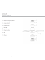
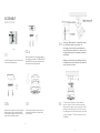
ASSEMBLY
INSTRUCTIONS
14

08
Attach a blade to the fan motor
assembly by inserting the blade into
slots in the side of the fan motor
assembly and aligning the three
screws holes in the blade with the
holes in the center flywheel and
secure with screws. Make sure all the
screws are firmly tightened. Repeat
these steps for the remaining blades.
Attach light plate to motor assembly
with light plate screws
1115
Install the decorative
ring by aligning
the ring's slots with the
screws on the mounting
plate. Rotate the ring
clockwise to lock in
place.
0708 Attach a blade to the fan motor
assembly by inserting the blade into
slots in the side of the fan motor
assembly and aligning the three
screws holes in the blade with the
holes in the centre flywheel and
secure with screws. Make sure all the
screws are firmly tightened. Repeat
these steps for the remaining blades.
Note: Ensure that the blade side
indicated "This side up" is facing the
ceiling for correct blade installation.
09

15
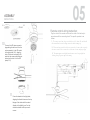
05
ASSEMBLY
INSTRUCTIONS
Connect the LED wires connector
plug exiting the bottom of the fan
motor assembly to the LED socket
of the light plate (10-1), align the
hole of the main connecting LED,
and lock the screws which are pre-
locked on the host to fix the LED
plate (10-2).
Place the shade into the light plate,
aligning the three flat areas on the top
flange of the shade with the raised
dimples in the light kit pan. Turn the
shade clockwise until it stops and is
secure.
Remote control wiring instruction:
Plug the outlet of the remote control and the outlet of the fan body in
accordance with the connecting head. The specific operation is as
follows:
1、The remote control into the power is black or red (L), white (N), and the wall
of the neutral line, live wire docking, connected with the wiring cap
2、The motor line reserved for the host is connected to the motor line output by
the remote control. Red is connected to red, brown to brown, and gray to gray
3、The main engine reserved light line and remote control output light line
docking, direct plug can complete the wiring
16
10-1 10-2
10
11

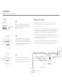
14
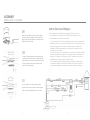
ASSEMBLY
INSTRUCTIONS - CONTINUED
08
Insert the fan blade into the host hole, tighten
the screws with the washers, and repeat this
step for the remaining blades (note that the fan
blade has only one side).
09
Connect the lamp connection line reserved by
the host and the LED socket of the lamp plate,
align the hole of the main connecting plate, and
lock the screws which are pre-locked on the
host to fix the lamp plate
10
The notch position of acrylic lampshade is
aligned with the convex point of the lamp plate,
rotate the acrylic lampshade until it is fasten.
Wiring instructions:
Plug the outlet of the remote control and the outlet of the fan
body in accordance with the connecting head. The specific
operation is as follows:
1. Connect the black wire (L) on the receiver with the live wire from
the outlet box, and connect the white wire (N) on the receiver with
the neutral wire from the outlet box. Connect them by twisting
frayed ends together, using wire connectorsto fasten them.
2. The motor wires from the fan are connected to the motor wire
output from the remote control. Red is connected to red, brown to
brown, and grey to grey. Connect green wire from the fan with the
ground wire from the outlet box.
3. Connect the light wires (blue and white wires set in one quick
connector) from the motor with the blue and white wires (set in one
quick connector) from the receiver. The wiring is complete.
17

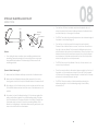
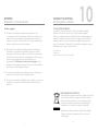
INSTRUCTIONS FOR REMOTE
18
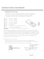
OPERATING THE FAN:
A. Install 2 x 1.5 V AAA battery (included). To prevent damage to
the remote, remove the batteries if not used for a long time.
B. Store the remote away from excessive heat or humidity.
C. Operation of the buttons on the panel of the remote:
key — for fan 1 speed
key — for fan 2 speed
key — for fan 3 speed
key — for fan 4 speed
key — for fan 5 speed
key — for fan 6 speed
key — for fan off
key — for light colour, dimming and on/off
key — for fan Foward/Reverse
key — stops the fan after set time elapsed
Press and release light key one time to turn light on or off or switch light
colour. Long press light key when the light is on, it will activate the dimmer
function and the light varies from the current brightness to brighter, or dark
to bright circulatory. User can switch to another light colour and repeat this
step to dim each light colour. When the light is turned on again,the light
memory function will resume the light setting (colour and brightness)
before the light was turned off.
D. Pairing the remote control:
Power off the receiver for five minutes. Turn on the power and
immediately press and hold the key of LIGHT and SPEED3 until the light
turns on, indicating the receiver is paired to the remote.

19
07
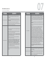
TROUBLESHOOTING
COMMON PROBLEMS
PROBLEMPROBLEM SOLUTIONSSOLUTIONS
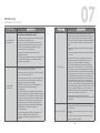
Fan does not start
•CAUTION: Make sure main power is turned off.
• Check main and branch circuit fuses or circuit
breakers.
•Make sure forward/reverse switch is firmly in left or
right position. Fan will not operate when switch is in
the middle.
• Make sure that the wall control is turned "ON".
• Check line wire connections to fan and switch wire
connections in switch housing.
Fan sounds noisy
• Make sure all screws in motor housing are snug (not
over-tightened).
• Make sure the screws which attach the fan blade
bracket to the motor are tight.
• Make sure wire nut connectors in switch housing are
not rattling against each other or against the interior
wall of the switch housing.
•
•
CAUTION: Make sure power is turned off before
accessing switch housing.
• Some fan motors are sensitive to signals from solid
state variable speed controls. DO NOT USE a solid
state variable speed control.
• Allow "break-in" period of 24 hours. Most noises
associated with a new fan will disappear after this
period.
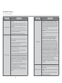
PROBLEMPROBLEM SOLUTIONSSOLUTIONS
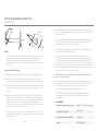
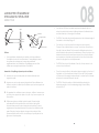
Fan wobbles
•All blades are weighed and grouped by weight.
Natural woods vary in density which could cause the
fan to wobble even though all blades are weight-
matched. The following procedures should eliminate
most of the wobble. Check for wobble after each
step.
•Check that all blades are screwed rmly into blade
brackets.
• Check that all blade brackets are tightened securely
to motor.
• Make sure that canopy and hanger bracket are
tightened securely to ceiling junction box and
junction box is mounted rmly to ceiling joist.
•Most wobble problems of fan are caused when
blades are not in equal level. To check the blade
levels, select a point on the ceiling above the tip of
any blade. Measure the distance from the ceiling to
the blade tip, to an accuracy of 1/8” (3 mm). Rotate
the blades until the next blade is in the measuring
position. Repeat measurement for each blade. If all
blade levels are not equal, you can adjust blade
levels by the following procedure. To adjust a blade
tip down, insert a washer (not supplied) between the
blade and blade bracket at the screw closest to the
motor. To adjust a blade tip up, insert washer (not
supplied) between the blade and blade bracket at
the two screws farthest from the motor.
•Interchanging two adjacent blades could
redistribute the weight and possibly result in smoother
operation.
Light does not work
•Check the blue wire from fan to make sure it is
connected to hot wire from supply wire coming out
of the ceiling.
•Check for loose or disconnected wires in fan switch
housing.
• Check for loose or disconnected wires in light kit.
•Check for faulty light bulbs.
19
If using an optional ceiling fan light kit, make
sure the screws securing the glassware are
finger-tight. Make sure light bulbs are tight in
sockets and not touching glass shade(s).

18
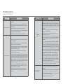
TROUBLESHOOTING
COMMON PROBLEMS
PROBLEM
PROBLEM
SOLUTIONS
SOLUTIONS
Fan does not start
•Check main and branch circuit fuses or circuit
breakers.
•Make sure forward/reverse switch is rmly in left or
right position. Fan will not operate when switch is in
the middle.
•Make sure that the wall control is turned “ON”.
•Check line wire connections to fan and switch wire
connections in switch housing.
• CAUTION: Make sure main power is turned off.
Fan sounds noisy
•Make sure all screws in motor housing are snug (not
over-tightened).
• Make sure the screws which attach the fan blade
bracket to the motor are tight.
• Make sure wire nut connectors in switch housing are
not rattling against each other or against the interior
wall of the switch housing.
•CAUTION: Make sure power is turned off before
accessing switch housing.
• If using an optional ceiling fan light kit, make sure the
screws securing the glassware are nger-tight. Make
sure light bulbs are tight in sockets and not touching
glass shade(s). If vibration persists from glass, remove
glass and install a 1/4”-wide (6 mm) rubber band on
glass neck to act as an insulator. Replace glass and
tighten screws against rubber band.
• Some fan motors are sensitive to signals from solid
state variable speed controls. DO NOT USE a solid
state variable speed control.
•Allow “break-in” period of 24 hours. Most noises
associated with a new fan will disappear after this
period.
PROBLEM
PROBLEM
SOLUTIONS
SOLUTIONS
Fan wobbles
• All blades are weighed and grouped by weight.
Natural woods vary in density which could cause the
fan to wobble even though all blades are weight-
matched. The following procedures should eliminate
most of the wobble. Check for wobble after each
step. Refer page 8
•Check that all blades are screwed firmly into blade
brackets.
• Check that all blade brackets are tightened securely
to motor.
• Interchanging two adjacent blades could
redistribute the weight and possibly result in smoother
operation.
Light does not work
•Check the blue wire from fan to make sure it is
connected to hot wire from supply wire coming out
of the ceiling.
•Check for loose or disconnected wires in fan switch
housing.
• Check for loose or disconnected wires in light kit.
•Check for faulty light bulbs.
20
•Make sure that canopy and hanger bracket are
tightened securely to ceiling junction box and
junction box is mounted firmly to ceiling joist.
•Most wobble problems of fan are caused when
blades are not in equal level. To check the blade
levels, select a point on the ceiling above the tip of
any blade. Measure the distance from the ceiling to
the blade tip, to an accuracy of 1/8" (3 mm). Rotate
the blades until the next blade is in the measuring
position. Repeat measurement for each blade. If all
blade levels are not equal, you can adjust blade
levels by the following procedure. To adjust a blade
tip down, insert a washer (not supplied) between the
blade and blade bracket at the screw closest to the
motor. To adjust a blade tip up, insert washer (not
supplied) between the blade and blade bracket at
the two screws farthest from the motor.
La page charge ...
La page charge ...
La page charge ...
La page charge ...
La page charge ...
La page charge ...
La page charge ...
La page charge ...
La page charge ...
La page charge ...
La page charge ...
La page charge ...
La page charge ...
La page charge ...
La page charge ...
La page charge ...
La page charge ...
La page charge ...
La page charge ...
La page charge ...
La page charge ...
La page charge ...
La page charge ...
La page charge ...
La page charge ...
La page charge ...
La page charge ...
La page charge ...
La page charge ...
La page charge ...
La page charge ...
-
 1
1
-
 2
2
-
 3
3
-
 4
4
-
 5
5
-
 6
6
-
 7
7
-
 8
8
-
 9
9
-
 10
10
-
 11
11
-
 12
12
-
 13
13
-
 14
14
-
 15
15
-
 16
16
-
 17
17
-
 18
18
-
 19
19
-
 20
20
-
 21
21
-
 22
22
-
 23
23
-
 24
24
-
 25
25
-
 26
26
-
 27
27
-
 28
28
-
 29
29
-
 30
30
-
 31
31
-
 32
32
-
 33
33
-
 34
34
-
 35
35
-
 36
36
-
 37
37
-
 38
38
-
 39
39
-
 40
40
-
 41
41
-
 42
42
-
 43
43
-
 44
44
-
 45
45
-
 46
46
-
 47
47
-
 48
48
-
 49
49
-
 50
50
-
 51
51


NOMA Hayden 3-Reversible Blade 6-Speed Le manuel du propriétaire
- Catégorie
- Ventilateurs ménagers
- Taper
- Le manuel du propriétaire
Documents connexes
-
NOMA Milton 5-Reversible blade 6-Speed Le manuel du propriétaire
-
-
-
-
-
Autres documents
-
LIVARNO 359555 Le manuel du propriétaire
-
for Living 3-Reversible Blade 3-Speed Le manuel du propriétaire
-
-
-
 Kichler Lighting Motu Manuel utilisateur
-
Create Wind Calm Ceiling Fan Manuel utilisateur
-
ETS SolarForce 652V Manuel utilisateur
