Minebea Intec Option A15. Analog/Digital Converter for Connecting a Reference Scale Le manuel du propriétaire
- Taper
- Le manuel du propriétaire

98647-004-26
98647-004-26
Installation Instructions | Installationsanleitung | Notice d’installation |
Istruzioni per l’installazione | Instrucciones de instalación
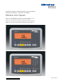
Minebea Intec Signum
Option A15. Analog/Digital Converter for Connecting a Reference Scale
Option A15. AD-Wandler für Mengenwaagenanschluss (ADU)
Option A15. Connexion pour balance de référence (convertisseur A/N)
Opzione A15. Connessione per bilancia di riferimento (convertitore A/D)
Opción A15. Conexión para báscula de referencia (convertidor A/D)

2 Signum Option A15 Signum Option A15 3
English – page 3
Deutsch – Seite 23
Français – page 42
Italiano – pagina 61
Español – página 80

2 Signum Option A15 Signum Option A15 3
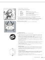
Intended Use Contents
– This additional, powerful analog/digital
converter enables the use of a second
weighing point; e.g., for connecting
a weighing platform with a broad
weighing range
– Connect the reference scale to the
display and control unit with a cable
gland, or install a separable plug-in
connector
– Operator-guided configuration of
reference scale in the operating menu
– Also available for use in legal metrology;
reference scale configurable in class
III up to 6250e and in class IIII up to
1000e
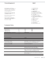
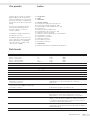
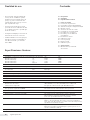
Specifications
Maximum readability 15,000 display digits (not in legal metrology)
Maximum permissible verification scale intervals Accuracy class l m
Single-range mode n< 6250e 1000e
Multiple-range mode ni< 3125e 1000e
Multi-interval scale ni< 3125e 1000e
Multi-interval scale Max/ei< 6250e 6250e
Digital protective interface In accordance with EN 45501
Load cell supply voltage Uexc 8.4 VDC
Minimum input voltage per Umin 0.672 µV
verification scale interval
Minimum/maximum load resistance RLmin to RLmax 83 O to 2000 O
Limits of temperature range TLmin to TLmax –10°C to +40°C (+14°F to +104°F)
Fraction of the maximum permissible error ρi 0.5
Type of cable connection 6-conductor
Max. value of cable length per (L/A) 150 m/mm2
wire cross section
Range of input voltage Umin to Umax 0 to 29.4 mV
Ratings:
Power supply 100-240 VAC (–15/+10%), 50-60 Hz, max. 17 W/23 VA
Transient overvoltage Overvoltage category II in accordance with IEC 60364-4-443
Operation using protective extra-low voltage
with safe separation from wall outlet (PELV) See instruction manual for Option L8
DC power supply 22.8 to 26.7 V (optional: 21.6 to 26.7 V); max. 12 VA
AC power supply 22.8 to 26.7 V, 50-60 Hz, max. 12 VA
Operation with rechargeable battery See instruction manual for Option L9
Battery operation using built-in or external rechargeable battery
(must be included in initial order)
Limitation of emissions In accordance with EN 61326-1 (IEC 61326-1):
Group 1, Class B, suitable for use in domestic establishments and
establishments directly connected to a low-voltage power-supply
network that supplies buildings used for domestic purposes
Immunity to interference In accordance with EN 61326-1 (IEC 61326-1):
Immunity test requirements for equipment intended for use in
industrial locations (Table 2)
Electrical safety In accordance with EN 61010-1 (IEC 61010-1)
3 Intended Use
3 Specifications
4 Getting Started
4 Connecting the Weighing Platform
7 Configuring the Analog/Digital
Converter
8 A/D Converter Configuration Menu
10 Service Menu
11 Activating the Service Mode
12 Selecting the Configuration Mode
15 Entering Geographical Data
16 Entering Calibration/Adjustment and
Linearization Weights
17 External Linearization
18 Calibration and Adjustment
20 Setting the Preload
20 Clearing the Preload
20
Calibration/Adjustment without Weights
Configuration
21 Reference Scale Operating Menu

4 Signum Option A15 Signum Option A15 5
Getting Started
Connecting the Weighing Platform
Connection of an analog Minebea Intec MAPP or MAPS platform or of a commercially
available strain-gauge load cell is described in the following.
! The load cell should be connected only by a trained and authorized Minebea Intec tech-
nician. Any installation work that does not conform to the instructions in this manual
will result in forfeiture of all claims under the manufacturer’s warranty.
! Disconnect the equipment from power (unplug from the wall socket) before beginning
any installation work.
§ Set up the weighing platform (see the operating instructions for the weighing platform)
§ Lay the cable for connecting the weighing platform to the display and control unit
§ Open the Signum display and control unit:
remove the four cap nuts from the front panel and remove the panel.
§ Connect cable from the weighing platform to the display and control unit
Note:
The cable gland is installed at the factory. Please use extreme caution when performing
any work on the equipment that affects this cable gland.
Use a torque wrench and tighten the cable gland to 5 Nm.
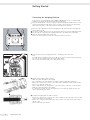
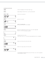
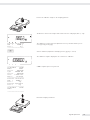
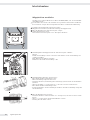
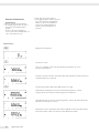
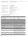
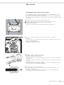
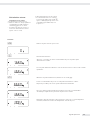
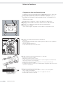
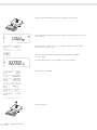
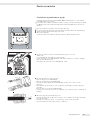
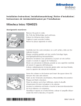
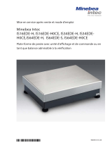
§ Prepare and install the cable as follows.
– Guide the cable through the cable gland.
– Close and tighten the cable gland in accordance with the applicable regulations.
– Remove the casing from a section of the cable end (see illustration). The shield (1) must
have contact with the clamps (2).
– Expose approximately 15 cm (4 inches) of the wires (3) for connection to the terminals.
– Guide the cable through the cable gland.
– It is important to make sure that the shield is in contact with the clamps, because the
cable is grounded by the shield.
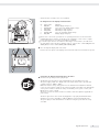
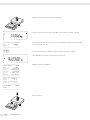
§ Install the weighing platform cable as follows:
– Remove the casing from a section of the cable end. Expose approximately 5 cm (2 inches)
of the isolated wires for installation.
– Remove the casing from approximately 1 cm (1/2 inch) of the wires and attach ferrules to
the wire ends.
– Fit the ferrite ring over all wires.

4 Signum Option A15 Signum Option A15 5
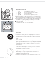
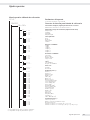
– Attach the wires securely to the screw terminals
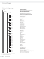
Pin Assignments in the Display and Control Unit
No. Signal name Meaning
1 BR_POS Bridge supply voltage (+)
2 SENSE_POS Sense (+) for the bridge supply voltage
3 OUT_POS Measuring voltage positive
4 OUT_NEG Measuring voltage negative
5 SENSE_NEG Sense (-) for bridge supply voltage
6 BR_NEG Bridge supply voltage (-)
! Please refer to the service specifications or operating instructions for the load cell or
weighing platform in question for details on the assignment of wire colors to signals.
Isolate unused wires in accordance with industry standards.
! If a load receptor that uses 4-conductor technology is connected (i.e., the cable from
the load cell has only four wires), add wire straps to connect wires 1 and 2 (BR_POS and
SENSE_POS) to wires 5 and 6 (SENSE_NEG and BR_NEG).
§ Close the Signum display and control unit:
Position the front panel on the display and control unit and fasten it with the 4 cap nuts
Connecting the Display and Control Unit to AC Power
§ Check the voltage rating and the plug design.
$ The display and control unit is powered through the pre-installed power cord.
The power supply is built into display and control unit, which can be operated with
a supply voltage of 100 V to 240 V.
Make sure that the voltage rating printed on the manufacturer’s ID label is identical
to that of your local line voltage. If the voltage specified on the label or the plug design
of the power cord do not match the rating or standard you use, please contact your
Minebea Intec office or dealer.
The power connection must be made in accordance with the regulations applicable in
your country.
The device (protection class 1) must be plugged into a properly installed wall outlet
which has a protective grounding conductor (PE) and a fuse with maximum 16A.
The power plug or other suitable device for disconnecting the power must be easily
accessible.

6 Signum Option A15 Signum Option A15 7
Safety Precautions
If you use an electrical outlet that does not have a protective grounding conductor,
make sure to have an equivalent protective conductor installed by a certified electrician
as specified in the applicable regulations for installation in your country. Make sure the
protective grounding effect is not neutralized by use of an extension cord that lacks
a protective grounding conductor.
NOTE:
This equipment has been tested and found to comply with the limits pursuant to part 15
of FCC Rules. These limits are designed to provide reasonable protection against harmful
interference. This equipment generates, uses and can radiate radio frequency energy and,
if not installed and used in accordance with these instructions, may cause harmful inter-
ference to radio communications. For information on the specific limits and class of this
equipment, please refer to the Declaration of Conformity. Depending on the particular
class, you are either required or requested to correct the interference. If you have a Class A
digital device, you need to comply with the FCC statement as follows:
“Operation of this equipment in a residential area is likely to cause harmful interference
in which case the user will be required to correct the interference at his own expense.”
If you have a Class B digital device, please read and follow the FCC information given
below:
“[...]However, there is no guarantee that interference will not occur in a particular instal-
lation. If this equipment does cause harmful interference to radio or television reception,
which can be determined by turning the equipment off and on, the user is encouraged to
try to correct the interference by one or more of the following measures:
– Reorient or relocate the receiving antenna.
– Increase the distance between the equipment and receiver.
– Connect the equipment into an outlet on a circuit different from that to which the
receiver is connected.
– Consult the dealer or an experienced radio/TV technician for help.”
Before you operate this equipment, check which FCC class (Class A or Class B) it has
according to the Declaration of Conformity included. Be sure to observe the information
of this Declaration.
Warmup Time
To deliver exact results, the display and control unit must warm up for at least
30 minutes after initial connection to AC power or after a relatively long power outage.
Only after this time will the equipment have reached the required operating temperature.
Using Verified Equipment in Legal Metrology
$ Make sure to allow the equipment to warm up for at least 6 hours after initial connection
to AC power.

6 Signum Option A15 Signum Option A15 7
Configuring the
Analog/Digital Converter
Purpose
To adapt the parameters of the analog/
digital converter to the connected load
cell or weighing platform. Once these
parameters have been configured, the
A/D converter in conjunction with
the load cell is defined as a weighing
instrument.
Notes on Settings
– The A/D converter can be configured
only with the menu access switch
open (see “Selecting the Configuration
Mode”). Make sure you close the menu
access switch following A/D converter
(ADC) configuration; otherwise, the
“overload” (H) and “underload” (L) error
codes are not shown.
– To enable ADC configuration, activate
the service mode (see “Service Mode”),
open the Setup menu, open the COM-
SPEC submenu, and select ADC-CON.
– Enter the maximum capacity (max. cap.)
in a suitable weight unit, without deci-
mal places (the rounding function will
truncate any decimal places).
! If you return to the highest menu level
without selecting the SAVE menu item
to save changes, all changes made up
to that point are discarded.
– The menu-reset function (“Restore
Factory Settings”) does not affect
settings for ADC configuration.
! Note:
Once the ADC configuration has been
locked (menu access switch closed), the
display and control unit can no longer
be used to influence weighing results.
The scope of functions available in the
weighing instrument is defined by the
A/D converter. Weighing functions that
can be activated include: read weight
value, tare, calibrate/adjust, read tare
value, save/delete tare input
Descriptions of Menu Items
for A/D Converter Configuration
Standard or Verified Configuration
(Menu Items: STAND. / VERIF.)
Before configuring the A/D converter,
you must define whether the weighing
platform is to be used in “standard”
mode or “verified” mode (verified for
use in legal metrology).
– Standard mode: STAND.
– Verified mode: VERIF.
Accuracy Class (Menu Item: CLASS)
Shown only for configuration in
“verified” mode.
Only menu items 3 and 4 (accuracy
class l/m) are accessible. If the
desired menu item is not marked with
a circle (o) indicating it is already active,
press ) repeatedly until this menu
item is activated.
Selecting the Weighing Range (Menu
Item: RANGES)
This setting defines whether the RANGE
1, RANGE 2 and RANGE 3 menu items
for further configuration steps are
shown or hidden.
– Single-range mode (SINGLE):
The entire weighing range is divided
into scale intervals on the basis of the
lowest interval d and the maximum
load. Readability is equal to scale inter-
val d (see below).
– Multi-interval mode (MULT.Int.):
The “Multi-interval” function divides
the weighing capacity into as many as
3 weighing ranges, each with a different
readability. The scale switches from
one range to the next automatically,
in accordance with the range limits
specified. Once the instrument has been
tared, the best possible resolution
(lowest display digit) is available even
when there is a load on the weighing
platform.
– Multiple-range mode (MULT.-R.):
A multiple-range scale has two or three
weighing ranges. When the maximum
capacity of a lower range is exceeded,
the scale switches to a higher range
(lower resolution). The scale can be
returned to the higher resolution only
after the scale has been unloaded.
Scale Interval d
The display digit, d, indicates the
resolution of the weighing instrument.
The display digit can be entered only in
increments of 1, 2, 5, 10, 20, 50, etc.
This menu item is not shown when
the “verified” configuration mode is
active. On verifiable or verified weighing
instruments (class l and m) scale
interval d is equal to verification scale
interval e.
Verification Scale Interval e
The verification scale interval e indi-
cates the resolution of the weighing
instrument in legal metrology. The scale
interval d can be entered only in incre-
ments of 1, 2, 5, 10, 20, 50, etc.
This menu item is not shown when
the “standard” configuration mode is
active.
Maximum Capacity (Max. Cap.)
The maximum capacity is the maxi-
mum load that may be placed on the
weighing instrument. If a heavier load
is placed on the platform, the display
shows “H.”
The scale intervals are calculated from
the maximum capacity and the scale
interval d. For example, a maximum
capacity of 15,000 kg with a smallest
scale interval d of 0.005 kg yields
3000 scale intervals.
Maximum readability:
15,000 display digits (not in legal
metrology).
In legal metrology, the number
of intervals must not exceed 3125 e;
for multi-interval scales, the limit is
3125 e per range.

8 Signum Option A15 Signum Option A15 9
Range 1, Range 2, Range 3
(RANGE 1, RANGE 2, RANGE 3):
Here you can enter the limits for each
of the weighing ranges. When a limit is
exceeded, the accuracy changes.
The following applies when entering
range limits:
Range 1 < range 2 < range 3 < max.
cap.
Thus the weighing capacity can be
divided into 4 ranges. The display reso-
lution changes in intervals of 1, 2, 5,
10, 20 etc. The lowest resolution is the
smallest scale interval d. Ranges you do
not require should be set to 0.
Available Weight Units (Menu Item:
UNITS)
The weight units available for use in
the normal weighing mode are selected
here. Available units are indicated by
a circle (o) on the display (more than
one can be selected).
When using the instrument in legal
metrology, make sure the selected unit
is permissible.
Saving Configuration Parameters
(Menu Item: SAVE)
Once you have selected all required
parameters, select the SAVE menu item
to store the settings.
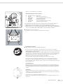
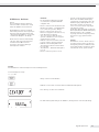
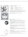
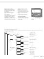
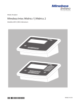
Checking and Configuring the Equip-
ment for Use in Legal Metrology
A metrological ID tag is included with
the display and control unit.
Following ADC configuration, write
the metrological data on this tag for all
weighing ranges. Affix this tag below
the display and cover it with the water-
proof acetate overlay.
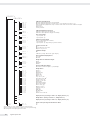
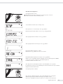
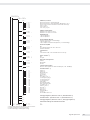
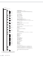
Info
n
Scale
#
Zero
0
Tare
T
Function
Fn
Print
ISO-
Test
On
Standby
Resolution
x10
NET
B/G
CF
Clear
Function
Toggle
Reference
REF OK
Signum2
A
Check the settings under menu item 1.7
to make sure only the permitted weight
units are accessible.
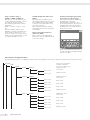
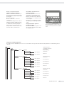
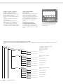
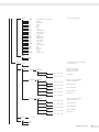
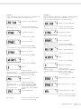
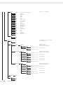
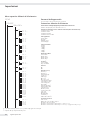
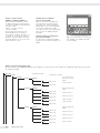
A/D Converter Configuration Menu
The following menu items for configuring the A/D converter are appended to the COMSPEC numeric menu when the service mode is active:
ADU-CON A/D converter configuration
STAND. Standard configuration
RANGES Selection of weighing ranges
SINGLE WEIGHTS Single-range mode
D Scale interval
Enter a value
MAX Maximum capacity
Enter a value
MULT.Int. WEIGHTS Multi-interval mode
D Scale interval
Enter a value
RANGE 1 Range 1 limit
Enter a value
RANGE 2 Range 2 limit
Enter a value
RANGE 3 Range 3 limit
Enter a value
MAX Maximum capacity
Enter a value
MULT.-R. WEIGHTS Multiple range mode
D Scale interval
Enter a value
RANGE 1 Range 1 limit
Enter a value
RANGE 2 Range 2 limit
Enter a value
RANGE 3 Range 3 limit
Enter a value
MAX Maximum capacity
Enter a value

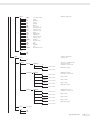
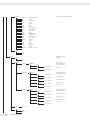
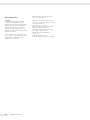
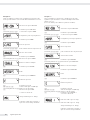
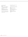
8 Signum Option A15 Signum Option A15 9
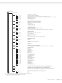
UNITS Available weight units
FREE User-defined unit
G Grams
KG Kilograms
CT Carats
LB Pounds
OZ Ounces
OZT Troy ounces
TLH Hong Kong taels
TLS Singapore taels
TLT Taiwanese taels
GN Grains
DWT Pennyweights
MG Milligrams
/LB Parts per pound
TLC Chinese taels
MOM Mommes
K Austrian carats
TOL Tola
BAT Baht
MS Mesghal
T Tons
LB/OZ Pounds and ounces
SAVE
NO
YES
VERIF. Verified configuration
CLASS Accuracy class
3/4
RANGES Selection of weighing ranges
SINGLE WEIGHTS Single-range mode
E Verification scale interval
Enter a value
MAX Maximum capacity
Enter a value
MULT.INT. WEIGHTS Multi-interval mode
E Verification scale interval
Enter a value
RANGE 1 Range 1 limit
Enter a value
RANGE 2 Range 2 limit
Enter a value
RANGE 3 Range 3 limit
Enter a value
MAX Maximum capacity
Enter a value
MULT.R. WEIGHTS Multiple range mode
E Verification scale interval
Enter a value
RANGE 1 Range 1 limit
Enter a value
RANGE 2 Range 2 limit
Enter a value
RANGE 3 Range 3 limit
Enter a value
MAX Maximum capacity
Enter a value
UNITS (See above)
SAVE
NO
YES

10 Signum Option A15 Signum Option A15 11
Service Menu
Purpose
The service menu contains additional
configuration options in the operating
menu (Setup) that are only available
when the ”Service“ mode is active.
The service menu must be activated to
enable the main calibration/adjustment
operations affecting the display and
control unit and the connected
weighing platform.
When the service mode is active, an “S”
is shown in the upper right-hand corner
of the display. To deactivate the service
mode, switch the display and control
unit off and then on again.
The following menu items are appended
to the “Date” (DATE) and “Password”
(CODE) menu items:
– S-DATE: Date of service
(enter the next scheduled service date)
– MEM-NO: Memory number
(enter a transaction number for an
external Alibi memory)
– SER-NO: Display and control unit serial
number
– model: Model designation
(enter the device serial number)

10 Signum Option A15 Signum Option A15 11
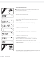
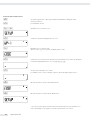
Activating the Service Mode
e Switch on the display and control unit and press )
) briefly, during the startup routine, to open the operating menu
k k Select the Setup menu item
) Open the Setup menu1
k Select the Code menu item
(Press k repeatedly until code is displayed)
) Open the Code submenu and enter the service access code (see Appendix)
Enter the code using the ( ) k p keys
) Confirm the service access code
Service mode is active: an “S” is shown in the upper right-hand corner of the display.
( Return to the “Code” menu, now in service mode.
( Return to the “Setup” menu, now in service mode.
1 If password input is prompted at this point, enter the service access code (see appendix)
and confirm input to continue
setup
wp-1
code
code

12 Signum Option A15 Signum Option A15 13
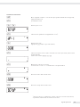
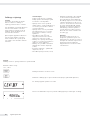
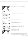
Selecting the Configuration Mode
Open the menu access switch:
§ Remove the cap that covers the menu access switch on the left-hand side of the back
of the display and control unit housing
§ Move the switch to the left (“menu accessible” position)
Activate the service mode (see previous page)
) Confirm Setup menu: press )
k k )
Select the “Reference scale” menu item (COMSPEC) and confirm: press k twice,
and then press )
k Select the “Analog/digital converter” menu item (ADU-232): press k
) Confirm the ADU-232 menu item: press )
k repeatedly Select the “ADC configuration” menu item (ADC-CON): press k repeatedly
) Confirm the ADC-CON menu item: press )
Select the “Standard” (STAND.) or “Verified“ (VERIF.) configuration mode.
In this example, “Standard” is selected.
Subsequent configuration steps are illustrated in detail on the next two pages.
Following configuration, select the SAVE menu item to save your settings.
The A/D converter, in conjunction with the weighing platform, can now be used like any
standard weighing platform.
Close the menu access switch
Following ADC configuration, calibration/adjustment and linearization must be performed
on the weighing platform (see page 18, “Calibration and Adjustment,” and page 20,
“Calibration and Adjustment without Weights” for details).
ADC-CON
STAND.
SAVE

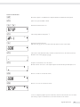
12 Signum Option A15 Signum Option A15 13
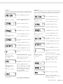
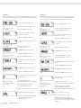
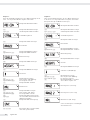
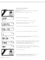
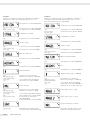
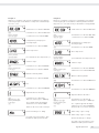
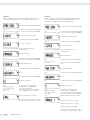
Example 1:
Entering/modifying values, in the weights units defined under menu
item 1.7.x, for a single-range scale in “Standard” configuration mode.
ADC-CON
Select the ADC-CON menu item
) Confirm the ADC-CON menu item
(press k as needed) Select the STAND. menu item
Stand.
Standard configuration mode
) Confirm the STAND. menu item
Ranges
The RANGES menu item is shown
) Confirm the RANGES menu item
(press k repeatedly
if necessary) Select the SINGLE menu item
SINGle
The “Single range scale” menu item
is shown
( Confirm the SINGLE menu item
Weights
The WEIGHTS menu item is shown
) Confirm the WEIGHTS menu item
d
The “Scale interval” menu item (D)
is shown
) Confirm the D menu item
( ) k p Enter the desired value (e.g., 0.002 kg)
(press ) repeatedly
if necessary) Display the D menu item again
k Select the MAX. menu item
max.
The “Maximum capacity” menu item
is shown
) Confirm the MAX. menu item
( ) k p Enter the desired value (e.g., 30 kg)
(press ) repeatedly
if necessary) Display the MAX. menu item again
( The UNITS menu item is shown
(press ) as needed) Select the “Available weight units”
menu item (UNITS)
k The SAVE menu item is shown
Save
) k ) Save the values entered (YES)
or quit without saving values (NO)
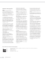
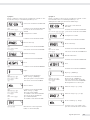
Example 2:
Entering/modifying values, in the weights units defined under menu
item 1.7.x, for a multi-interval scale in “Standard” configuration mode.
(The procedure for configuring a multiple range scale is similar.)
ADC-CON
Select the ADC-CON menu item
) Confirm the ADC-CON menu item
(press ) k p
as needed) Select the STAND. menu item
Stand.
Standard configuration mode
) Confirm the STAND. menu item
Ranges
The RANGES menu item is shown
) Confirm the RANGES menu item
(press k repeatedly
if necessary) Select the MULT.INT. menu item
Mult.Int
The “Multi-interval scale” menu item
is shown
( Confirm the MULT.INT. menu item
Weights
The WEIGHTS menu item is shown
) Confirm the WEIGHTS menu item
d
The “Scale interval” menu item (D) is
shown
) Confirm the D menu item
( ) k p Enter the desired value (e.g., 0.002 kg)
(press ) repeatedly
if necessary) Display the D menu item again
k Select the RANGE 1 menu item.
Follow this procedure to enter
values for:
Range 1
Limit for range 1 (e.g., 6 kg)
Range 2
Limit for range 2 (e.g., 15 kg)
max.
Maximum capacity (e.g., 30 kg)
Continue as described under
Example 1, after the step for entering
the maximum capacity

14 Signum Option A15 Signum Option A15 15
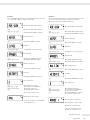
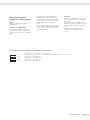
Example 3:
Entering/modifying values, in the weights units defined under menu
item 1.7.x, for a single-range scale in “Verified” configuration mode.
ADC-CON
Select the ADC-CON menu item
) Confirm the ADC-CON menu item
(press ) k p
as needed) Select the VERIF. menu item
Verif.
The “Verified configuration mode”
menu item is shown
) Confirm the VERIF. menu item
Class
The “Verification class” menu item
is shown
(press ) ) (
as needed) Confirm “Accuracy class 3”
or “Accuracy class 4”
Ranges
The RANGES menu item is shown
) Confirm the RANGES menu item
(press k repeatedly
if necessary) Select the SINGLE menu item
SINGle
The “Single range scale” menu item
is shown
( Confirm the SINGLE menu item
Weights
The WEIGHTS menu item is shown
) Confirm the WEIGHTS menu item
E
The “Verification scale interval” menu
item (E) is shown
) Confirm the E menu item
( ) k p Enter the desired value (e.g., 0.002 kg)
(press ) repeatedly
if necessary) Display the E menu item again
k Select the MAX. menu item
Follow this procedure to enter values for:
max.
Maximum capacity (e.g., 30 kg)
Continue as described under Example 1,
after the step for entering the
maximum capacity
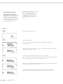
Example 4:
Entering/modifying values, in the weights units defined under menu
item 1.7.x, for a multi-interval scale in “Verified” configuration mode.
(The procedure for configuring a multiple range scale is similar.)
ADC-CON
Select the ADC-CON menu item
) Confirm the ADC-CON menu item
(press ) k p
as needed) Select the VERIF. menu item
Verif.
The “Verified configuration mode”
menu item is shown
) Confirm the VERIF. menu item
Class
The “Verification class” menu item
is shown
(press ) ) (
as needed) Confirm “Accuracy class 3/4”
Ranges
The RANGES menu item is shown
) Confirm the RANGES menu item
(press k repeatedly
if necessary) Select the MULT.INT. menu item
Mult.Int
The “Multi-interval scale” menu item is
shown
( Confirm the MULT.INT. menu item
Weights
The WEIGHTS menu item is shown
) Confirm the WEIGHTS menu item
E
The “Verification scale interval” menu
item (E) is shown
) Confirm the E menu item
( ) k p Enter the desired value (e.g., 0.002 kg)
(press ) repeatedly
if necessary) Display the E menu item again
k Select the RANGE 1 menu item
Follow this procedure to enter values for:
Range 1
Limit for range 1 (e.g., 6 kg)
Limit for range 2 (e.g., 15 kg)
Maximum capacity (e.g., 30 kg)
Continue as described under Example 1,
after the step for entering the maximum
capacity

14 Signum Option A15 Signum Option A15 15
Entering Geographical
Data
Purpose
To perform an external adjustment of
the weighing instrument at a place of
adjustment that is not the same as the
place of installation (e.g., at the fac-
tory or on the dealer’s premises). If the
weighing instrument is adjusted at the
place of installation, it is not necessary
to enter the geographical data.
The sensitivity of a weighing instrument
can change depending on its place of
installation, because it is affected by
local gravity – or, more precisely, by
the acceleration of gravity. When the
geographical data is stored, the place of
installation can be changed following
external adjustment.
Calibration/adjustment of a weigh-
ing instrument is valid at the place of
installation and within a specific toler-
ance range around that location. With
3000 e, for example, the tolerance zone
is ±100 km of the geographical latitude,
and ±200 m of the elevation above sea
level.
The following exception applies in
Germany (“Zone D”):
If the latitude and altitude are set to
– 51.00° North and
– 513 meters above sea level,
the weighing instrument can be used
anywhere in Germany. The accelera-
tion of gravity applicable for Germany
(“Zone D”) is 9.810 m/s.
The geographical data stored in the
output device at the factory applies to
Germany (“Zone D”).
This setting is recommended for cali-
brating/adjusting weighing instruments
to be used within Germany. Entering
more precise geographical data will
increase the weighing instrument’s
precision, but will also restrict the toler-
ance zone.
Notes on Settings
– Geographical data can be entered only
in the service mode and only with the
menu access switch open.
– To enter geographical data, activate the
service mode (see “Service Mode”), open
the Setup menu, and select the COM-
SPEC submenu. Settings are configured
in the corresponding numeric menu
under menu item 1.20.
– Enter either the geographical latitude
in degrees (menu item 1.20.1) together
with the altitude above sea level (menu
item 1.20.2), or enter the acceleration
of gravity (menu item 1.20.3).
If the acceleration of gravity has been
entered, then this value takes prec-
edence over the latitude and altitude;
in this case, “99999.99” and “9999999”
are displayed for latitude and altitude,
respectively. If only altitude and lati-
tude are entered, “0000000” is shown
for the acceleration of gravity.
! If you return to the highest level of the
numeric menu without saving changes
(menu item 1.20.4), all changes made
up to that point are discarded.
Procedure
– Open the menu access switch. If the
display and control unit is part of a
verified weighing system, the verifica-
tion seal must be broken to move the
switch. Afterwards, the scale must be
re-verified.
– Activate the service mode
– Select the weighing platform
– Enter geographical data for the place
of adjustment under menu items 1.20.1
through 1.20.3 and select menu
item 1.20.4 to save. This data can be
obtained from the relevant land registry
or Ordnance Survey.
– Perform external calibration/adjustment
(see page 19)
– Following calibration/adjustment, enter
the geographical data for the place of
installation under menu items 1.20.1
through 1.20.3 and select menu item
1.20.4 to save.
– Close the menu access switch
– The scale can now be used at the place
of installation, or anywhere within the
tolerance zone.
Note:
To display geographical data during the
calibration/adjustment procedure, select
menu item 8.12.2 in the Setup menu,
under Utilit (factory setting: 8.12.1,
geographical data not displayed).
When the display of geographical data
is active, the calibration procedure is as
follows:
If latitude and elevation have been
entered, the display shows “Altitude”
for 2 seconds when the calibration
procedure is started (CAL ), followed
by the configured elevation above sea
level in meters. Press ) to confirm
the data, or ( to cancel. Next, the
display shows LATITUD for 2 seconds,
followed by the value set for the geo-
graphical latitude (in degrees). Again,
press ) to confirm the data or ( to
cancel. Next, the prompt to position the
adjustment weight on the instrument
is shown. If the acceleration of gravity
was entered rather than altitude and
latitude, the word “GRAVITY” appears
for 2 seconds, followed by the value for
the acceleration of gravity. Press ) to
confirm the data, or ( to cancel.
Diagram of Menu for Entering Geographical Data
1. 20. Place of Adjustment (latitude and altitude or acceleration of gravity at the place of installation)
1. 20. 1 Latitude in degrees
1. 20. 2 Altitude in meters above sea level
1. 20. 3 Acceleration of gravity
1. 20. 4 Store values entered for 1.20

16 Signum Option A15 Signum Option A15 17
Entering
Calibration/Adjustment
and Linearization Weights
Purpose
To enter values for the calibration/
adjustment and linearization weights.
Notes on Settings
– The service mode must be active for
entering the linearization weights under
menu items 1.18.2 through 1.18.5.
– Enter calibration/adjustment and lin-
earization weights in the Setup menu
under “COMSPEC”. These settings
are configured in the corresponding
numeric menu under menu item 1.18.
– The service mode is not required for
configuring menu item 1.18.1, “Exter-
nal user-defined weight.”
Procedure
– Activate the service mode (required only
for entering linearization weights)
– Select the weighing platform
– Enter the external user-defined weight
under menu item 1.18.1
– Enter external linearization weights
under menu items 1.18.2 through
1.18.5
Diagram of Menu for Entering Calibration/Adjustment and Linearization Weights
1. 18. Entering Calibration/Adjustment and Linearization Weights
1. 18. 1 Enter external user-defined calibration weight (service mode not required)
1. 18. 2 Enter linearization weight 1
1. 18. 3 Enter linearization weight 2
1. 18. 4 Enter linearization weight 3
1. 18. 5 Enter linearization weight 4

16 Signum Option A15 Signum Option A15 17
External Linearization
Notes on Settings
! External linearization can be performed
on verified weighing instruments only
when the menu access switch is open.
– The “external linearization” function
must be assigned to the � key
(menu item 1.9.6 or 1.9.7.).
! Following external linearization,
close the menu access switch and reset
the ) key (> 2 sec) to its previous
function (e.g., external calibration/
adjustment with user-defined weights)
under menu item 1.9.
Procedure
( Zero the weighing platform
� Start linearization
After approx. 2 seconds, you are prompted to place the first linearization weight
on the scale.
Place the prompted weight on the scale. After a brief pause, the difference between the
measured value and the true mass is displayed.
) Store the linearization weight (press ( to cancel).
You are prompted to place the second linearization weight on the scale.
Repeat the steps described above for all linearization weights.
After you store the last linearization weight, you are prompted to unload the weighing
instrument.
Unload the weighing instrument. After a brief pause, the zero point is stored
automatically and the Signum display and control unit automatically returns to the
normal weighing mode.

18 Signum Option A15 Signum Option A15 19
Calibration and Adjustment
Purpose
To check the accuracy of the weighing
instrument and perform any adjustment
required.
Calibration determines the difference
between the value displayed and the
actual weight on the platform.
Calibration does not entail making
any changes within the weighing
instrument.
The adjustment procedure actually
eliminates the difference between the
readout and the actual weight,
or reduces it to a level within the
permissible tolerance limits.
Features
Which of the following features are
available depends on the weighing
platform:
– External calibration/adjustment with
the default weight value or standard
weight (1.9.1) (not available on verified
scales)
– External calibration/adjustment with
a user-defined weight (1.9.3) (not
available on verified scales)
– Block the � key to prevent use of the
two functions described above (1.9.10)
– Calibrate first; then adjust automati-
cally (1.10.1) (not available on verified
instruments)
– Calibrate, then prompt for manual input
of adjustment command (1.10.2)
– Display of calibration prompt: flashing
W symbol (1.15.2).
– Block external calibration/adjustment
(1.16.2)
– Display altitude and geographical
latitude or acceleration of gravity after
CAL is shown at the beginning of
the calibration procedure (menu item
8.12.2). These values are shown only
if they have been entered in the service
menu and activated.
For each of these parameters, the term
is displayed first (“Altitud,” “Latitud” or
“Gravity”) for 1 second, and then the
corresponding value is displayed con-
tinuously until you press ).
Note
On verified weighing instruments,
the external calibration/adjustment
function is available only when the
menu access switch is in the “open”
position, which entails breaking the
verification seal. The equipment must
be re-verified after the seal has been
broken.
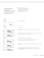
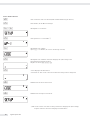
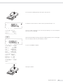
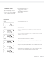
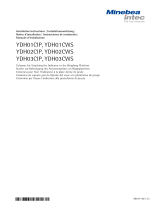
Example
External calibration and manual adjustment with default weights
Settings in the Setup menu:
1.9.1; 1.10.2
( Unload and zero the scale
� Start calibration; e.g., when calibration prompt (W) is flashing
c.ext.def
The “Calibration: External, default weights” menu item is displayed for 2 seconds...
...after which you are prompted to place the required weight on the platform (e.g., 10 kg)

18 Signum Option A15 Signum Option A15 19
Position the calibration weight on the weighing platform
The difference between the weight value and the true mass is displayed, with +/– sign.
External calibration The calibration record is printed, if adjustment was not performed and the process
Nom + 10000 g was stopped by pressing (
Diff. - 2 g
--------------------
) Activate calibration/adjustment manually (press the ( key to cancel)
The calibration weight is displayed at the conclusion of calibration
-------------------- A GMP-compliant printout is generated
14.01.2016 13:00
Model SIWR
Ser.no. 12345678
Type SIGNUM ADC
Ser.no. 12345678
Vers. 1.1007.12.1
BVers. 01-25-01
--------------------
External calibration
Nom. + 10000 g
Diff. - 2 g
External adjustment
Diff. + 0 g
--------------------
14.01.2016 13:02
Name:
--------------------
Unload the weighing instrument

20 Signum Option A15 Signum Option A15 21
Setting the Preload
Notes on Settings
! The preload can be set only when the
menu access switch is open.
– The “set preload” function must
be assigned to the � key (menu item
1.9.8) (see page 15).
! After setting the preload, close the
menu access switch and reset the
� key to its previous function
(e.g., external calibration/adjustment
with user-defined weights) under menu
item 1.9.
Clearing the Preload
Notes on Settings
! The preload can be cleared only when
the menu access switch is open.
– The “clear preload” function must
be assigned to the � key (menu item
1.9.9) (see page 15).
! After clearing the preload, close
the menu access switch and reset the
� key to its previous function
(e.g., external calibration/adjustment
with user-defined weights) under menu
item 1.9.
Calibration/Adjustment
without Weights
You can perform calibration/adjustment
without weights in the service mode
by entering the load cell specifications
(e.g., hopper weighing with known load
call specifications).
Notes on Settings
! Calibration/adjustment without
weights is not permitted on weighing
instruments used in legal metrology.
– Calibration/adjustment without weights
can only be performed in service mode,
and only when the menu access switch
is open.
– To enter the parameters required for
calibration/adjustment without weights,
activate the service mode (see “Service
Mode”), open the Setup menu and
select the COMSPEC submenu. Settings
are configured in the corresponding
numeric menu under menu item 1.19.
– The nominal capacity must be entered
in the weight unit selected under 1.7.x.
– Enter the sensitivity of the load cell
in mV/V (usually listed in the load cell
specification sheets).
– Note:
Select menu item 1.19.8 to store the
data entered. Once the ADC configura-
tion data has been stored, these param-
eters can no longer be read out.
Procedure
– Open the menu access switch
– Activate the service mode
– Select the weighing platform
– Enter the nominal capacity of the load
cell(s) under menu item 1.19.1. If the
weighing instrument has more than one
load cell, multiply the nominal capacity
accordingly (e.g., 4 load cells with 50 kg
nominal capacity each yields a nominal
capacity of 200 kg).
– Enter the sensitivity of the load cell in
mV/V under menu item 1.19.3.
– If the weighing instrument has multiple
load cells, enter the individual values
for the load cells under 1.19.3 through
1.19.6, or enter the mean value of all
load cells under 1.19.3.
– Enter the dead load (preload) for
a hopper in mV/V under 1.19.7.
– Save the values entered for calibration/
adjustment without weights by select-
ing menu item 1.19.8.
– Close the menu access switch
Diagram of Menu for Calibration/Adjustment Without Weights
1.19 Calibration/Adjustment without Weights (Entering Load Cell Specifications)
1.19.1 Nominal capacity
1.19.3 Sensitivity in mV/V for load cell 1 (or mean derived from all load cells)
119.4 Sensitivity in mV/V for load cell 2
1.19.5 Sensitivity in mV/V for load cell 3
1.19.6 Sensitivity in mV/V for load cell 4
1.19.7 Dead load (zero point offset)
1.19.8 Store values entered for 1.19
La page est en cours de chargement...
La page est en cours de chargement...
La page est en cours de chargement...
La page est en cours de chargement...
La page est en cours de chargement...
La page est en cours de chargement...
La page est en cours de chargement...
La page est en cours de chargement...
La page est en cours de chargement...
La page est en cours de chargement...
La page est en cours de chargement...
La page est en cours de chargement...
La page est en cours de chargement...
La page est en cours de chargement...
La page est en cours de chargement...
La page est en cours de chargement...
La page est en cours de chargement...
La page est en cours de chargement...
La page est en cours de chargement...
La page est en cours de chargement...
La page est en cours de chargement...
La page est en cours de chargement...
La page est en cours de chargement...
La page est en cours de chargement...
La page est en cours de chargement...
La page est en cours de chargement...
La page est en cours de chargement...
La page est en cours de chargement...
La page est en cours de chargement...
La page est en cours de chargement...
La page est en cours de chargement...
La page est en cours de chargement...
La page est en cours de chargement...
La page est en cours de chargement...
La page est en cours de chargement...
La page est en cours de chargement...
La page est en cours de chargement...
La page est en cours de chargement...
La page est en cours de chargement...
La page est en cours de chargement...
La page est en cours de chargement...
La page est en cours de chargement...
La page est en cours de chargement...
La page est en cours de chargement...
La page est en cours de chargement...
La page est en cours de chargement...
La page est en cours de chargement...
La page est en cours de chargement...
La page est en cours de chargement...
La page est en cours de chargement...
La page est en cours de chargement...
La page est en cours de chargement...
La page est en cours de chargement...
La page est en cours de chargement...
La page est en cours de chargement...
La page est en cours de chargement...
La page est en cours de chargement...
La page est en cours de chargement...
La page est en cours de chargement...
La page est en cours de chargement...
La page est en cours de chargement...
La page est en cours de chargement...
La page est en cours de chargement...
La page est en cours de chargement...
La page est en cours de chargement...
La page est en cours de chargement...
La page est en cours de chargement...
La page est en cours de chargement...
La page est en cours de chargement...
La page est en cours de chargement...
La page est en cours de chargement...
La page est en cours de chargement...
La page est en cours de chargement...
La page est en cours de chargement...
La page est en cours de chargement...
La page est en cours de chargement...
La page est en cours de chargement...
La page est en cours de chargement...
La page est en cours de chargement...
La page est en cours de chargement...
-
 1
1
-
 2
2
-
 3
3
-
 4
4
-
 5
5
-
 6
6
-
 7
7
-
 8
8
-
 9
9
-
 10
10
-
 11
11
-
 12
12
-
 13
13
-
 14
14
-
 15
15
-
 16
16
-
 17
17
-
 18
18
-
 19
19
-
 20
20
-
 21
21
-
 22
22
-
 23
23
-
 24
24
-
 25
25
-
 26
26
-
 27
27
-
 28
28
-
 29
29
-
 30
30
-
 31
31
-
 32
32
-
 33
33
-
 34
34
-
 35
35
-
 36
36
-
 37
37
-
 38
38
-
 39
39
-
 40
40
-
 41
41
-
 42
42
-
 43
43
-
 44
44
-
 45
45
-
 46
46
-
 47
47
-
 48
48
-
 49
49
-
 50
50
-
 51
51
-
 52
52
-
 53
53
-
 54
54
-
 55
55
-
 56
56
-
 57
57
-
 58
58
-
 59
59
-
 60
60
-
 61
61
-
 62
62
-
 63
63
-
 64
64
-
 65
65
-
 66
66
-
 67
67
-
 68
68
-
 69
69
-
 70
70
-
 71
71
-
 72
72
-
 73
73
-
 74
74
-
 75
75
-
 76
76
-
 77
77
-
 78
78
-
 79
79
-
 80
80
-
 81
81
-
 82
82
-
 83
83
-
 84
84
-
 85
85
-
 86
86
-
 87
87
-
 88
88
-
 89
89
-
 90
90
-
 91
91
-
 92
92
-
 93
93
-
 94
94
-
 95
95
-
 96
96
-
 97
97
-
 98
98
-
 99
99
-
 100
100


Minebea Intec Option A15. Analog/Digital Converter for Connecting a Reference Scale Le manuel du propriétaire
- Taper
- Le manuel du propriétaire
dans d''autres langues
Documents connexes
-
 Minebea Intec Miras 2 IW Models Le manuel du propriétaire
-
 Minebea Intec Signum 3 Ex Balances complètes SIWXS Le manuel du propriétaire
-
 Minebea Intec YDH02S display stand Le manuel du propriétaire
-
 Minebea Intec IS16EDE-H, IS16EDE-H0CE, IS34EDE-H, IS34EDE-H0CE, IS64EDE-H, IS64EDE-S, IS64EDE-H0CE Plate-forme de pesage Le manuel du propriétaire
-
 Minebea Intec Combics CAIXS2 antidéflagrant pour l’utilisation dans des atmosphères explosibles Le manuel du propriétaire
-
 Minebea Intec Midrics MIS1 | MIS2 Indicateurs Le manuel du propriétaire
-
 Minebea Intec Signum®3 SIWXSBBP | SIWXSBBS | SIWXSDCP | SIWXSDCS Balances complètes Le manuel du propriétaire
-
 Minebea Intec Columns for Attaching the Indicator to the Weighing Platform Le manuel du propriétaire


Autres documents
-
Brecknell SBI 110 Manuel utilisateur
-
Adam Equipment GBK 120 Manuel utilisateur
-
-
-
Baxtran SCU Manuel utilisateur
-
Ohaus cd-11 Manuel utilisateur
-
-
 Sentera Controls EVS-1-15-DM Mounting Instruction
-
 Sentera Controls MVSS1100CDM Mounting Instruction
-
KERN TFKB 65K-4-B Mode d'emploi

