SBC PCD2/3.W380 Le manuel du propriétaire
- Taper
- Le manuel du propriétaire

Document 27/632; Version EN06 │ 2015-03-04
User Manual
PCD2/3.W380
User Manual

Saia-Burgess Controls AG Table of contents
Document revisions
Manual PCD2/3.W380 │ Document 27/632; Version EN06 │ 2015-03-04 1
0 Table of contents
0 Table of contents ................................................................................................. 1
0.1 Document revisions ............................................................................................... 2
1 PCD2/3.W380, 8 analog configurable inputs ...................................................... 3
1.1 Module overview .................................................................................................... 3
1.2 Inputs connection ................................................................................................... 3
1.3 Specifications ........................................................................................................ 4
1.3.1 General data .......................................................................................................... 4
1.3.2 Technical data of inputs ......................................................................................... 5
1.4 Input wiring ............................................................................................................ 6
1.5 Input values acquisition .......................................................................................... 8
1.6 Configurable digital filters ....................................................................................... 8
1.7 Out of range indication ........................................................................................... 8
1.8 Input protections .................................................................................................... 9
1.9 Protection mode..................................................................................................... 9
1.10 LED signalization ................................................................................................. 10
1.11 Bloc diagram ........................................................................................................ 10
2 Preparing the PLC system ................................................................................ 11
3 Module in PG5 environment .............................................................................. 11
3.1 Preparing PG5 ..................................................................................................... 11
3.2 Choosing the module ........................................................................................... 11
3.3 Inputs configuration ............................................................................................. 12
3.4 Data acquisition ................................................................................................... 13
3.4.1 With media mapping ............................................................................................ 13
3.4.1.1 Inputs values ....................................................................................................... 13
3.4.1.2 Status and errors ................................................................................................. 13
3.4.1.2.1 Module Errors ...................................................................................................................... 14
3.4.1.2.2 Out Of Range ....................................................................................................................... 15
3.4.2 With direct access ................................................................................................ 16
4 Example of linearization .................................................................................... 17
5 Table of figures .................................................................................................. 18
6 Contact ............................................................................................................... 19

Saia-Burgess Controls AG Table of contents
Document revisions
Manual PCD2/3.W380 │ Document 27/632; Version EN06 │ 2015-03-04 2
0.1 Document revisions
Revision
Modified
Published
Comments
EN06
2015-03-04
2015-03-04
Text replacement: version ‘B’ replaced
by version ‘A2’.
EN05
2014-11-11
2014-11-11
Modifications of the RC filter value in
chapter Input Wiring.
Chapter deleted about active
protections for diode and resistance
measurements.
Auto reconfiguration feature added in
chapter “Protection mode”.
Modification of table 1, “Technical data”.
Over current limit modified to +/-30mA.
EN04
2014-08-20
2014-08-20
Modifications in chapters 1.1, 1.2, 1.3.1
and 1.4 about protective ground
connection.
EN03
2014-06-13
2014-06-13
Modifications in chapter 1.7 about input
protections.
EN02
2014-04-24
2014-04-24
Global update of the document
EN01
2013-09-27
2013-09-27
New document

Saia-Burgess Controls AG PCD2/3.W380, 8 analog configurable inputs
Module overview
Manual PCD2/3.W380 │ Document 27/632; Version EN06 │ 2015-03-04 3
1 PCD2/3.W380, 8 analog configurable inputs
This new module is a universal analog input module with improved embedded
features. This is an intelligent module with a very comfortable utilization. It is able
to measure voltages, currents, resistances and temperatures with the common
sensors available in the market and with a precision of 0.3% or better (based on
the full range). The inputs can be easily configured directly with PG5 and the
Device Configurator. Every channel can be configured individually.
This module can be used in applications where the data acquisition speed is
important. Each channel value is updated in internal buffer each 680us that means
each input value is refreshed at 1.5 kHz.
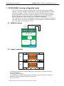
1.1 Module overview
I/O BUS
Inputs protections and
configurable switches
FPGA
Power
X1
Input channels
4 to 7
3 750 621
ADC
X0
Input channels
0 to 3
4
LED ERROR
PGND: 1mm2, length max. 20cm
PGND
Figure 1: Module overview
1.2 Inputs connection
X0
1: GND
3: GND
5: GND
7: GND
9: GND
0: CH0
2: CH1
4: CH2
6: CH3
8: GND
X1
1: GND
3: GND
5: GND
7: GND
9: GND
0: CH4
2: CH5
4: CH6
6: CH7
8: GND
Figure 2: Inputs connections
- 2 connections per channel (signal and ground). All the ground pins are internally
connected together.
- 4 channels per connector.
- In supplement, 2 ground connections per connector (pins 8 and 9). One of this pin
should be used for a protective ground connection.
- Wires up to 1mm
2
.

Saia-Burgess Controls AG PCD2/3.W380, 8 analog configurable inputs
Specifications
Manual PCD2/3.W380 │ Document 27/632; Version EN06 │ 2015-03-04 4
1.3 Specifications
1.3.1 General data
Technical data
COMPATIBILITY
PCD1, PCD2, PCD3
POWER
Module power supply voltage
+5V and V+ IOBUS
Current consumption
25mA on +5V and 25mA on V+
Galvanic separation
No
INPUTS
Number of inputs
8
Input ranges of each mode
Voltage -10V … +10V
Current -20mA … +20mA
Resistance 0Ω … 2’500Ω
0Ω … 300kΩ
Diode 0V … 5V
Pt1000 -50°C … +400°C
Ni1000 -50°C … +200°C
Ni1000L&S -30°C … +130°C
NTC10k used in range 0 … 300kΩ
NTC20k used in range 0 … 300kΩ
Absolute maximum input voltage
+/- 20V (independent of the inputs configuration)
Temperature error (0°C .. +55°C)
+/- 0.2%
Inputs configuration
Each input can be configured individually in 5 modes
(ranges above)
Configuration method
Software (PG5, Device Configurator)
User connector
Per channel: 1 pin for input and 1 pin for ground.
2 pins for protective ground and 2 pins for ground in
supplement.
Inputs wiring
Up to 1mm2
TIMING
Refresh of each channel
680us (all channels are updated during this time)
Hardware input filter time constant
Voltage τ = 2.5ms
Current τ = 2.5ms
Resistance ( < 2’500Ω)
1
τ < 4.4ms
(typ. for R<300kΩ)
2
τ ≈ 8ms
Diode (typ. for U<5V) τ ≈ 4.4ms
Digital input filter available
No Filter One value per cycle τ = 680 us
Filter 1: Mean of 4 cycles τ = 2.72 ms
Filter 2: Mean of 8 cycles τ = 5.44 ms
Filter 3
3
: Mean of 16 cycles τ = 10.88 ms
Min. number of I/O Bus accesses to read one
channel
28 (~28us)
Table 1: Technical data of the module
1
Temperature sensors Pt1000, Ni1000 and Ni1000L&S
2
Temperature sensors NTC10k and NTC20k.
3
Recommended filter, configured by default in Device Configurator

Saia-Burgess Controls AG PCD2/3.W380, 8 analog configurable inputs
Specifications
Manual PCD2/3.W380 │ Document 27/632; Version EN06 │ 2015-03-04 5
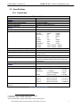
1.3.2 Technical data of inputs
Each input can be configured to be used in the following modes:
Mode
Resolution
[Bit]
Resolution
[measure]
Accuracy
(@ T
Ambient
= 25°C)
Display
Voltage
-10V ... +10V
12 + Sign
2.44 mV (linear)
R
IN
= 330kΩ
0.2% of measured value +/- 10mV
-10‘000…+10‘000
Current
-20mA…+20mA
12 + Sign
5.39 uA (linear)
R
SHUNT
= 225Ω
0.2% of measured value +/- 20uA
-20‘000…+20‘000
Resistance
0...2'500 Ω
12 bit
0.50... 0.80 Ω
Measuring current: 1.0 .. 1.3 mA
0.2% of measured value +/- 3 Ω
0...25’000
Resistance
0...300 kΩ
13 bit
0...10kΩ: 1...10 Ω
10k...40kΩ: 10..40 Ω
40k...70kΩ: 40..100 Ω
70k...100kΩ: 100...200 Ω
100k...300kΩ: 0.2...1.5 kΩ
Measuring current: 30µA..1.3 mA
0.2% of measured value +/- 40 Ω
0.2% of measured value +/- 160 Ω
0.5% of measured value +/- 400 Ω
1.0% of measured value +/- 800 Ω
2.5% of measured value +/- 5.0kΩ
0..300’000
Pt 1000
12 bit
-50...+400°C: 0.15 ... 0.25°C
Measuring current: 1.0 .. 1.3 mA
0.2% of measured value +/- 0.5°C
-500...4000
Ni 1000
12 bit
-50 ... +200°C: 0.09 ... 0.11°C
Measuring current: 1.0 .. 1.3 mA
0.2% of measured value +/- 0.5°C
-500...2000
Ni 1000 L&S
12 bit
-30 ... +130°C: 0.12 ... 0.15°C
Measuring current: 1.0 .. 1.3 mA
0.2% of measured value +/- 0.5°C
-300...1300
Diode
0...5’000mV
12 bit
1.22mV (linear)
Measuring current: 0.7...1.3mA
0.2% of measured value +/- 10mV
0…5’000
Table 2: Inputs specifications for each mode
The measuring current was chosen to be the best compromise between the
resolution and the sensors self-heating effect, which is negligible for most of the
sensors and applications. Even in bad measuring conditions with Pt/Ni1000
sensors with a low thermal coupling as 4mW/K, the maximal error produced by the
sensors self-heating is lower than 0.3°C.
The module offers the possibility to use NTC temperature sensors. The
corresponding input must be configured in mode “Resistance 0…300kΩ”.
Mode
Resistance
0…300kΩ
Resolution
[Bit]
Resolution
[measure]
Accuracy
(@ T
Ambient
= 25°C)
Display
NTC10k
1
13 bit
-40..+120°C: 0.05 ... 0.1°C
-20..+60°C: +/- 0.6°C
-30...+80°C: +/- 1.0°C
-40..+120°C: +/-2.8°C
-400...1200
2
NTC20k
3
13 bit
-10...+80°C: 0.02...0.05°C
-20...+150°C: < 0.15°C
-15...+75°C: +/- 0.6°C
-20...+95°C: +/- 1.0°C
+95..+120°C: +/-2.5°C
+120...+150°C: +/-5.8°C
-200...1500
4
Table 3: Inputs specifications for NTC10k and NTC20k
For an example of the utilization of a NTC sensor, please see the chapter 4
“Example of linearization”.
1
The temperature curves for the NTC10k are not standardized and may be different for each manufacturer. For this reason, the curves can
be loaded by the user program using the linearization FBox. The curve of the NTC10k from Produal is available in a CSV file and can be
downloaded from the Support Website.
2
This is the output value of the FBox for linearization. The module gives a resistance 0 … 300’000Ω.
3
For the same reason of NTC10k, the curve of the NTC20k from Honeywell can be downloaded from the Support Website.
4
This is the output value of the FBox for linearization. The module gives a resistance 0 … 300’000Ω.

Saia-Burgess Controls AG PCD2/3.W380, 8 analog configurable inputs
Input wiring
Manual PCD2/3.W380 │ Document 27/632; Version EN06 │ 2015-03-04 6
With an input configured in “Diode 0…5000mV”, it is possible to use integrated
circuit temperature sensors operating as a 2-terminal zener. A typical sensor for
this measurement is the LM235 for example.
Mode
Resistance
0…2500Ω
Resolution
[Bit]
Resolution
[measure]
Accuracy
(@ T
Ambient
= 25°C)
Display
LM235
12 bit
-40..+125°C: 0.12°C
0.2% of measured value +/- 1.0°C
-400...1250
1
Table 4: Inputs specifications for LM235
For an example of the utilization of a LM235 sensor, please see the chapter 4
“Example of linearization”.
1.4 Input wiring
The module is connected with the PCD by the I/O Bus connector. It can be
plugged with all the PCD versions PCD1, PCD2, PCD3. The module is completely
powered from the PCD bus, no external power supply is needed.
The inputs are connected with the module by two 10-pins connectors for cables up
to 1mm
2
. These connectors are very reliable and providing 2 pins per channel, one
for the input and the other connected to the ground. In each connector, 2 pins are
connected to the ground and can be used by user. In each connector, one of these
pins should be used as protective ground connection to avoid immunity problems
against external perturbations. A wire with a section of 1mm
2
and a maximum
length of 20cm is recommended for a good PGND connection.
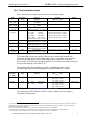
Every measurement mode has an equivalent input stage.
For resistance measurements (temperature sensors), 10V are provided through a
7.5kΩ resistor to the input.
7k5
4k7
330k
10V
TEMP.
SENSOR
220n
ADC
INPUT
Figure 3: Equivalent schematic of input in temperature and resistance mode
1
This is the output value of the FBox for linearization. The module gives a voltage 0 … 5’000mV.

Saia-Burgess Controls AG PCD2/3.W380, 8 analog configurable inputs
Input wiring
Manual PCD2/3.W380 │ Document 27/632; Version EN06 │ 2015-03-04 7
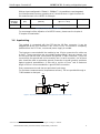
For current measurements, a shunt of 225Ω is connected to the ground.
330k
INPUT
225
4k7
220n
ADC
Figure 4: Equivalent schematic of input in "current" mode
In voltage measurements, the input is “directly” connected to the ADC.
330k
INPUT
4k7
220n
ADC
Figure 5: Equivalent schematic of input in "voltage" mode
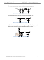
In “Diode” mode, the module measures voltages in an “active” way. The schematic
is the same as the mode for resistance measurements. The output values are
given in [mV]. This mode is useful for temperature sensors as LM235.
7k5
4k7
330k
10V
DIODE
(temp.
Sensor)
220n
ADC
INPUT
Figure 6: Equivalent schematic of input in "diode" mode

Saia-Burgess Controls AG PCD2/3.W380, 8 analog configurable inputs
Input values acquisition
Manual PCD2/3.W380 │ Document 27/632; Version EN06 │ 2015-03-04 8
1.5 Input values acquisition
The module is able to acquire and convert the each channel one by one, with a
total cycle time of 680µs:
CH0 à CH1 à CH2 à CH3 à CH4 à CH5 à CH6 à CH7 à CH0 à ...
680 us
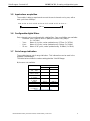
1.6 Configurable digital filters
Each channel can be configured with a digital filter. Four possibilities are available:
- Disabled: Each channel value is updated in buffer every 680µs
(f = 1.47kHz)
- 3 ms: Mean of 4 cycles, value updated every 2.72ms (f = 367Hz)
- 6 ms: Mean of 8 cycles, value updated every 5.44ms (f = 184Hz)
- 12 ms: Mean of 16 cycles, value updated every 10.88ms (f = 92Hz)
1.7 Out of range indication
The module has an out of range indication. This information can be read in the
registers “OutOfRange”.
The table below shows the values setting the bits “Out Of Range.
N/A means not available.
Mode
Out of range bit set…
Limit min
Limit max
Voltage
-10V ... +10V
N/A
N/A
Current
-20mA…+20mA
-20’002 uA
+20’002uA
Resistance
0...2'500 Ω
N/A
2518.7Ω
Resistance
0...300 kΩ
N/A
302’010Ω
Pt 1000
-50.0°C
+408.7°C
Ni 1000
-50.0°C
+210.3°C
Ni 1000 L&S
-30.0°C
+130°C
Diode
0...5’000mV
N/A
4’999 mV
Table 5: Limits for Out Of Range

Saia-Burgess Controls AG PCD2/3.W380, 8 analog configurable inputs
Input protections
Manual PCD2/3.W380 │ Document 27/632; Version EN06 │ 2015-03-04 9
1.8 Input protections
The design supports an input voltage between -20V to +20V in all the modes of
measurement. It can be considered a passive protection. Higher values can
damage the module. For voltages higher than +/-13V a current passes through the
circuit. It can be calculated approximately: I
overvoltage
= (V
in
– 13V) / 225Ω.
In this situation, the values measured on the other channels can be falsified.
Active protections are implemented for current measurements, but in all conditions
the input voltage must be lower than +/-20V. The bit corresponding to the channel
is set to ‘1’ in the register “ModuleErrors” when the protection is enabled.
If current mode is chosen the measuring shunt
is connected to ground through the switch as
shown in the picture on the left.
In case the current is higher than 30mA
1
the
switch opens to protect the measuring shunt.
For voltage lower than +/-13V on the opened
input the current will be kept lower than 1mA. If
the voltage on the opened input rises above +/-
13V the current can be approximately
calculated using the formula:
I
overvoltage
= (V
in
– 13V) / 225Ω
Care should be taken to keep input voltage
below +/-20V.
1.9 Protection mode
The input stage configuration (switch) is automatically modified when the module
enters in protection mode. The input values of the others channels could be out of
the specified tolerances when a channel is in protection mode.
The modules from version ‘A2’ have an automatic reconfiguration mechanism after
the active protection has become active. Once triggered, the input will remain for
10 seconds in protection mode. After 10 seconds, the input will switch back to
normal operating configuration. If the input is still in overload condition, protection
will again be activated. This feature is available only with firmware version greater
than 1.24.10.
For Modules with version ‘A’ or ‘A1’ the protection will also be activated when an
overload occurs, but to switch back to normal operation mode the PCD has to be
restarted.
1
HW version ‘A’ and ‘A1’ : Limit = +/-24mA
INPUT
I > 30mA
225
Vz = 13V
Sw
opened
INPUT
I < 30mA
225
Sw
closed

Saia-Burgess Controls AG PCD2/3.W380, 8 analog configurable inputs
LED signalization
Manual PCD2/3.W380 │ Document 27/632; Version EN06 │ 2015-03-04 10
1.10 LED signalization
One red LED is placed near the channel 0. The LED is enabled when an error
occurs on the module. This is a general indication and the details of the error must
be read in the specific register of the module.
The signaled errors are:
- Configuration error: The desired inputs configuration is not applied correctly.
- ADC error: A/D converter doesn’t respond.
- Calibration error: Module not calibrated.
- Protection mode: An input channel has been automatically put in protection
mode, because the module detects a situation which can
cause important damages to hardware.
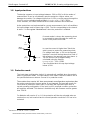
1.11 Bloc diagram
The PLC communicates with the module through the I/O Bus.
The data acquisition is independent of the rest. The input values are continuously
updated into the internal buffer. One value is stored per channel. The values are
sent to the PLC when the user program sends a defined request to the module.
EEPROM
FPGA
Buffer
PLC
A
D
Input
Config
SW
Input
CH0 to
CH3
Input
CH4 to
CH7
All channels are converted in
continuous, independently of
user program.
User program has access to the
buffer for reading input converted
values, but it has no access directly
to hardware.
I/O BUS
MODULE
Figure 7: Global diagram of module structure conception
The configuration of the module is done in PG5 Device Configurator. The user
program can read the input values or input configurations by specific registers.

Saia-Burgess Controls AG Preparing the PLC system
Preparing PG5
Manual PCD2/3.W380 │ Document 27/632; Version EN06 │ 2015-03-04 11
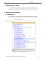
2 Preparing the PLC system
The PCD used for the module PCDx.W380 must be updated with a firmware
version 1.22.28 or higher. Please, download the last firmware version from the
support website and load it in the PCD with the PG5 Firmware Downloader Tool.
3 Module in PG5 environment
3.1 Preparing PG5
This module can only be used with the software version PG5 2.1.300 or higher.
Please, verify if your system is up-to-date. You find the last PG5 version on the
support Website www.sbc-controls.com.
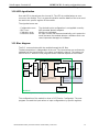
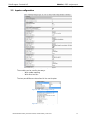
3.2 Choosing the module
Figure 8: List of modules in PG5

Saia-Burgess Controls AG Module in PG5 environment
Inputs configuration
Manual PCD2/3.W380 │ Document 27/632; Version EN06 │ 2015-03-04 12
3.3 Inputs configuration
Figure 9: PG5, inputs configuration (1)
The module can be used by two ways:
- With media mapping
- With direct access
The two possibilities are described in the next chapter.
Figure 10: PG5, inputs configuration (2)
Figure 11: PG5, inputs configuration (3)

Saia-Burgess Controls AG Module in PG5 environment
Data acquisition
Manual PCD2/3.W380 │ Document 27/632; Version EN06 │ 2015-03-04 13
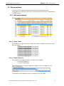
3.4 Data acquisition
The format of the values is directly linked with the corresponding input
configuration. For example, the value is a temperature if the input is configured for
a Ni1000 sensor.
3.4.1 With media mapping
With the media mapping enabled, each module has these following registers:
Figure 12: PG5, media mapping
3.4.1.1 Inputs values
In a Fupla or IL program, the input values are saved in registers and can be read
with the names:
- IO.Slot0.AnalogueInput0 for channel 0
- IO.Slot0.AnalogueInput1 for channel 1
- IO.Slot0.AnalogueInput2 for channel 2
- IO.Slot0.AnalogueInput3 for channel 3
- IO.Slot0.AnalogueInput4 for channel 4
- IO.Slot0.AnalogueInput5 for channel 5
- IO.Slot0.AnalogueInput6 for channel 6
- IO.Slot0.AnalogueInput7 for channel 7
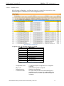
3.4.1.2 Status and errors
Two registers are implemented for the status of the module:
- IO.Slot0.ModuleErrors
- IO.Slot0.OutOfRange
This information can be read as registers or flags. It can be configured in the
device configurator:
Figure 13: Media type for diagnostic
The behavior of the diagnostic bits is the same for the two types.

Saia-Burgess Controls AG Module in PG5 environment
Data acquisition
Manual PCD2/3.W380 │ Document 27/632; Version EN06 │ 2015-03-04 14
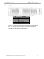
3.4.1.2.1 Module Errors
With flag type configuration, one flag per channel is created for the protection state
and three flags for Calibration, ADC and Configuration errors.
Figure 14: Flags for module errors
In register type, the following register is created:
Bit
Description
11 .. 15
Reserved
10
Configuration error
9
ADC error
8
Calibration error
7
CH7 protection
6
CH6 protection
5
CH5 protection
4
CH4 protection
3
CH3 protection
2
CH2 protection
1
CH1 protection
0
CH0 protection
Table 6: Description of ModuleErrors register
- Configuration error: The desired inputs configuration is not applied
correctly.
- ADC error: A/D converter doesn’t respond.
- Calibration error: Module not calibrated.
- Protection mode: An input channel has been automatically put in
protection mode, because the module detects a
situation which can cause important damages to
hardware.

Saia-Burgess Controls AG Module in PG5 environment
Data acquisition
Manual PCD2/3.W380 │ Document 27/632; Version EN06 │ 2015-03-04 15
3.4.1.2.2 Out Of Range
One flag per channel is created to signalize when the input values are out of
range:
If the configuration is done in “register type”, an 8-bit register is created:
Bit
Description
7
CH7 out of range
6
CH6 out of range
5
CH5 out of range
4
CH4 out of range
3
CH3 out of range
2
CH2 out of range
1
CH1 out of range
0
CH0 out of range
Table 7: Description of OutOfRange register
The “out of range” status bit means that the converted value is out of the specified
range. The input value stay at the minimum or other maximum value allowed.
The mode “VOLTAGE” hasn’t out of range detection.

Saia-Burgess Controls AG Module in PG5 environment
Data acquisition
Manual PCD2/3.W380 │ Document 27/632; Version EN06 │ 2015-03-04 16
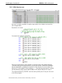
3.4.2 With direct access
The module allows direct access with RDP commands.
Here an IL program example to read the input values, the module errors and the
out of range status:
Declaration of a mask:
Commands for reading module data:
The type of read data for each “register” is the same than using media mapping.
The mask after the command RDPB is only for the comfort. The RDPB command
has an integrated 2-complement conversion. If the channel 7 is out of range, the
bits 8 to 31 of the register R 9 are setting to ‘1’. To avoid this phenomenon, a mask
can be placed to keep only the desired data on R 9 and the bits 8 to 31 stay ‘0’.
The register MODULE_ERRORS must be read cyclically even if they are not used
in the user program.

Saia-Burgess Controls AG Example of linearization
Data acquisition
Manual PCD2/3.W380 │ Document 27/632; Version EN06 │ 2015-03-04 17
4 Example of linearization
The choice of NTC sensors is not available in the Device Configurator because
these sensors are not standardized. To use a NTC with the module
PCD2/3.W380, please configure the desired channel in mode “0..300kΩ” and use
the linearization FBox available in PG5 environment.
This FBox can be used to enter the own tables for the conversion of a resistance
value in a temperature value.
A project example can be downloaded from the SBC Support Website at this
location:
http://www.sbc-support.com
This project example can be used for temperature measurements with integrated
circuits operating as a 2-terminal zener too. This FBox can be used to enter the
own tables for the conversion of a voltage value in a temperature value.
The desired channel must be configured in mode “Diode 0...5000mV”.

Saia-Burgess Controls AG Table of figures
Data acquisition
Manual PCD2/3.W380 │ Document 27/632; Version EN06 │ 2015-03-04 18
5 Table of figures
Figure 1: Module overview ........................................................................................................................................ 3
Figure 2: Inputs connections ...................................................................................................................................... 3
Figure 3: Equivalent schematic of input in temperature and resistance mode ......................................................... 6
Figure 4: Equivalent schematic of input in "current" mode ....................................................................................... 7
Figure 5: Equivalent schematic of input in "voltage" mode ....................................................................................... 7
Figure 6: Equivalent schematic of input in "diode" mode .......................................................................................... 7
Figure 7: Global diagram of module structure conception ...................................................................................... 10
Figure 8: List of modules in PG5 ............................................................................................................................... 11
Figure 9: PG5, inputs configuration (1) .................................................................................................................... 12
Figure 10: PG5, inputs configuration (2) .................................................................................................................. 12
Figure 11: PG5, inputs configuration (3) .................................................................................................................. 12
Figure 12: PG5, media mapping .............................................................................................................................. 13
Figure 13: Media type for diagnostic ....................................................................................................................... 13
Figure 14: Flags for module errors ........................................................................................................................... 14
Table 1: Technical data of the module ....................................................................................................................... 4
Table 2: Inputs specifications for each mode ............................................................................................................. 5
Table 3: Inputs specifications for NTC10k and NTC20k .............................................................................................. 5
Table 4: Inputs specifications for LM235 ................................................................................................................... 6
Table 5: Limits for Out Of Range ................................................................................................................................ 8
Table 6: Description of ModuleErrors register ......................................................................................................... 14
Table 7: Description of OutOfRange register ........................................................................................................... 15

Saia-Burgess Controls AG Contact
Data acquisition
Manual PCD2/3.W380 │ Document 27/632; Version EN06 │ 2015-03-04 19
6 Contact
Saia-Burgess Controls AG
Bahnhofstrasse 18
CH-3280 Murten / Switzerland
Telephon: ................................. +41 26 672 72 72
Fax: ......................................... +41 26 672 74 99
E-Mail Support: ........................ support@saia-pcd.com
Supportseite: ........................... www.sbc-support.com
SBC Seite: ............................... www.saia-pcd.com
Internationale Vertretungen &
SBC Verkaufsgesellschaften: ... www.saia-pcd.com/contact
-
 1
1
-
 2
2
-
 3
3
-
 4
4
-
 5
5
-
 6
6
-
 7
7
-
 8
8
-
 9
9
-
 10
10
-
 11
11
-
 12
12
-
 13
13
-
 14
14
-
 15
15
-
 16
16
-
 17
17
-
 18
18
-
 19
19
-
 20
20


SBC PCD2/3.W380 Le manuel du propriétaire
- Taper
- Le manuel du propriétaire
dans d''autres langues
- English: SBC PCD2/3.W380 Owner's manual
Documents connexes
-
SBC PCD2/3.W380 Le manuel du propriétaire
-
-
-
-
SBC PCD2.H222 & PCD3.H222 stepper motor module Le manuel du propriétaire
-
-
-
-
-