Power Fist 8509820 Le manuel du propriétaire
- Catégorie
- Groupes électrogènes
- Taper
- Le manuel du propriétaire

V 4.1 8509820
Please read and understand all instructions before use. Retain this manual for future reference.
User Manual
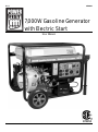
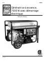
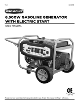
7,000W Gasoline Generator
with Electric Start

8509820 7,000W Gasoline Generator with Electric Start V 4.1
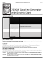
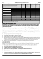
SPECIFICATIONS
INTRODUCTION
This 4 stroke, air cooled, OHV gas unit is easy to use. A portable gas generator means you will never have to be without
electricity in any emergency. A tire kit and battery are included.
SAFETY
WARNING! Read and understand all instructions before using this generator. The operator must follow basic
precautions to reduce the risk of personal injury and/or damage to the equipment.
Keep this manual for safety warnings, precautions, operating or inspection and maintenance instructions.
HAZARD DEFINITIONS
Please familiarize yourself with the hazard notices found in this manual. A notice is an alert that there is a possibility of
property damage, injury or death if certain instructions are not followed.
DANGER! This notice indicates an immediate and specific hazard that will result in severe personal injury or death if the
proper precautions are not taken.
WARNING! This notice indicates a specific hazard or unsafe practice that could result in severe personal injury or death if
the proper precautions are not taken.
Engine Engine Displacement 420 c.c.
Engine Type 4 Stroke OHV
Continuous Output 6,500 W
Maximum Output 7,000 W
Half Load Run Time 9 Hours
Spark Plug Gap 0.5 ~ 0.7 mm
Tank Capacity 6.6 Gal. (25 L)
Recommended Oil 4 Stroke Gasoline Oil SE, SF from API Service Class
OR
SAE 10W-30 Oil Equivalent to SG Class
Operating Noise
97 dB
Power Outlets 1 Twist-Locking (AC) 120/240V, 30A, 60 Hz
4 Standard (AC) 120V, 20A, 60 Hz
1 DC 12V
Features Fuel Type Gasoline
Air Cooled Yes
Electric Start Yes
Recoil Start Yes
Low Oil Shutdown Yes
Tire Size 8
7,000W Gasoline Generator
with Electric Start
2 For technical questions call 1-800-665-8685

V 4.1 7,000W Gasoline Generator with Electric Start 8509820
CAUTION! This notice indicates a potentially hazardous situation that may result in minor or moderate injury if proper
practices are not taken.
NOTICE! This notice indicates that a specific hazard or unsafe practice will result in equipment or property damage, but
not personal injury.
WORK AREA
1. Operate in a safe work environment. Keep your work area clean, well lit and free of distractions.
2. Only operate in well-ventilated areas.
3. Do not install or use in the presence of flammable gases or liquids.
4. Store the generator properly in a safe and dry location. Keep the generator out of the reach of children.
PERSONAL SAFETY
WARNING! Wear personal protective equipment approved by the Canadian Standards Association (CSA) or American
National Standards Institute (ANSI).
PERSONAL PROTECTIVE EQUIPMENT
1. Always wear impact safety goggles that provide front and side protection for the eyes. Eye protection equipment should
comply with CSA Z94.3-07 or ANSI Z87.1 standards based on the type of work performed.
2. Wear gloves that provide protection based on the work materials or to reduce the effects of tool vibration.
a. Do not wear gloves when operating a tool that can snag the material and pull the hand into the tool.
3. Wear protective clothing designed for the work environment and tool.
4. Non-skid footwear is recommended to maintain footing and balance in the work environment.
5. Wear steel toe footwear or steel toe caps to prevent a foot injury from falling objects.
6. This generator can cause hearing damage. Wear hearing protection gear with an appropriate Noise Reduction
Rating to withstand the decibel levels.
PERSONAL PRECAUTIONS
Control the generator, personal movement and the work environment to avoid personal injury or damage to the generator.
1. Do not operate the generator when tired or under the influence of drugs, alcohol or medications.
2. Avoid wearing clothes or jewelry that can become entangled with the moving parts of the generator. Keep long hair
covered or bound.
3. Do not overreach when operating the generator. Proper footing and balance enables better control in unexpected situations.
SPECIFIC SAFETY PRECAUTIONS
1. Use the correct generator for the job. This generator was designed for a specific function. Do not modify or alter
this generator or use it for an unintended purpose.
2. All users must understand the operation of all controls and learn how to stop the generator quickly in case
of emergency.
3. Do not tamper with governor spring, links or other engine parts to increase speed or power.
4. The engine and exhaust become very hot during operation. Severe thermal burns can occur on contact, especially
with the muffler.
a. Keep the generator at least 3 feet (1 meter) away from buildings and other equipment during operation.
b. Remove accumulated debris from muffler and cylinder area. Combustible debris, such as leaves, grass, brush,
etc. can catch fire if they come in contact with a hot engine.
c. Do not place anything on the generator while it is running.
d. Allow muffler, engine cylinder and fins to cool before touching.
5. The manufacturer of the equipment, on which this engine is installed, specifies the engine’s top speed during
operation. DO NOT exceed this speed.
Visit www.princessauto.com for more information 3

8509820 7,000W Gasoline Generator with Electric Start V 4.1
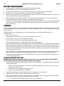
CARBON MONOXIDE POISONING
DANGER! Never operate a gas engine indoors or in a confined space as the exhaust contains carbon monoxide gas.
Inhalation of carbon monoxide gas can lead to illness or death. The area must be well ventilated. Opening windows
and doors is not enough to ventilate an area.
Carbon monoxide is a colourless and odourless gas that is difficult to detect. Carbon monoxide poisoning results from
inhalation of the gas and may be lethal if left untreated. Evacuate all people to an area with clean air and seek immediate
medical attention for any person experiencing the following symptoms:
1. Headache
2. Confusion
3. Shortness of Breath
4. Weakness
5. Chest Pain
6. Dizziness
7. Vision Trouble
8. Nausea and Vomiting
9. Unconsciousness
ELECTRICAL SAFETY
WARNING! To reduce risk of electric shock, be certain that the power cord is connected to a properly grounded
power outlet.
1. Protect yourself against electric shocks when working on electrical equipment. Avoid body contact with grounded
surfaces. There is an increased chance of electrical shock if your body is grounded.
2. Do not expose the generator to rain or wet conditions. Water entering the generator will increase the risk of electric shock.
3. Make certain the power source conforms to requirements of your equipment (see Specifications).
4. When wiring an electrically driven device, follow all electrical and safety codes, as well as the most recent Canadian
Electrical Code (CE) and Canadian Centre for Occupational Health and Safety (CCOHS).
WARNING! All wiring should be performed by a qualified electrician.
BATTERY SAFETY
WARNING! Do not charge a damaged or frozen battery. Contact your local municipality for proper disposal procedures.
WARNING! Only charge a battery with a charger designed for that purpose. Do not use modified chargers or a
charger that does not specify the voltage, amperage or recharge rate. Improper charging can lead to battery
rupturing.
EXPLOSIVE GASES
Lead-acid generates oxygen and hydrogen gas as part of their normal function. Hydrogen becomes explosive when
concentrations exceed 4.1 percent.
1. Remove any source of ignition such as an open flame or a device like a heater from the area. Sparks may also ignite
the gas.
2. Lead batteries contain sulfuric acid, also referred to as electrolyte or battery acid. The acid is corrosive and can
cause a skin burn if leaking or splashed. The acid may also pose a threat if inhaled or ingested accidentally. The
acid can destroy normal clothing and injure the flesh underneath. Wear splash-proof goggles and protective
clothing when handling a battery.
3. Even a discharged battery may still carry a charge. To prevent a shock, place battery terminal caps or covers over the
terminal to prevent accidental contact. Hold the battery by the bottom if moving the battery to a different location.
4. Batteries are heavy due to the weight of the lead and liquid contained inside. A lead-acid battery could weigh
upwards of 50-60 lbs. Use safe lifting methods if moving the battery.
UNPACKING
WARNING! Do not operate the generator if any part is missing. Replace the missing part before operating. Failure
to do so could result in a malfunction and personal injury.
Remove the parts and accessories from the packaging and inspect for damage. Make sure that all items in the parts list
are included.
Contents:
• 7,000W Gasoline Generator
4 For technical questions call 1-800-665-8685

V 4.1 7,000W Gasoline Generator with Electric Start 8509820
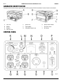
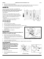
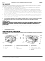
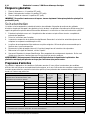
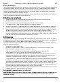
GENERATOR IDENTIFICATION
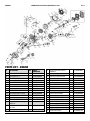
Compare the illustration with your generator to familiarize yourself with the location of various features and controls.
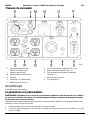
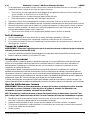
CONTROL PANEL
A Fuel Tank
B Muffler
C Dipstick
D Fuel Tank Cap
E Spark Plug
F Pipe Support
G Carburetor Choke Lever
H Recoil Starter Handle
I Fuel Valve Lever
J Air Cleaner
Fig.
1
Fig. 2
Visit www.princessauto.com for more information 5

8509820 7,000W Gasoline Generator with Electric Start V 4.1
K Starter Switch (ON/OFF/START)
L Power indicator
M Low Oil Indicator
N Voltmeter
O Breaker Bar (ON/OFF)
P DC Circuit Reset
Q 120V Standard Power Outlets (x 4)
R 120V AC Resent Buttons
S 120/240V AC Twist Lock Power Outlet
T Ground Terminal
U DC Power Outlet
ASSEMBLY
The generator comes preassembled.
PREPARING THE GENERATOR
WARNING! Do not start or run the generator in an enclosed area, even if doors or windows are open. Engine exhaust
contains carbon monoxide, an odourless and colourless poison gas.
The generator requires little preparation for use once out of the box. However, before attempting to start the generator,
be sure it is ready.
1. Inspect the generator and remove any packaging inside the frame.
2. Make sure spark plug (E), muffler (B), fuel cap (D) and air cleaner (J) are in place and secured.
3. Do not crank engine with spark plug removed. Ensure spark plug lead is securely connected to spark plug,
otherwise unintentional sparking can result, causing fire or electric shock.
4. Place the generator on a flat surface. Check the oil level (see How to Check Oil).
5. Fill the fuel tank with gasoline (see How to Add Fuel). Do not start the engine until any spilled fuel has evaporated.
OPERATION
PRE-OPERATION CHECKS
NOTICE! The generator is not shipped with oil. Before starting the engine, add oil according to the instructions in
this manual. Starting the engine without oil will damage the engine beyond repair.
Check the engine’s condition before operating to maximize the user’s safety and the service life of the engine. Ensure that
the generator is level and the engine switch is in the OFF position before beginning the pre-operation checks.
GENERAL CONDITION
1. Look around and underneath the generator for signs of oil or gasoline leaks.
2. Remove any excessive dirt or debris, especially around the muffler (B) and recoil starter (H).
3. Look for signs of damage.
4. Check that all shields and covers are in place.
5. Check that all nuts, bolts and screws are tight.
CHECK THE ENGINE
1. Check the fuel level (see How to Add Fuel).
2. Check the engine oil level. Running the engine with a low oil level can cause engine damage (see How to
Check/Add Oil).
3. Check the air filter element. A dirty air filter will reduce engine performance (see How to Service the Air Filter).
GROUND THE GENERATOR
The generator must be properly grounded to prevent electric shocks. The generator is equipped with a ground terminal
connector. Attach a length of 10 AWG (minimum) wire to a ground rod driven into the earth. Attached the other end to
the ground terminal connector. Consult municipal electrical codes or a qualified electrician to confirm
grounding requirements.
6 For technical questions call 1-800-665-8685

V 4.1 7,000W Gasoline Generator with Electric Start 8509820
STARTING THE GENERATOR
ELECTRIC START
1. Remove all the loads from AC and DC power outlets and switch off the AC breaker.
2. Move the fuel valve lever (I) to the ON position. The fuel valve is located between the fuel tank and the carburetor.
When the valve lever is in the ON position, fuel is allowed to flow from the fuel tank to the carburetor.
3. Move the choke lever (G) to the CLOSED position. The choke is used to provide an enriched fuel mixture when
starting a cold engine. It can be opened and closed by operating the choke lever manually. The choke is usually
unnecessary when restarting a warm engine.
4. Turn the main generator Key (K) to the START position to start the engine.
5. The engine should turn over and start running. If engine floods, set the choke lever to the OPEN position, place the
throttle in FAST and attempt to restart.
6. If the choke lever was moved to the CLOSED position to start the engine, gradually move it to the OPEN position as
the engine warms up.
RECOIL START
WARNING! Failure to follow the steps below will result in rapid retraction of the starter cord faster than the user
can let go. This will pull the user’s hand and arm toward the engine, possibly resulting in serious injury.
The recoil start is available as a back-up method to start the generator without using the battery.
1. Remove all the loads from AC and DC power outlets and switch off the AC breaker.
2. Move the fuel valve lever (I) to the ON position. The fuel valve is located between the fuel tank and the carburetor.
When the valve lever is in the ON position, fuel is allowed to flow from the fuel tank to the carburetor.
3. Move the choke lever (G) to the CLOSED position. The choke is used to provide an enriched fuel mixture when
starting a cold engine. It can be opened and closed by operating the choke lever manually. The choke is usually
unnecessary when restarting a warm engine.
4. Turn the main generator key (K) to the ON position.
5. Pull Start
a. Pull the recoil starter handle (H) lightly until you feel resistance.
b. Pull the recoil starter handle briskly as soon as resistance is felt.
c. Do not allow the recoil starter handle to snap back against the engine. Instead, return the starter grip gently by hand.
6. The engine should turn over and start running. If engine floods, set the choke lever to the OPEN position, place the
throttle in FAST and crank until engine starts.
7. If the choke lever was moved to the CLOSED position to start the engine, gradually move it to the OPEN position as
the engine warms up.
Occasionally you may hear a light ‘spark knock’ or ‘pinging’ (metallic rapping noise) while operating under heavy loads.
This is no cause for concern.
Should the spark knock or pinging continue to occur when the engine speed is steady under a normal load, consider
replacing the fuel. If the sounds continue after changing the fuel, contact Princess Auto Ltd. for a solution or see a
qualified technician.
NOTICE! Running the engine with persistent spark knock or pinging can cause engine damage.
RUNNING THE GENERATOR
1. Warm up the generator without load for 3 minutes.
2. Be sure that all appliances are in good working condition before connecting them to the generator.
3. Attach appliances, one at a time starting with the appliance with the highest current rating. Most appliance motors
require more than their rated wattage for start up. Do not exceed the current limit specified for any one socket. See
Wattage Reference Chart.
4. Turn off the generator immediately if an appliance becomes sluggish, stops suddenly or acts in an abnormal
manner. Disconnect and inspect the appliance.
Visit www.princessauto.com for more information 7

8509820 7,000W Gasoline Generator with Electric Start V 4.1
5. Reduce the electric load on the circuit if the circuit protector trips. Wait a few minutes before resuming operation.
6. If the voltmeter registers a voltage that is too high, stop the generator, disconnect all appliances and examine the
generator for the cause of the malfunction.
7. Do not attempt to run a DC and AC appliance at the same time.
8. The DC terminal may be used for charging 12-volt automatic-type batteries only. Disconnect the negative pole
battery cable from the battery when setting up to charge the battery. Do not reverse the charging cables. Serious
damage to the generator and/or battery may occur.
9. Ensure a skilled electrician connects the generator when incorporating the generator into a home power circuit. A
properly installed transfer switch is required. An improper connection can damage the house’s electrical system,
generator and any attached appliances or cause a fire.
TURN OFF THE GENERATOR
1. Switch the AC breaker to the OFF position.
2. Turn the engine switch to the OFF position.
3. Set fuel valve lever to the OFF position.
IMPORTANT! To stop the generator in an emergency, turn the main generator switch to the OFF position.
CARE & MAINTENANCE
The following section includes a maintenance schedule, routine inspection and simple maintenance procedures using
basic hand tools. Service tasks that are more difficult or require special tools are best handled by a technician or other
qualified mechanic.
1. Maintain the generator with care. A well-maintained generator is more efficient and less likely to have problems.
2. Follow instructions for servicing
3. Inspect the generator components periodically. Have damaged or worn components repaired or replaced by an
authorized technician.
4. Replacement parts must match the original. Use manufacturer recommended parts when possible.
5. Disconnect the spark plug lead and keep it away from the spark plug during maintenance and repairs.
a. Disconnect the negative battery lead, then the positive lead.
6. Maintain the generator’s label and name plate. These carry important information. If unreadable or missing, contact
Princess Auto Ltd. for replacements.
WARNING! Only qualified service personnel should repair the generator. An improperly repaired generator may
present a hazard to the user and/or others.
MAINTENANCE SCHEDULE
This schedule applies to normal operating conditions. If you operate your engine under severe conditions, such as sustained
high-load or high-temperature operation or use in unusually wet or dusty conditions, consult a qualified technician for
recommendations applicable to your individual needs and use.
8 For technical questions call 1-800-665-8685

V 4.1 7,000W Gasoline Generator with Electric Start 8509820
FUEL RECOMMENDATIONS
NOTICE! Do not use unapproved gasoline, such as E85. Do not mix oil in gasoline or modify the engine to run on
alternate fuels. This can damage the engine components. To protect the fuel system from gum formation, mix a
fuel stabilizer into the fuel.
This engine is certified to operate on unleaded gasoline with a minimum of 87 octane/87 AKI (91 RON). Use gasoline without
ethanol or similar alcohol based additives. Gasoline with up to 10% ethanol (gasohol) or up to 15% MTBE (methyl tertiary
butyl ether) may be used if required.
If the engine is routinely operated at altitudes over 5,000 ft (1,524 meters), it will be necessary to have a qualified technician
modify the engine for increased performance. Fuel should be a minimum of 85 octane/85 AKI (91 RON) to prevent decreased
performance.
1. Use only an approved fuel container for refueling the engine.
2. Store fuel out of direct sunlight in a cool and dry location.
3 Inspect container for fuel leaks. Replace any container that leaks.
4. You may occasionally hear a light spark knock or pinging (metallic rapping noise) while the engine is operating under heavy
loads. This is no cause for concern. If spark knock or pinging occurs at a steady engine speed under normal load, switch to
a premium gasoline or change brands of gasoline. If spark knock or pinging persists, see an authorized repair centre.
5. Never use stale or contaminated gasoline or an oil/gasoline mixture designed for two-stroke motors.
HOW TO ADD FUEL
DANGER! Fuel is very flammable. Use extreme care when handling or storing fuel. An ignition source contacting
the fumes or fuel may result in a fire or explosion and cause fatal or serious injuries to you or a bystander.
1. Refuel outdoors or in a well-ventilated area and immediately wipe up spills. Fuel can damage paint and plastic.
2. Stop the engine and position equipment on a level surface.
3. Let engine cool at least 2 minutes before removing the fuel cap.
4. Clean the fuel cap (D) area of dirt and debris. Do not allow dirt or water to enter the fuel tank.
5. Remove the fuel cap slowly to allow the pressure to equalize.
6. Check the fuel level.
7. Fill the tank to approximately 1.5 in. (38 mm) below the top of the fuel tank to allow for fuel expansion. Take care to not
overfill the tank. It may be necessary to lower the fuel level depending on operating conditions.
Regular Service Period *
Before
Each Use
First Month
or 20 Hours
Every 3
months or
50 Hours
Every 6
months or
100 Hours
Every Year
or 300
Hours
Performed at every indicated month or
operating hour interval, whichever comes
first.
Engine Oil Check X
Change X X
Air Cleaner Check X
Clean X **
Sediment Cup Clean X
Spark Plug Clean / Adjust X
Replace X
Idle Speed Check / Adjust X
Valve Clearance
Check / Adjust
X
Combustion Chamber Clean After every 500 Hours
Fuel Tank and Filter Clean X
Fuel Tube Check Every 2 years (replace if necessary)
* For commercial use, log hours of operation to determine proper maintenance intervals.
** Service more frequently when used in dusty areas.
Visit www.princessauto.com for more information 9

8509820 7,000W Gasoline Generator with Electric Start V 4.1
8. Reinsert the fuel tank cap and tighten.
9. Wipe up any spilled fuel before starting the engine or allow to evaporate. Spilled fuel is both a fire hazard and an
environmental hazard. Dispose of the fuel soaked rags in a proper hazardous waste container.
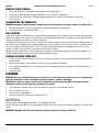
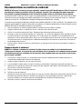
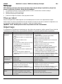
ENGINE OIL
High-quality detergent engine oils are acceptable if the
American Petroleum Institute (API) performance rating is SE,
SF, SG or higher. Always check the API service label on the
oil container for the performance rating. Do not use
special additives.
SAE 10W-30 is recommended for general use. Other
viscosities may be used when the average temperature in
your area is within the range indicated in the chart below.
*Below 4°C (40°F), the use of SAE 30 will result in
hard starting.
**Above 27°C (80°F), the use of 10W-30 may cause
increased oil consumption. Check oil level.
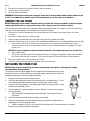
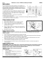
HOW TO CHECK OIL
1. Level the generator.
2. Clean the oil fill area of any debris.
3. Remove the dipstick (C) and wipe with a clean cloth.
4. Insert the dipstick into the filler neck and screw it in as shown in Fig. 4.
5. Remove the dipstick and check that the oil is between the
Full and Fill marks. Add or drain oil based on the
measurement.
6. Replace and tighten the dipstick.
HOW TO ADD OIL
IMPORTANT! Read the Engine Oil section before adding oil to
ensure that it is suitable for the engine.
1. Remove the oil filler cap (D) and place to one side.
2. Place a funnel into the oil fill neck. The funnel opening
should be wide enough to prevent the oil from collecting in
the funnel’s cone.
3. Pour oil into the funnel. Allow the oil to settle for one minute and recheck the level. Repeat until the desired level is reached.
4. Insert and hand tighten the oil filler cap.
5. Wipe up any spilled oil. Dispose of oil soaked rags in a proper hazardous waste container.
HOW TO DRAIN OIL
WARNING! When you drain the oil from the oil
drain plug, the fuel tank must be empty or fuel
can leak out and result in a fire or explosion.
To empty the fuel tank, run generator until it
stops from lack of fuel.
IMPORTANT! The oil must be drained from the
oil drain plug (C).
1. Remove the dipstick (C).
2. Place an approved container below the oil
drain plug.
Fig. 3
Fig. 4
Fig. 5
10 For technical questions call 1-800-665-8685

V 4.1 7,000W Gasoline Generator with Electric Start 8509820
3. Remove the oil drain plug and allow oil to drain into the container.
4. Install oil drain plug and tighten.
5. Reinsert dipstick and tighten
.
IMPORTANT! Used oil must be disposed of properly. Do not pour it on the ground or down a drain or throw it in the
trash. It is recommended to take it to your local recycling centre or service station for reclamation.
SERVICE THE AIR FILTER
NOTICE! Operating the engine with a damaged or missing air filter will allow dust and debris to enter the engine,
causing rapid engine wear or scoring on the engine pistons. Always ensure the air filter is in place.
A dirty air filter will restrict airflow to the carburetor, reducing engine performance. If the engine is used in very dusty areas,
clean the air filter more frequently than specified in the maintenance schedule.
1. Remove the air cleaner’s outside cover. Be careful to prevent dirt and debris from falling into the air cleaner
assembly.
2. Remove the air filter from the air filter housing.
3. Clean the housing interior with warm soap and water. Allow to dry before reassembly.
4. Inspect the air filter to see if you can clean it or if it should be discarded. Discard if it is too dirty and replace with a new filter.
a. Clean a dirty air filter with warm water and mild soap or a non-flammable solvent. Replace the water as
necessary, until the water is no longer dirty. Dispose of the oil contaminated water in accordance with your
local by-laws.
NOTICE! Do not use a flammable solvent to clean the foam filter. The solvent may dissolve or clog the filter.
b. Allow air filter to dry.
c. Dip the filter into clean engine oil and squeeze out excess. The engine may produce smoke when started for
the first time after the filter is replaced. This is excess oil from the filter and the effect is only temporary.
5. Reinstall the filter into the housing and secure in place.
6. Install the air filter assembly onto the carburetor and secure with screw.
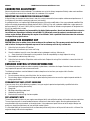
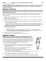
REPLACING THE SPARK PLUG
NOTICE! Using an incorrect spark plug can cause engine damage. Only replace a spark plug with a model
recommended by the manufacturer.
The spark plug must be properly gapped and free of deposits for the best performance. Check
local bylaws to see if a resistor spark plug is required to suppress ignition signals. Replace the
included spark plug with a resistor spark plug if required.
1. Remove any dirt from around the spark plug area.
2. Unclip the spark plug lead and remove the spark plug with a spark plug wrench. This will
have a rubber pad inside the socket to protect the spark plug’s ceramic coating.
3. Inspect the spark plug. Replace it if damaged, badly fouled, the sealing washer is in poor
condition or the electrode is worn.
4. Check the gap with a spark plug gauge as shown in Figure 6. If necessary, reset the gap
(See Specifications).
a. Correct the gap by carefully bending the side electrode. Check the gap after each
adjustment.
5. Install the spark plug carefully by hand to avoid cross threading.
6. Tighten the spark plug to the recommended torque until the gasket is compressed. See
Specifications for the correct torque rating.
a. Tighten an additional 1/2 to 1/3 turn more with a spark plug wrench if the torque rating isn’t available.
7. Reconnect the spark plug lead to the spark plug.
Fig. 6
Visit www.princessauto.com for more information 11

8509820 7,000W Gasoline Generator with Electric Start V 4.1
CARBURETOR ADJUSTMENT
Never make adjustments to the carburetor. The carburetor was set at the factory to operate efficiently under most conditions.
Only a qualified service technician should adjust the carburetor if it is required.
MODIFYING THE CARBURETOR FOR HIGH ALTITUDES
At high altitude, the standard air-fuel mixture is too rich, causing increased fuel consumption and decreased performance. A
rich mixture will also foul the spark plug and cause hard starting.
A qualified technician can improve high altitude performance with certain modifications. Have your carburetor modified if the
engine will routinely be operated at altitudes above 5,000 ft (1,524 m). Even with carburetor modification, engine power will
decrease about 3.5% for each 1,000 ft (305 m) increase in altitude. The effect of altitude on engine power will be greater than
this is if no modification is made.
NOTICE! When the carburetor has been modified for high altitude operation, the air fuel mixture will be too lean for
low altitude use. Operation at altitudes below 5,000 ft (1,500 m) may cause the engine to overheat and result in
serious engine damage. When using this engine at low altitudes, have a qualified technician return the carburetor
to original factory specifications.
CLEANING THE SEDIMENT CUP
CAUTION! Wear latex or rubber gloves when working on the sediment cup. The cup may contain fuel that will cause
skin irritation. Prolonged and repeated exposure to fuel on skin may result in dry, cracked skin.
1. Switch the fuel valve to the OFF position.
2. Remove the fuel sediment cup, screw and O-ring.
3. Clean the sediment cup with a non-flammable solvent or detergent and rinse. Allow to dry.
a. Some chemicals will damage the o-ring material. Check for compatibility or simply replace the o-ring.
4. Reassemble the sediment cup and o-ring.
5. Switch the fuel valve to the ON position and check for leaks. Replace the o-ring if the installation is correct, but fuel still
leaks from the cup.
EMISSION CONTROL SYSTEM INFORMATION
The combustion process produces carbon monoxide, hydrocarbons, and oxides of nitrogen. Control of these emissions is
very important for personal and environmental health.
The following instructions must be followed in order to keep the emissions from your engine within Canadian
emission standards.
1. Do not remove or alter any part of the intake, fuel, or exhaust systems.
2. Do not alter or bypass the governor linkage or speed-adjusting mechanism to cause the engine to operate outside its
design specifications.
PROBLEMS THAT MAY AFFECT EMISSIONS
If you are aware of any of the following symptoms, have your engine inspected and repaired by a qualified technician.
1. Hard starting or stalling after starting.
2. Rough idle.
3. Misfiring or backfiring under load.
4. Afterburning (backfiring)
5. Black exhaust smoke or high fuel consumption
REPLACEMENT PARTS
The emission control systems on your engine were designed, built, and certified to conform to Canadian emission regulations.
The use of genuine parts is recommended whenever maintenance is done to the engine. Genuine replacement parts are
manufactured to the same standards as the original parts. Using replacement parts that are not of the original design and
quality may impair the effectiveness of your emission control system.
It is the responsibility of the manufacturer of an aftermarket part to certify that use of the part will not result in a failure of the
engine to comply with emission regulations.
12 For technical questions call 1-800-665-8685

V 4.1 7,000W Gasoline Generator with Electric Start 8509820
BATTERY MAINTENANCE
1. Charge batteries in a designated, well-ventilated area to avoid gas buildup.
2. Charge the battery at rates recommended by the manufacturer.
3. Disconnect the charger from its power source before attaching or removing the clamp connections.
4. Carefully attach the clamps to the battery terminals based on their proper polarity.
5. Maintain the connections and the vent plug adjustment per the manufacture's recommendations. Also maintain the
vent caps to reduce the chance of electrolyte spray.
6. Clean the terminals and rinse off the battery's outer surface before recharging. Brush away from yourself when
cleaning debris from the battery and terminals to avoid potential contamination.
7. Fill sulfuric acid (electrolyte) to the prescribed level before charging to reduce the chances of the electrolyte heating
up excessively. If water is added, use distilled water. Do not use tap water due to impurities that can impact the
battery performance.
STORAGE
Proper storage preparation is essential for keeping your generator in good condition. The steps below will help to keep
rust and corrosion from impairing your generator's function and appearance and will make the generator easier to start
when used again.
The following precautions should be taken if storing your generator for a period exceeding 30 days or for
seasonal storage.
• Store in a clean dry area.
• Change the oil while the engine is still warm (see section How to Drain Oil).
• Clean the debris, chaff or grass from the engine's surface.
• Drain all fuel from the fuel tank into a proper receptacle for storage.
• Remove the spark plug. Place 1 teaspoon (5ml) of oil into the spark plug hole.
• Pull starter rope slowly 8-10 times to properly coat the cylinder bore and piston for storage. Replace spark plug and
tighten. Any residual oil will burn off in subsequent starts. This may result in white smoke emission from muffler.
• Pull the recoil starter rope again until you feel a slight resistance. Keep pulling until the arrow on the starting sleeve
aligns with the hole of the starter. When aligned, both the inlet and outlet valves are closed. This will help prevent
the engines from rusting inside.
• Store this generator in the horizontal position with the spark plug up. Do not store or transport with the spark plug
down. Storing or transporting with the spark plug down will result in hard starting and/or engine smoking.
• Prevent a build-up of explosive gases by storing the battery in a ventilated area or container that will disperse the
small amounts of gas created.
STORING GENERATOR WITH FUEL
WARNING! Keep the generator away from ignition sources such as sparks, the open flame of a pilot light when
storing with fuel in the tank. An ignition source can ignite gasoline vapours.
1. If your generator will be stored with gasoline in the fuel tank and carburetor, it is important to reduce the hazard of
gasoline vapour ignition.
a. Select a well-ventilated storage area away from any appliance that operates with a flame, such as a furnace,
water heater, or clothes dryer.
b. Avoid any area with a spark-producing electric motor.
c. Avoid any area where power tools are operated.
2. If possible, avoid storage areas with high humidity, as this promotes rust and corrosion.
3. Keep the generator level in storage. Tilting can cause fuel or oil leakage.
4. Cover the generator once the engine and exhaust system is cool. Some materials can ignite or melt if the engine
and/or exhaust system is hot. Do not use sheet plastic as a dust cover.
a. Use a cover made from a breathable fabric to prevent rust and corrosion.
Visit www.princessauto.com for more information 13

8509820 7,000W Gasoline Generator with Electric Start V 4.1
REMOVAL FROM STORAGE
1. Check the generator as described in the section Pre-Operation Checks.
2. If the fuel was drained during storage preparation, fill the tank with fresh gasoline.
3. If the cylinder was coated with oil during storage preparation, the engine will smoke briefly at start up.
This is normal.
TRANSPORTING THE GENERATOR
WARNING! Transport the generator with an empty fuel tank or with the fuel valve lever secured in the OFF position.
1. Keep the generator level when transporting to reduce the possibility of fuel leakage.
2. Turn the fuel valve (I) to the OFF position.
FUEL STORAGE
Gasoline will oxidize and deteriorate in storage. Deteriorated gasoline makes it harder to start the engine and leaves gum
deposits that clog the fuel system. If that gasoline in your engine deteriorates during storage, you may need to service or
replace the carburetor and other fuel system components.
The length of time that gasoline can be left in your fuel tank and carburetor without causing functional problems will vary
with factors such as gasoline blend, storage temperatures and the amount of fuel in the tank. The air in a partially filled
fuel tank will promote fuel deterioration, as will very warm storage temperatures. Fuel problems may occur in a few
months, or sooner if the gasoline was not fresh when the tank was filled.
Adding a gasoline stabilizer that is formulated for this purpose can extend fuel storage life. Deterioration problems can
also be avoided by draining the fuel tank and carburetor prior to storage.
ADDING A GASOLINE STABILIZER
1. Fill the fuel tank with fresh gasoline. If the tank is only partially filled, air in the tank will promote fuel deterioration
during storage.
2. Add gasoline stabilizer. Ensure that the instructions for that product are followed.
3. Run the generator outdoors for 10 minutes to ensure that treated gasoline has replaced the untreated gasoline in
the carburetor.
4. Stop the engine.
CLEANING
WARNING! Use only a nonflammable solvent, not gasoline, to clean engine parts. Keep all sources of ignition away
from fuel related parts. Fumes are flammable and may catch fire, causing a burn injury.
NOTICE! Do not clean the engine’s exterior with a garden hose or pressure washer. Water can enter the engine
through the air filter or muffler opening and damage the cylinder.
1. If the generator has been running, allow it to cool for at least half an hour before cleaning.
2. Clean all exterior surfaces.
3. Touch up any damaged paint.
4. Coat other areas that may rust with a light film of oil.
DISPOSAL
Recycle a generator damaged beyond repair at the appropriate facility.
Contact your local municipality for a list of disposal facilities or by-laws for electronic devices, batteries, oil or other toxic
liquids.
IMPORTANT! DO NOT pollute the environment by allowing uncontrolled discharge of waste oil.
14 For technical questions call 1-800-665-8685

V 4.1 7,000W Gasoline Generator with Electric Start 8509820
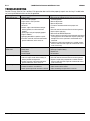
TROUBLESHOOTING
Contact Princess Auto Ltd. for a solution if the generator does not function properly or parts are missing. If unable to do
so, have a qualified technician service the generator.
Problem(s)
Possible Cause(s)
Suggested Solution(s)
Engine will not start.
1. Engine is cold.
2. Fuel valve in OFF position.
3. Engine switch is in OFF position.
4. Engine oil is low.
5. Out of fuel.
6. Bad fuel, engine stored without treating or
draining gasoline, or refueled with bad
gasoline.
7. Spark plug is faulty or improperly gapped.
8. Engine is flooded.
9. Spark plug fouled/fails to produce a spark.
10. Fuel filter restricted, carburetor malfunction,
ignition malfunction, valves stuck, etc.
1. Move choke to CLOSED position until warm, then move to
the OPEN position.
2. Move to ON position
3. Move to ON position
4. Fill with the recommended oil to the proper level.
5. Refuel.
6. Drain fuel tank and carburetor. Refuel with fresh gasoline.
7. Gap or replace spark plug
8. Move choke to OPEN/RUN position
9. Remove and clean spark plug. Check electrode spacing and
set the gap to the correct dimension. Replace spark plug if
damaged. Ensure the spark lead is installed and wire is
connected.
10. Replace or repair faulty components as needed. Contact
Princess Auto Ltd or take engine to an authorized service
center if necessary.
Engine will not start,
electric start.
1. Power cord damaged.
2. Battery dead.
3. Fuse tripped.
3. Breaker tripped.
1. Repair or replace power cord.
2. Recharge or replace battery.
3. Replace fuse.
3. Reset breaker.
Engine lacks power.
1. Filter element(s) restricted.
2. Stale fuel, engine stored without treating or
draining ethanol based gasoline.
3. Fuel filter restricted, carburetor malfunction,
ignition malfunction, valves stuck, etc.
1. Clean or replace filter element(s).
2. Drain fuel tank and carburetor. Refuel with fresh gasoline.
3. Replace or repair faulty components as needed. Contact
Princess Auto Ltd or take engine to an authorized service
center if necessary.
No power generated
1. Main switch is not closed.
2. Contact of socket is not sufficient.
3. Rated speed of generator cannot be reached.
1. Turn main switch to ON position.
2. Adjust the feet of the socket.
3. Adjust according to requirement in manual.
Visit www.princessauto.com for more information 15

8509820 7,000W Gasoline Generator with Electric Start V 4.1
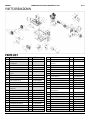
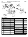
PARTS BREAKDOWN
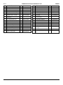
PARTS LIST
# DESCRIPTION QTY PARTS ID
1 UP190E EPA-III/CARB 1 012080000056
2 Hexagon Nut with
Flange M8
12 512040800001
3 Shock Absorption 4 029910300301
4 Flange Screw M10 5 512041000000
5 Flange Bolt B-M5X12 5 511050501201
6 Crankcase Windshield
Cover
1 029990000701
7 Rotor Assy 1 062023420001
8 Washer C-10 (H = 3 mm) 1 513041000006
9 Spring Washer 10 1 513021000002
10 Hexagon Bolt M10X270 1 511011027001
11 Stator 1 062023430002
12 Alternator Guard Board
620X135
1 029030102501
13 Spring Washer 6 7 513020600002
14 Flange Bolt B-M6X185 4 511050618501
15 190 Rear End Cover 7 1 029030430700
16 Lock Washer 5 2 513030500000
17 Flat Washer C-5 8 513010500001
18 Spring Washer 5 5 513020500000
19 Flange Bolt B-M5X16 7 511050501601
20 Hexagon Bolt C-M5X20 3 511140502000
21
Connection Pole (Orange)
1
029030500101
22 Hex Nut C-M5 6 512010500001
23 Carbon Brush 2 1 029030700200
24 5 kw AVR CSA 1 029030620204
25 190 Rear End Cover
Guard 1
1 029030300314
26 Muffler Gasket-6 1 029049910600
27 Flat Washer C-8 2 513010800001
28 Spring Washer 8 2 513020800002
29 Muffler -19 1 029040600019
30
Flange Bolt B-M8X20
2
511050802001
31 Screw M6*20 2 515010602003
32 Gulp Valve 1 029049950100
33 Flange Bolt B-M8X40 2 511050804001
34 Flange Bolt B-M6X12 8 511050601201
35 Bolt M8X25 4 510050802501
36 Washer C-8 1 513040800000
37 Fuel Tank Shock
Absorption 1
4 029019910001
38 Fuel Tank 25L Honey Well 1 02901480024104
39
Φ 7 Clamp
1 029019900408
40
Φ 7.5 Fuel Pipe
1 029019900200
41
Φ 8 Clamp
1 029019900401
42 Fuel Cock Assy-04 1 029019900704
43
Φ 13 Clamp
2 029019900402
44
Φ 4.5*8.5 mm Fuel Pipe
1 029019902100
45 Fuel Gauge 1 029019930000
46 Fuel Tank Cap 1 02901990111004
16 For technical questions call 1-800-665-8685

V 4.1 7,000W Gasoline Generator with Electric Start 8509820
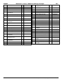
47 Fuel Tank Filter-06 1 029019900606
48 Flange Bolt B-M6X14 11 511050601401
49 Flat Washer C-6 3 513010600001
50 Lock Washer 6 1 513030600000
51 Hexagon Nut with Flange M6 13 512040600001
52 Frame 1 022152500001
53 Support Chip, Fuel Tank 2 022152420001
54 Shock Absorber, Rear
end Cover
1 029911300101
55 17 Control Panel Assy. 1 029027100079
56 Screw ST4.2X12 4 517050401204
57 Muffler Side Hood 1 029940102201
58 Muffler Safeguard Cover 1 029940102301
59 Muffler Back Hood 1 029940102401
60 Wire, Battery 250 mm 1 029969900230
61 Battery 12AH 1 029960200100
62 Wire, Battery 150 mm 1 029969900220
63 Platen, Battery 9AH 1 029960900901
64 Circlip for Shaft 2 518020120000
65 Flat Washer C-12 2 513011200000
66 Wheel 2 029050400100
67 Flat Washer C-16 2 513011600001
68 110 Axle 2 029050411000
69 6145 Plug Pin 2 029050290004
70 Screw M6 1 512070600000
71 Handle Supporting
Structure Assy
1 029050420001
72 Flange Bolt B-M6X40 1 511050604001
73 Handle Pad 1 029050400201
74 Handle 1 029050400701
75 22 Handle Cover 1 029050100701
76 Flange Bolt B-M8X16 4 511050801601
77 Supporting Structure,
Foot Pad
1 029050400401
78 Foot Pad 2 029050400300
79 Grounding Wire (12 cm)
Φ
6
1 029930000701
Visit www.princessauto.com for more information 17

8509820 7,000W Gasoline Generator with Electric Start V 4.1
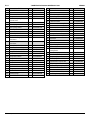
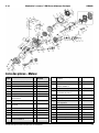
PARTS LIST - ENGINE
# DESCRIPTION QTY PARTS
IDENTIFIER
1 Flange Bolt B-M8X45 7 511050804501
2 Spring Washer 8 7 513020800002
3 Flat Washer C-8 8 513010800002
4 Oil Seal (F) B3552 2 522010100601
5 Crankcase Cover 1 012050003000
6 Dipstick (27 mm) 1 012050003142
7 Gasket, Crankcase 1 012050000400
8 Round pin 8X14 2 514010801400
9 Piston Pin Circlip 20 2 518042000000
10 Connecting Rod Assembly 1 012050300000
11 Piston Pin 1 012050001200
12 Piston 1 012080001100
13 Piston Ring Set 1 012080200000
14
Deep Groove Ball Bearing
60000-35
1
521010010301
15 Crankshaft Assembly
V3 ROHS
1 012080001301
16 Camshaft Assembly 1 012080001600
17 Deep Groove Ball Bearing
60000-15
2 521010010601
18 Balancing Shaft ROHS 1 012080600000
19 Speed Swing Rod Gasket 2 019990000600
20
Driven Gear Assembly
1
012050100000
21 Regulating Shaft 1 019990002100
22 Snap Ring, Regulating Shaft 1 012020000600
23 Tappet 1 019990001900
24 Flange Bolt B-M6X12 11 511050601201
25 Oil Sensor 1 019990003700
26 Valve Lifter 2 019990003500
27 Flange Bolt B-M8X45 2 012050000900
28 Push Guide Assembly 1 012041700000
29
Rocker Arm Assembly
2
019990002700
30 Crankcase (Electric Start) 1 012080000100
31 Washer 12, Drain Plug 2 019990001500
32 Drain Plug M12X14 2 019990001400
33 Round Pin 12X20 2 514011202000
34 Cylinder Head Gasket 1 012080000800
35 Intake Valve ROHS 1 012080001700
18 For technical questions call 1-800-665-8685

V 4.1 7,000W Gasoline Generator with Electric Start 8509820
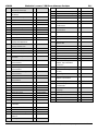
36 Exhaust Valve ROHS 1 012080001800
37 Stud B-M8X34 2 516040803401
38 Cylinder Head Cover ROHS 1 012080000500
39 Underneath Shroud 1 012050001000
40 Flange Bolt B-M10X80 4 511051008006
41 Underneath Spring Retainer,
Exhaust Valve
1 019990003300
42 Oil Seal, Intake Valve Duct 1 019990003400
43 Valve Spring 2 012080002200
44 Valve spring retainer 2 012080002100
45 Valve Key 4 012080001900
46 Exhaust Valve, Cap 2 019990002900
47 Gasket, Cylinder Head Cover 1 019990002600
48 Cylinder Head Cover 1 012041800000
49 Bolt Rubber Ring, Cylinder
Head Cover
1 019990002400
50 Bolt Gasket, Cylinder
Head Cover
1 019990002300
51 Bolt, Cylinder Head Cover 1 019990002200
52 Crankcase Rubber Ring 1 019990001800
53 Starting Motor Assembly 1 012051000000
54 Flange Bolt B-M8X35 2 511050803501
55 Diode 1 019990001700
56 Flange Bolt B-M6*8 4 511050600807
57 Charge Coil 1 012022200001
58 Flange Bolt B-M6X28 2 511050602803
59 Clamper, Cord 1 012050002900
60 Flywheel 1 012051200000
61 Ignition Coil Assembly 1 012050001700
62
Flange Bolt B-M6X22
2
511050602201
63 Flywheel Fan 1 012050001400
64 Starting Flange 1 012050003200
65 Flywheel Nut M16X1.5 1 019990003600
66 Shroud 1 012050001542
67 Rubber Block 1 012020005200
68 Clip 2 019990005000
69 Recoil Starter Assembly 1 012053200043
70 Spark Plug F7TC 1 019990003800
71 Stud A- M8*116 2 516050811601
72 190 Inlet Gasket 1 012080002300
73 Carburetor Connecting Block 1 012050001902
74 Carburetor Gasket 1 012050002000
75 Carburetor Assembly EPA-III 1 01209090000504
76 Gasket, Air Cleaner 1 019990004400
77 Chock Valve 1 019990004900
78 Hexagon Nut with Flange M6 3 512040600001
79 Air Cleaner Assembly 1 012041600002
80
Vent Pipe
1
012080004000
81 Clip 1 019990004500
82 Check Valve 1 019990004800
83 Speed Swing Rod 1 012050000200
84 Oil Seal (F) B0814 1 522010101301
85 Valve Lock Clamp, Speed
Swing Rod 2
1 019990001600
86 Governor Spring 1 012050002200
87 Lock Bolt (27 mm) 1 012020004500
88 Regulating Arm 1 012050002600
89 Reset Sprig, Throttle Valve 1 012050002300
90 Speed Governing Pull Rod 1 012050002400
91 Regulating Control Assembly 1 0120513100000
92 Washer, Regulating Sway Bar 1 019990005100
93
Air Cleaner Bracket
1
012041600401
94 Plan Washer C-6 1 513040600000
95 Flange Bolt B-M6X14 1 511050601401
96 Attaching Clamp, Oil Pipe 1 029019902900
Visit www.princessauto.com for more information 19

8509820 7,000W Gasoline Generator with Electric Start V 4.1
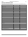
WATTAGE REFERENCE CHART
Electric equipment, especially engine produce strong current when being started. The following table offers references
when you connect those installations to the generator.
Tool or Appliance Rated * (Running) Watts Additional Surge (Starting) Watts
Essentials
Light Bulb – 75 watt, 75 -
Deep Freezer 500 500
Sump Pump 800 1,200
Refrigerator / Freezer – 18 Cu. Ft. 800 1,600
Water Well Pump – 1/3 HP 1,000 2,000
Heating / Cooling
Window Air Conditioner – 10,000 BTU 1,200 1,800
Window Fan 300 600
Furnace Fan Blower – 1/2 HP 800 1,300
Kitchen
Microwave Oven – 1,000 watt 1,000 -
Coffee Maker 1,500 -
Electric Stove – Single Element 1,500 -
Hot Plate 2,500 -
Family Room
DVD / CD Player 100 -
VCR 100 -
Stereo Receiver 450 -
Colour Television – 27 in. 500 -
Personal Computer with 17 in. Monitor 800 -
Other
Security System 180 -
AM / FM Clock Radio 300 -
Garage Door Opener – 1/2 HP 480 520
Electric Water Heater – 40 Gallon 4,000 -
DIY / Job Site
Quartz Halogen Work Light
1,000
-
Airless Sprayer – 1/3 HP
600
1,200
Reciprocating Saw 960 960
Electric Drill – 1/2 HP 1,000 1,000
Circular Saw – 7-1/4 in. 1,500 1,500
Miter Saw – 10 in. 1,800 1,800
Table Planer – 6 in. 1,800 1,800
Table Saw / Radial Arm Saw – 10 in. 2,000 2,000
Air Compressor – 1-1/2 HP 2,500 2,500
Wattages listed are approximate only. Check tool or appliance for actual wattage.
20 For technical questions call 1-800-665-8685
La page est en cours de chargement...
La page est en cours de chargement...
La page est en cours de chargement...
La page est en cours de chargement...
La page est en cours de chargement...
La page est en cours de chargement...
La page est en cours de chargement...
La page est en cours de chargement...
La page est en cours de chargement...
La page est en cours de chargement...
La page est en cours de chargement...
La page est en cours de chargement...
La page est en cours de chargement...
La page est en cours de chargement...
La page est en cours de chargement...
La page est en cours de chargement...
La page est en cours de chargement...
La page est en cours de chargement...
La page est en cours de chargement...
La page est en cours de chargement...
La page est en cours de chargement...
La page est en cours de chargement...
La page est en cours de chargement...
La page est en cours de chargement...
-
 1
1
-
 2
2
-
 3
3
-
 4
4
-
 5
5
-
 6
6
-
 7
7
-
 8
8
-
 9
9
-
 10
10
-
 11
11
-
 12
12
-
 13
13
-
 14
14
-
 15
15
-
 16
16
-
 17
17
-
 18
18
-
 19
19
-
 20
20
-
 21
21
-
 22
22
-
 23
23
-
 24
24
-
 25
25
-
 26
26
-
 27
27
-
 28
28
-
 29
29
-
 30
30
-
 31
31
-
 32
32
-
 33
33
-
 34
34
-
 35
35
-
 36
36
-
 37
37
-
 38
38
-
 39
39
-
 40
40
-
 41
41
-
 42
42
-
 43
43
-
 44
44


Power Fist 8509820 Le manuel du propriétaire
- Catégorie
- Groupes électrogènes
- Taper
- Le manuel du propriétaire
dans d''autres langues
- English: Power Fist 8509820 Owner's manual
Documents connexes
-
Power Fist 8261562 Parts list
-
-
-
-
-
-
-
-
-
Autres documents
-
Powerfist 8449019 Le manuel du propriétaire
-
-
-
PROPOINT 8999153 Le manuel du propriétaire
-
-
Anova P101 Le manuel du propriétaire
-
Energizer eZG7250CA Manuel utilisateur
-
 pro.point 8630741 Manuel utilisateur
-
-
 PRO POINT 8953135 Manuel utilisateur

