
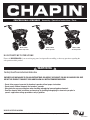
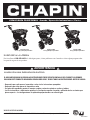
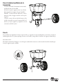
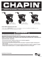
PROFESSIONAL SPREADER Assembly / Operation Instructions / Parts
CHAPIN INTERNATIONAL, INC. P.O. BOX 549 700 ELLICOTT ST. BATAVIA, NY 14021-0549 www.chapinmfg.com 800-950-4458
Please call 800-950-4458 if you are missing any parts, having trouble assembling, or have any questions regarding the
safe operation of this product.
DO NOT RETURN TO THE STORE
MODEL 82125/82100/82080
Carefully Read These Instructions Before Use
IMPROPER USE OR FAILURE TO FOLLOW INSTRUCTIONS CAN RESULT IN PRODUCT FAILURE OR INJURIES. FOR SAFE
USE OF THIS PRODUCT YOU MUST READ AND FOLLOW ALL INSTRUCTIONS BEFORE USING.
- Do not allow anyone to operate the broadcast spreader without proper instructions
- Do not permit children to operate the broadcast spreader
- Wear protective eyewear and gloves when handling and applying lawn and garden chemicals
- Read the chemical label instructions and warnings for handling and applying the chemicals you plan to
spread – application settings provided are only a guideline
WARNING
Model 82100
100 lb. Spreader
Model 82125
125 lb. Spreader
Model 82080
80 lb. Spreader
011973 R0713

ASSEMBLY INSTRUCTIONS
Suggested Tools:
Wrench and/or Ratchet Set
1.5mm Allen Wrench
Pliers
Protective Eyewear
Approximate assembly time is 20-45 minutes
CHAPIN INTERNATIONAL, INC. P.O. BOX 549 700 ELLICOTT ST. BATAVIA, NY 14021-0549 www.chapinmfg.com 800-950-4458
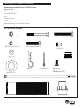
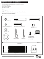
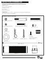
Full scale nuts and bolts
NOTE: Depending on model, this package may contain
additional hardware not needed for assembly.
M5 Nylon Locknut (1)
M6 Nylon Locknut (7) M6 x 55mm Hex Bolt (6) M6 x 45mm Hex Bolt (1)
M5 x 35mm Hex Bolt (1)
Spacer (4)
Flat Washer (1)
R- Pin (1) Cotter Pin (1)
#8-18 x 1/2
read-Forming
Phillips Screw (1)
P-Clamp (1)
End Cap (2)
Cable Tie (2)
Hand Grip (2) Bushing (2)

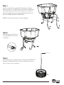
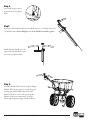
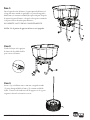
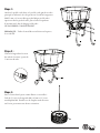
Step 1:
Attach the right Frame leg and the le Frame leg to the Frame
Body using 2 spacers, (2) M6X55mm hex bolts and (2) M6 Nylon
locknuts per frame leg. Aer the frame legs have been attached,
place the two End caps onto the bottom of both frame legs. DO
NOT TIGHTEN DOWN COMPLETELY.
NOTE: Use bottom hole pattern on legs if equipped.
CHAPIN INTERNATIONAL, INC. P.O. BOX 549 700 ELLICOTT ST. BATAVIA, NY 14021-0549 www.chapinmfg.com 800-950-4458
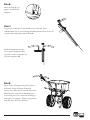
Step 2:
Slide bushings into the holes on
the hopper frame from outside
of the frame.
Step 3:
Insert Axle into Tire as shown and secure using (1) M6 x 45mm Hex
Bolt and (1) M6 Nylon Locknut. Take note of hole locations on
Axle, to ensure correct orientation.
Hole at top

CHAPIN INTERNATIONAL, INC. P.O. BOX 549 700 ELLICOTT ST. BATAVIA, NY 14021-0549 www.chapinmfg.com 800-950-4458
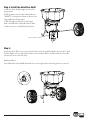
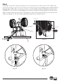
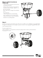
Step 4: Install the Axle/Drive Shaft
a. Slide the Drive sha through one side of the
hopper frame
b. Slide gearbox onto axle/drive sha (make sure
“FRONT” is facing front of frame as shown) and
align middle hole with gearbox
c. Slide through the other side of the hopper
frame. Assemble M5 x 35mm Hex bolt to Axle/
Gearbox and secure with M5 Nylon Locknut.
Step 5:
Attach non-drive Wheel onto exposed end of Axle and secure with Flat Washer & Cotter Pin. Slide
the Flat Washer onto the Axle until it makes contact with the Wheel, and then slide the Cotter Pin
into the hole at the end of the Axle.
Additional Notes:
Drive Sha: Hole Near Middle should be closer to the right wheel so that the gear box is centered.
Bend
M5 x 35mm Hex bolt

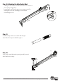
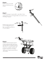
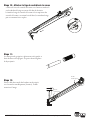
Step 8:
Assemble Handle Tube to Frame Legs by sliding
Handle Tube into the gap between the two parts
and using (2) M6X55mm bolts and (2) M6
Nylon Locknuts to connect the parts together.
Handle orientation is important (see image).
Finish tightening frame legs to the frame body.
CHAPIN INTERNATIONAL, INC. P.O. BOX 549 700 ELLICOTT ST. BATAVIA, NY 14021-0549 www.chapinmfg.com 800-950-4458
Step 6:
Look inside hopper. Insert
R-pin into hole in impeller
sha.
Step7:
A portion of the Handle will be preassembled as shown. Carefully remove the
(2) M6 Hex Nuts, while holding the rest of the Handle Assembly together.
Install opposite Handle onto the
exposed (2) M6 Hex Bolts, and re-
secure the (2) M6 Hex Nuts.

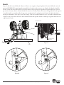
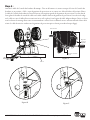
Step 9:
Attach Edge Control cable. Turn spreader upside down for step 9 (if possible set on table as shown) Note: While doing
this make sure the Edge Control lever is in the ON position and the trim guard itself is making contact with the bottom of
the hopper base. Slide the Wire onto the hole on the wire control barrel (Fig. A). Pull wire through barrel until it is taute.
Tighten the Set screw onto the wire with aPhillips head screw driver. Next take a P-clamp and place it on the cable sheath.
Align so P-clamp is under mount post. Take a self tapping screw and screw the P-clamp into the hole on the bottom of the
hopper base (Fig. B & C). e wire should be tight so the trim guard doesn’t fall when released.
CHAPIN INTERNATIONAL, INC. P.O. BOX 549 700 ELLICOTT ST. BATAVIA, NY 14021-0549 www.chapinmfg.com 800-950-4458
Figure B Figure C
Cable Sheath
Wire Control
Barrel
Tighten
Figure A
Trim Guard
Table

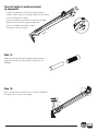
Step 10: Attaching the Gate Control Rod
a. Slide gate control lever forward and attach hook at bottom of
rod to spring at hopper base
b. Attach gate control rod to upper screw on gate control by
removing the screw rst, attaching the rod, and then
re-attaching the screw
Step 11:
Both Hand Grips slide onto both the le and right
handle bars. e Grips should Slide right on.
CHAPIN INTERNATIONAL, INC. P.O. BOX 549 700 ELLICOTT ST. BATAVIA, NY 14021-0549 www.chapinmfg.com 800-950-4458
Step 12:
Secure edge control cable with zip ties (provided) onto the
handle as shown in image.
Zip tie
Zip tie

CHAPIN INTERNATIONAL, INC. P.O. BOX 549 700 ELLICOTT ST. BATAVIA, NY 14021-0549 www.chapinmfg.com 800-950-4458
99
1
2
4
5
7
10
3
8
11
6
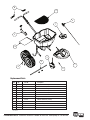
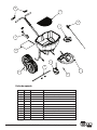
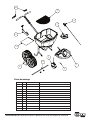
Replacement Parts
Ref.# Qty Part No. Description
1 1 6-9008 Hopper Base Assembly
2 1 6-9010 Gear Box Assembly
3 1 6-9009 Drive Shaft w/2 bearings
4 1 6-9011 Edge Control Assembly
5 1 6-9012 Gate Control Assembly
6 1 6-9013 R Pin
7 1 6-9014 Impeller
8 1 6-9015 Wheels w/hardware (red rim)
9 1 6-9016 Handle Grips
10 1 6-9017 Hardware Bag
11 1 6-9001 Grate
* 1 6-9000 Rain Cover
* Not Shown

CHAPIN INTERNATIONAL, INC. P.O. BOX 549 700 ELLICOTT ST. BATAVIA, NY 14021-0549 www.chapinmfg.com 800-950-4458
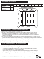
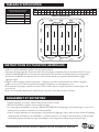
START RESTART RESTART
RESTART RESTART
SHUT OFF HERE SHUT OFF HERE
SHUT OFF HERE SHUT OFF HERE
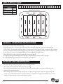
Sample Spread Pattern
• Whennishedspreadingemptyhopperofanyremainingmaterial.
• oroughlywashspreaderandallowtodrybeforestoring.
• Gearsarepermanentlylubricatedatthefactory.DONOTopenthegearboxatanytimeasdebrismayenter
and interfere with functionality.
• Whenusingrocksaltandice-meltproductsbesuretoemptythehopperuponcompletionofspreadingeach
time you use it. ese materials may reconstitute back into a solid block overnight with humidity. ey can also
damage metal parts if exposed for extended periods of time.
STORAGE AND MAINTENANCE
Scotts 2 2.5 3 3.25 3.5 4 4.75 5 5.5 6 7 8 9 10 11 12 13 14 15
Chapin 9 10 11 12 13 14 15 16 17 18 19 20 21 22 23 24 25 26 27
All Season Residential & Professional Push Spreader Application Conversion Chart
All Season Residential &
Professional General Application
Guidelines
Weed Control
Fertilizer
Grass Seed - Overseeding
Grass Seed - New Lawn
Salt & Ice-Melt
10-12
12-16
16-20
21-27
28-30
APPLICATION CHART
•Besuregatecontrolisintheclosedposition.
•Determineappropriatesettingformaterialbeingusedbyreadingthesuggestedsettingonthematerial’sbag
AND/OR by referencing the application chart on your spreader’s control panel (Charts provided are only guidelines.
Be sure to read the instructions on the bag/box of the material you’re spreading to identify accurate setting needed)
•SetthedialtothedesiredsettingImportant Note: Do not adjust dial with gate open.
is will alter the accuracy of gate settings and cause parts to break.
•Tobeginspreading,startwalking(about3mphpace)andpullthegatecontroldowntoopengate.
•Tostopspreadingsimplypushgatecontrolupandthegatewillclose.
GENERAL OPERATING INSTRUCTIONS

ESPARCIDORA PROFESIONAL Armado / Operación Instrucciones / Partes
CHAPIN INTERNATIONAL, INC BOX 549 700 ELLICOTT ST. BATAVIA, NY 14021-0549 www.chapinmfg.com 800-950-4458
Por favor llame al 800-950-4458 si le falta alguna parte, si tiene problemas con el armado o si tiene alguna pregunta sobre
la operación segura de este producto.
NO DEVUELVA A LA TIENDA
MODEL 82125/82100/82080
Lea estas instrucciones atentamente antes de utilizarlo
EL USO INAPROPIADO O NO SEGUIR LAS INSTRUCCIONES PUEDE RESULTAR EN FALLAS DEL PRODUCTO O LESIONES.
PARA USAR ESTE PRODUCTO DE MANERA SEGURA DEBE LEER Y SEGUIR TODAS LAS INSTRUCCIONES ANTES DE USARLO.
- No permita que nadie opere el esparcidor a voleo sin las instrucciones apropiadas
- No permita que niños operen el esparcidor a voleo
- Use gafas de seguridad y guantes al manejar y aplicar sustancias químicas a patios y jardines
- Lea las instrucciones y advertencias químicas en la etiqueta respecto al manejo y aplicación de las sustancias que
planea esparcir – las configuraciones de aplicación proporcionadas son sólo una guía
ADVERTENCIA
Model 82100
45 kg (100 lb) Esparcidora
Modelo 82125
57 kg (125 lb) Esparcidora
Model 82080
36 kg (80 lb) Esparcidora
011973 R0713

INSTRUCCIONES DE ARMADO
Herramientas sugeridas:
Juego de llaves y/o matracas
Llave Allen de 1.5 mm
Pinzas
Gafas de seguridad
El tiempo aproximado de armado es de 20-45 minutos
CHAPIN INTERNATIONAL, INC BOX 549 700 ELLICOTT ST. BATAVIA, NY 14021-0549 www.chapinmfg.com 800-950-4458
Pernos y tuercas a escala completa
NOTA: Dependiendo del modelo, este paquete puede contener hardware
adicional no necesario para el ensamblaje.
Contratuerca M5 Nylon (1)
Contratuerca M6 Nylon ) M6 x 55mm Hex Bolt (6)
Perno hexagonal M6 x 45mm (1)
Perno hexagonal M5 x 35mm (1)
Espaciador (4)
Arandela plana (1)
Clavija en R (1) Chaveta (1)
Tornillo Phillips
formador de rosca
#8-18x1/2 (1)
Abrazader-P (1)
Tapa para extremo (2)
Sujetacable (2)
Empuñadura (2) Cojinete (2)

Paso 1:
Sujete la pata derecha del marco y la pata izquierda del marco al
cuerpo del marco usando 2 espaciadores, 2 pernos hexagonales
M6x55mm y 2 contratuercas M6 Nylon para cada pata. Después
de sujetar las patas del marco, coloque los dos tapones terminales
en la parte inferior de ambas patas del marco.
NO APRIETE LAS TUERCAS COMPLETAMENTE.
NOTA: Use el patrón de agujeros inferior si está equipado.
CHAPIN INTERNATIONAL, INC BOX 549 700 ELLICOTT ST. BATAVIA, NY 14021-0549 www.chapinmfg.com 800-950-4458
Paso 2:
Deslice los bujes en los agujeros
del marco de la tolvilla desde la
parte exterior del marco.
Paso 3:
Inserte el eje en la llanta como se muestra y asegúrelo usando
(1) perno hexagonal M6 x 45 mm y (1) contratuerca M6 de
nylon. Tome nota de la ubicación de los agujeros en el eje para
asegurarse de usar la orientación correcta.

CHAPIN INTERNATIONAL, INC BOX 549 700 ELLICOTT ST. BATAVIA, NY 14021-0549 www.chapinmfg.com 800-950-4458
Paso 4: Instale el eje/flecha de la
transmisión
a. Deslice la echa de la transmisión atravesando
un lado del marco de la tolvilla.
b. Deslice la caja de engranes sobre el eje/echa
de la transmisión (asegúrese de que la palabra
‘FRONT’ esté hacia el frente del marco, como se
muestra) y alinee el agujero medio con la caja de
engranes.
c. Deslice a través del otro lado del marco de la
tolvilla. Atornille un perno hexagonal M5 x 35
mm al eje/caja de engranes y asegúrelo con una
contratuerca M5 de nylon.
Paso 5:
Sujete la llanta sin impulsión al extremo expuesto del eje y asegúrela con una arandela plana y una chaveta. Deslice la
arandela plana sobre el eje hasta que haga contacto con la rueda, y luego deslice la chaveta en el agujero al nal del eje.
Notas adicionales:
Flecha de la transmisión: El agujero cerca de la parte media debe estar más cerca de la rueda derecha de tal modo que
la caja de engranes quede centrada.
Bend

CHAPIN INTERNATIONAL, INC BOX 549 700 ELLICOTT ST. BATAVIA, NY 14021-0549 www.chapinmfg.com 800-950-4458
Paso 6:
Inserte la clavija-R en el
agujero en la echa del
impulsor.
Paso 7:
Una parte de la manija estará prearmada como se muestra. Retire
cuidadosamente las (2) tuercas hexagonales M6 mientras sujeta el resto del
conjunto de la manija para mantenerlo unido.
Instale la manija opuesta sobre
los (2) pernos hexagonales M6
expuestos, y vuelva a sujetar las (2)
tuercas hexagonales M6.
Paso 8:
Sujete el tubo del mango a las patas del marco
deslizando el tubo del mango dentro del
espacio entre ambas partes y usando dos pernos
M6x55mm y 2 contratuercas M6 Nylon para
conectar las partes. La orientación del mango es
importante (ver imagen). Termine de apretar las
patas del marco al cuerpo del marco.

Paso 9:
Sujete el cable del control del borde. Observe: Al hacer esto, asegúrese de que la palanca del control del borde está en la
posición ENCENDIDO y que la guarda misma del borde está haciendo contacto con el fondo de la base de la tolvilla.
Deslice el cable del control del borde a través de la ranura en la parte superior izquierda de la guarda del borde. Una vez
que atraviese la ranura, deslice el barril del cable de control en el cable y dentro de la ranura en la guarda del borde. Apriete
el tornillo al cable con una llave Allen. Luego tome una abrazadera P y colóquela sobre la funda del cable. Alinéela de
modo que la abrazadera P esté bajo el poste de montaje. Tome un tornillo formador de rosca y atornille la abrazadera P en
el agujero en la parte inferior de la base de la tolvilla. El cable debe quedar estirado de modo que la guarda del borde no se
caiga cuando la suelte.
CHAPIN INTERNATIONAL, INC BOX 549 700 ELLICOTT ST. BATAVIA, NY 14021-0549 www.chapinmfg.com 800-950-4458
Figura C
Figura B
Envoltura de cable
Barril del control
de alambre
Apriete
Figure A
Guardia del
ajuste
Vector

Paso 10: Sujetar la varilla de control
de compuerta
a. Deslice la palanca de control de la compuerta hacia
adelante y sujete el gancho en la parte inferior de la varilla al
resorte en la base de la tolvilla.
b. Sujete la varilla de control de la compuerta al tornillo
superior del control de la compuerta quitando
primero el tornillo, sujetando la varilla y
volviendo a colocar el tornillo.
Paso 11:
Ambas cubiertas de manijas se deslizan sobre las manijas
izquierda y derecha. Las cubiertas deben deslizarse con
facilidad.
CHAPIN INTERNATIONAL, INC BOX 549 700 ELLICOTT ST. BATAVIA, NY 14021-0549 www.chapinmfg.com 800-950-4458
Paso 12:
Sujete el cable del control del borde con cinchos (incluidos) a
la manija como se muestra en la imagen.
Cincho
Cincho

CHAPIN INTERNATIONAL, INC BOX 549 700 ELLICOTT ST. BATAVIA, NY 14021-0549 www.chapinmfg.com 800-950-4458
99
1
2
4
5
7
10
3
8
11
6
Partes de repuesto
Num. Ref Cant. Num. Parte Descripción
1 1 6-9008 Conjunto de la base de la tolvilla
2 1 6-9010 Conjunto de la caja de engranes
3 1 6-9009 Flecha de transmisión c/2 cojinetes
4 1 6-9011 Control del borde
5 1 6-9012 Conjunto del control de la compuerta
6 1 6-9013 Clavija R
7 1 6-9014 Impulsor
8 1 6-9015 Ruedas C/herrajes (rin rojo)
9 1 6-9016 Cubiertas de manijas
10 1 6-9017 Bolsa de herrajes
11 1 6-9001 Parrilla
* 1 6-9000 Cubierta para lluvia
* Not Shown

CHAPIN INTERNATIONAL, INC BOX 549 700 ELLICOTT ST. BATAVIA, NY 14021-0549 www.chapinmfg.com 800-950-4458
• Cuandoterminededistribuirvacíelatolvadecualquiermaterialrestante.
• Lavebieneldistribuidorydéjelosecarantesdeguardarlo.
• Losengranajesvienenlubricadospermanentementedefábrica.NOabralacajadevelocidadesenningún
momento, pueden entrar desechos e interferir con la funcionalidad.
• Cuandoseutilizasalderocayproductosquesederritenasegúresedevaciarlatolvaalterminardedistribuir
cada vez que lo utilice. Estos materiales pueden reconstituirse en un bloque sólido durante la noche con la
humedad.Tambiénpuedendañarlaspiezasdemetalsiseexponendurantelargosperíodosdetiempo.
ALMACENAMIENTO Y MANTENIMIENTO
Scotts 2 2.5 3 3.25 3.5 4 4.75 5 5.5 6 7 8 9 10 11 12 13 14 15
Chapin 9 10 11 12 13 14 15 16 17 18 19 20 21 22 23 24 25 26 27
Tabla de conversión para la aplicación profesional y residencial del distribuidor de empuje para toda temporada
TABLA DE APLICACIÓN
Aplicación General Profesional &
Residencial para toda temporada
Directrices
Control de hierba
Fertilizante
Semilla de pasto - Sobresiembra
Semilla de pasto - Césped nuevo
Sal y derretimiento
10-12
12-16
16-20
21-27
28-30
Muestra del patrón de distribución
Apague aquí
Apague aquí
Inicio Reinicie
Apague aquí
Apague aquí
Reinicie
Reinicie Reinicie
• Asegúresedequeelcontroldecompuertaestéenposicióncerrada.
• Determinelaconguraciónadecuadaparaelmaterialqueseutilizaleyendolaconguraciónsugeridaenlabolsa
del material Y/O consultando la tabla de aplicación en el panel de control del esparcidor (Las tablas provistas son
solo lineamientos Asegúrese de leer las instrucciones en la bolsa/caja del material que está esparciendo para identicar la
conguración exacta requerida).
• FijeelcontrolenlaconguracióndeseadaNotaimportante:Noajusteelcontrolmientrassostieneelconjuntodesujeción
hacia abajo y la compuerta está abierta. Esto alterará la precisión de la conguración de la compuerta y hará que se rompan partes.
• Paracomenzaraesparcir,empieceacaminar(aunpasode4.5km/h)ytirarhaciaabajoelcontroldepuertaala
puerta abierta
• Paradejardeesparcir,simplementedecontroldepuertadelempujeparaarribaydelapuertasecerrará
INSTRUCCIONES GENERALES DE OPERACIÓN

ÉPANDEUR PROFESSIONNEL Instructions d’assemblage/d’utilisation/pièces
CHAPIN INTERNATIONAL, INC. P.O. BOX 549 700 ELLICOTT ST. BATAVIA, NY 14021-0549 www.chapinmfg.com 800-950-4458
Veuillez appeler au 800-950-4458 si des pièces sont manquantes, si vous avez des problèmes d’assemblage, ou si vous
avez des questions quant à l’utilisation sécuritaire de ce produit.
NE PAS RETOURNER EN MAGASIN
MODÈLE 82125/82100/82080
Lisez attentivement ces instructions avant l’utilisation
UNE MAUVAISE UTILISATION, OU DE NE PAS SUIVRE LES INSTRUCTIONS PEUT, MENER À UNE DÉFAILLANCE DU
PRODUIT OU À DES BLESSURES. POUR UTILISER CE PRODUIT SANS DANGER, VOUS DEVEZ LIRE ET SUIVRE TOUTES LES
INSTRUCTIONS AVANT L’UTILISATION.
- Ne laissez personne utiliser l’épandeur centrifuge sans les instructions appropriées.
- Ne laissez aucun enfant utiliser l’épandeur centrifuge.
- Portez des lunettes de protection et des gants lors de la manipulation et l’application de produits chimiques pour le
gazon et le jardin
- Lisez les étiquettes d’instructions et d’avertissement des produits chimiques pour manipuler et appliquer les produits
chimiques que vous planifiez épandre – les paramètres d’applications fournis le sont à titre guide
AVERTISSEMENT
Modèle 82100
Épandeur 45 kg (100 lb)
Modèle 82125
Épandeur 57 kg (125 lb)
Modèle 82080
Épandeur 36 kg (80 lb)
011973 R0713

INSTRUCTIONS D’ASSEMBLAGE
Outils nécessaires:
Clé et/ou jeu de clés à rochet
Clé Allen de 1,5mm
Pince multiprise
Lunettes de protection
Le temps d’assemblage approximatif est de 20-45 minutes
CHAPIN INTERNATIONAL, INC. P.O. BOX 549 700 ELLICOTT ST. BATAVIA, NY 14021-0549 www.chapinmfg.com 800-950-4458
Boulons et écrous en taille réelle
REMARQUE: Selon le modèle, ce paquet peut contenir du matériel supplémentaire
qui n’est pas nécessaire pour l’assemblage.
Écrous à blocage nylon M5 (1)
Écrous à blocage nylon M6(7) Boulon hexagonal M6x55 mm (6)
Boulon hexagonal M6x45 mm (1)
Boulon hexagonal M5x35 mm (1)
Entretoise (4)
Rondelle plate (1)
Agrafe en « R » Goupille fendue (1)
Vis Phillips
autotaraudeuse formant
le let nº 8-18x1/2
Pince en « P » (1)
Embout (2)
Attache-câble (2)
Poignée (2) Douilles (2)
La page est en cours de chargement...
La page est en cours de chargement...
La page est en cours de chargement...
La page est en cours de chargement...
La page est en cours de chargement...
La page est en cours de chargement...
La page est en cours de chargement...
La page est en cours de chargement...
-
 1
1
-
 2
2
-
 3
3
-
 4
4
-
 5
5
-
 6
6
-
 7
7
-
 8
8
-
 9
9
-
 10
10
-
 11
11
-
 12
12
-
 13
13
-
 14
14
-
 15
15
-
 16
16
-
 17
17
-
 18
18
-
 19
19
-
 20
20
-
 21
21
-
 22
22
-
 23
23
-
 24
24
-
 25
25
-
 26
26
-
 27
27
-
 28
28


dans d''autres langues
- español: Chapin 82080 Guía del usuario
Documents connexes
-
Chapin 82088B Mode d'emploi
-
Chapin 81008A Manuel utilisateur
-
-
Chapin 80088A Manuel utilisateur
-
-
Chapin 82108B Manuel utilisateur
-
-
-
-


