
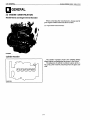
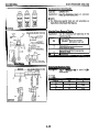
WORKSHOP MANUAL
DIESEL
ENGINE
MANUEL DNTELIER
MOTEUR
DIESEL
WERKSTAT TANLEITUNG
DIESELMOTOR
92.4mm STROKE SERIES
MOTEUR
DE
92.4mm
DE
COURSE
SERIENMOTOR
~
MIT
92.4mm
HUB
~ ~~
~


TO
THE
READER
This
Workshop Manual has been prepared to provide servicing personnel with
information on the mechanism, service and maintenance of KUBOTA Diesel
Engine
92.4
mm STROKE
SERIES.
It
is
divided into two parts, "Mechanism" and
"Disassembling and Servicing".
Mechanism
Information on construction and functions are included for each engine
section. This part should be understood before proceeding with trouble-
shooting, disassembling and servicing.
Disassembling and Servicing
Under the heading "General" come general precautions, troubleshooting,
lists of servicing specifications and periodic inspection items. For each engine
section, there are "Checking and Adjustment",
"
Disassembling and Assembling",
and ."Servicing" which cover procedures, precautions, factory specification and
allowable limits.
All the engines that have been manufactured
since
January of
1994
are clean
The mark [E]
in
the
WSM
refers to the said
clean
engine.
All information, illustrations and specifications contained in this manual are
based on the
latest
production information available at
the
time of publication.
The right
is
reserved to make changes
in
all
information
at
any time without
notice.
Due to covering many models of this manual, illustration or picture being used
have not been.specified as one model.
axhaust engines.
August
1991
@
KUBOTA
Corporation
1991

INTRODUCTION
Ce manuel d'atelier a 6th prepare pour permettre au personnel d'entretien de
disposer d'informations sur les mbcanismes, les entretiens
et
la
maintenance des
moteurs KUBOTA Diesel moteur de serie
A
92'4
mm de course.
I1
est divisk en
deux sections: "Mkcanismes"
et
"Demontage
et
entretien".
MBcanisrnes
Des informations sur la construction
et
les
fonctions sont donnees pour
chaque partie du moteur. Cette partie du manuel doit &re comprise avant que
I'oncommence les operations de recherche des anomalies, de dkmontage et
d'entretien.
H
DBmontage
et
entretien
Sous le titre "GCnBralitBs" on trouvera des precautions generales, les
procedures de recherche des anomalies et les Iistes de caracteristiques
d'entretien et items de vbrification periodique. Pour chaque partie du moteur,
on trouvera
les
titres "Verification et reglage", "DBmontage et remontage" et
"Entretien"
00
sont reprises
les
precautions,
les
caracteristiques d'usine et
les
limite de service.
Les moteurs fabriques depuids Janvier
1994
out et6 consus de fason b
Ces moteurs non polluants sont indiques dans
le
WSM
par la lettre
[E].
Toutes lees informations, illustrations et sp6cifications contenues dans ce
manuel sont basbes sur les dernihres informations de production disponibles au
moment de
la
publication. Nous nous rCservons le droit de modifier tout
element de
ces
infomations,
6
tout moment
et
sans prCavis.
Ce manuel couvrant de nombreux mod&les,
les
illustrations ou photos utilisees
sont donnbes
b
titre indicatif.
produire d'bchappement non polluants.
Aout
1991
@
KUBOTA
Corporation
1991

FUR
DEN
LESER
Dieses Handbuch sol1 dem Wartungspersonanl lnformationen uber die
Funktion, den Betrieb und die Wartung der KUBOTA-Dieselmotoren
Serienmotormit
92,4
mm
Hub liefern.
Es
ist
in
zwei Teile, "Funktion" und
"Ausbau und Wartung" aufgegliedert.
Mechanismus
Fur jeden Motorabschnitt werden lnformationen bezuglich Konstruktion und
Funktion gegeben. Dieser Teil sollte sorgfaltig gelesen werden, bevor mit der
Storungssuche, dem Ausbau und der Wartung begonnen wird.
Ausbau und Wartung
Der Abschnitt "allgemeines" beinhaltet allgemeine Vorkehrungen, Storungs-
suchen und Listen von Wartungsdaten sowie von regelmaBig zu uberprufenden
Teilen. Fur jeden Motorabschnitt
ist
ein Kapitel "Prufung und Einstellung",
"Aus- und Einbau" und "Wahung" vorgesehen, welches uber Verfahrensweisen,
Vorkehrungen, Werkdaten und zulassige Grenzwerte AufschluB gibt.
Alle Motoren, die ab Januar
1994
hergestellten werden sind Sauberab
Die Marke
[E]
bezieht
sich
auf den vorgenannten sauberen Motor.
M otoren.
Allen in diesem Hanbuch enthaltenen Informationen, Abbildungen und
technischen Merkmalen liegen die letzten, zum Zeitpunkt der Veroffentlichung
verfugbaren Informationen zugrunde. Eine Anderung aller lnformationen zu
jeder Zeit und ohne Ankundigung bleibt vorbehalten.
Da
in diesem Handbuch mehrere Modelle beschrieben werden, wurden die
jeweilig verwendeten abbildungen oder Bilder nicht fur ein einzelnes Modell
prazisiert.
August
1991
0
KUBOTA Corporation 1991

!

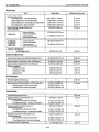
CONTENTS
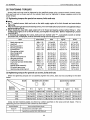
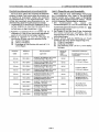
SAFETY INSTRUCTIONS
1
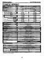
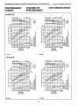
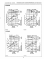
PERFORMANCE CURVES
18
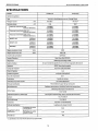
SPEC1 FlCATl ONS
12
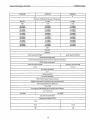
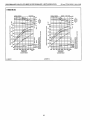
DIMENSIONS
21
I
M.
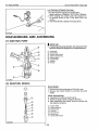
MECHANISM
I
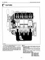
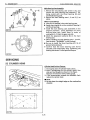
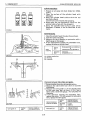
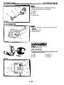
F. FEATURE
M-1
1.
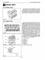
ENGINE BODY M-3
[I]
CYLINDER BLOCK
M-3
[2] CYLINDER HEAD M-3
[31
CRANK
SHAFT
M-5
[5] CONNECTING ROD M-5
[6] CAMSHAFT M-7
171
FLYWHEEL
M-7
[8] ROCKER
ARM
M-7
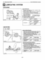
2. LUBRICATING SYSTEM M-9
[I]
GENERAL M-9
[2] OIL PUMP M-11
131
RELIEF
VALVE
M-11
[41
OIL
FILTER
CARTRIDGE
M-13
151
OIL
PRESSURE
SWITCH
M-13
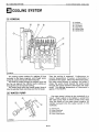
3. COOLING SYSTEM M-15
[I]
GENERAL M-15
..................................
....................................
.......................................
[4] PISTON AND PISTON RINGS
...................
M-5
.................................
............................................
.............................................
.........................................
...............................................
............................................
......................................
.........................
.........................
.............................................
......................................
[2] WATER PUMP
M-15
131 THERMOSTAT
M-17
[41
RADIATOR
M-17
[5] RADIATOR CAP
;........
M-17
4.
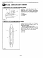
INTAKE/EXHAUST SYSTEM M-19
[I]
AIR
CLEANER M-19
[2] MUFFLER M-19
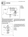
5. FUEL SYSTEM M-21
[I]
GENERAL M-2 1
[2] INJECTION PUMP M-2 1
[4] FUEL FILTER M-27
[5] FUEL LIFT PUMP M-29
[6] GOVERNOR M-3 1
6.
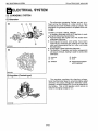
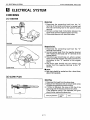
ELECTRICAL SYSTEM M-35
[I]
CHARGING,SYSTEM M-35
......................................
...........................................
....
.......................
.......................................
.............................................
.............................................
.................................
[31
INJECTION
NOZZLE
..............................
M-27
.........................................
...................................
.........................................
.............................
S.
DISASSEMBLING AND SERVICING
I
I
G. GENERAL
s-1
[l]
ENGINE IDENTIFICATION
s-
1
[2] GENERAL PRECAUTlONS 5-3
[3] TIGHTENING TORQUES
5-5
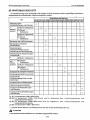
[5] SERVICING SPECIFICATIONS
..................
5-1 6
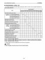
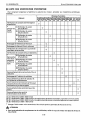
[6] MAINTENANCE CHECK LIST
..................
5-32
[7] CHECK AND MAINTENANCE
.................
s-35
[8] SPECIALTOOLS s-45
1.
ENGINE BODY s-53
CHECKING AND ADJUSTING 5-53
D
ISASSEM
B
LING AN D
ASS
EM
B
LI
N
G
e-.
--.
- -
-*-.
s-55
[l]
DRAINING WATER AND OIL
..................
5-55
[2] EXTERNAL COMPORNENTS
...................
5-55
[3] CYLINDER HEAD AND VALVES
..............
5-57
[41
GEAR
CASE
5-59
[5] PISTON AND CONNECTING ROD
............
5-67
[6] FLYWHEEL AND CRANKSHAFT
*-*-----------
S-71
s
E
RVI
CI
N
G
s-73
[I]
CYLINDER HEAD 5-73
[2] TIMING GEARAND CAMSHAFT............. 5-81
[3] PISTON AND CONNECTING ROD
............
S-85
[4]
CRANKSHAFT 5-89
[51
CYLINDER
BORE
5-98
2. LUBRICATING SYSTEM s-99
CHECKING s-99
........................
.........................
...........................
...............................
14.1
TROUBLESHOOTlNG 5-8
.....................................
........................
............................................
...................................................
....................................
........................................
...................................
.................................................
.................................................
SERVICING s-99
[I]
OIL PUMP 5-99
3. COOLING SYSTEM
5-101
CHECKING 5-1 01
[I]
FAN BELT 5-1 01
[2] RADIATOR 5-101
............................................
................................................
............................................
..........................................
DISASSEMBLING AND ASSEMBLING **-.------ S-103
4.
FUEL SYSTEM S-105
CHECKING AND ADJUSTING 5-1 05
[I]
INJECTION PUMP S-105
[2] INJECTION NOZZLE S-107
DISASSEMBLING AND ASSEMBLING
..........
5-109
[I]
INJECTION PUMP s-109
[2] INJECTION NOZZLE 5-1 09
5. ELECTRICAL SYSTEM
s-111
CHECKING 5-1 11
[I]
STARTER s-111
[2] GLOW PLUG
s-11
1
[3] ALTERNATOR AND REGULATOR
..........
5-1 13
DISASSEMBLING AND ASSEMBLING
..........
S-123
[I]
STARTER 5-1 23
[2] ALTERNATOR 5-125
SERVICING 5-133
[I]
STARTER S-133
[2] ALTERNATOR 5-1
37
......................
................................
.............................
................................
.............................
.................................................
.............................................
........................................
.............................................
......................................
................................................
.............................................
......................................

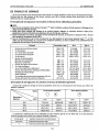
TABLE
DES
INSTRUCTIONS DE SECURITE 4 COURBES DE PERFORMANCE
18
SPECEFICATIONS 14 DIMENSIONS
21
M.
MECANISME
F.
GENERALITES M-2
1.
CORPS DU MOTEUR M-4
[I]
BLOC-MOTEUR M-4
[2]
CULASSE M-4
[3] VlLEBREQUlN M-6
[41
PISTON
ET
SEGMENTS
M-6
151
B~ELLE
M-6
[6]
ARBRE
A
CAMES ET CAME DE POMPE
D’ALIMENTATION M-8
[’/I
VOLANT M-8
[e]
CULBUTEURS M-8
2.
SYSTEME DE LUBRIFICATION M-9
[I]
GENERALlTES M-9
[2] POMPE A HUlLE M-12
[4]
CARTOUCHE DE FILTREA HUILE
----*-.---
M-14
[5]
MANOCONTACT DE PRESSION
D‘HUJLE M-14
......................................
................................................
........................................
...........................
...................................................
.................................
................................................
..........................................
........................................
...................................
[3] SOUPAPE DE DECHARGE
.....................
M-12
...............................................
3.
SYSTEME DE REFROIDISSEMENT
M-I
6
[I]
GENERALlTES M-16
[2] POMPE A EAU M-16
[3] THERMOSTAT M-18
[4] RADlATEUR M-18
4. ADMISSION ET ECHAPPEMENT
M-20
213 FILTRE
AAlR
M-20
[2] POT D’ECHAPPEMENT M-20
5. SYSTEME D’ALIMENTATION M-22
[I] GENERALITES M-22
[2]
POMPE D’INJECTION M-22
[3] INJECTEURS M-28
[41
FILTRE
A
CARBURANT
M-28
[5] POMPE D’ALIMENTATION M-30
[6] REGUMTEUR M-32
6. SYSTEME ELECTRIQUE M-36
[I]
ClRCUIT DE CHARGE M-36
......................................
.....................................
.....................................
.........................................
[5] BOUCHON DU RADIATEUR
..................
M-18
........................................
.........................
.......................................
............................
.........................................
.........................
..................
......................................
............................
S.
DEMONTAGE ET ENTRETIEN
G.
GENERALITES
s-2
[l]
IDENTIFICATION DU MOTEUR
.................
5-2
[2] PRECAUTIONS GENERALITES
-****.*.*.*-*--.-*
5-4
[31
COUPLES
DE
SERRAGE
S-6
[41
DEPANNAGE
s-10
[SI
CARACTERISTIQUES D’ENTRETIEN
---**-*.
5-22
D’ENTRETIEN 5-33
[7] VERIFICATION ET ENTRETIEN
--*..***..-.***
S-36
[8] OUTlLS SPEClAUX
.................................
S-46
1.
CORPS DU MOTEUR s-54
DEMONTAGE ET MONTAGE
.......................
S-56
[I]
VIDANGE D‘EAU ET D’HUILE
.................
S-56
[2] COMPOSANTES EXTERNES
...................
5-56
[4]
CARTER DE DISTRIBUTION .................... S-60
[51
PISTON
ET
B~ELLE
.................................
S-68
[6] VOLANT ET VlLEBREQUlN
.....................
S-72
ENTRETlEN 5-74
[I]
CU
MSSE
s-74
[2] PIGNON DE DISTRIBUTION
ETARBRE A CAMES
...............................
5-82
[3] PISTON ET BlELLE
..................................
S-86
[41
VILEBREQUIN
s-90
............................
.........................................
[6] LISTE DES VERIFICATION
........................................
VERlFlCATlON ET REGLAGE
........................
5-54
[3] CULASSE ETSOUPAPES
.........................
5-58
..................................................
...............................................
........................................
[5] CHEMISE DE CYLINDRE
.......................
5-98-1
2.
SYSTEME
DE
LUBRIFICATION
s-100
VERlFlCATlON
s-100
ENTRETlEN s-1
00
[I]
POMPE
A
HUlLE
s-1
00
3.
SYSTEME DE REFROIDISSEMENT
s-I02
VERI
FI
CAT1 ON s-102
[l]
COURROIE DE VENTILATEUR
.--***-*---.*.
s-102
[2] RADlATEUR 5-1
02
DEMONTAGE ET MONTAGE
5-
104
4.
SYSTEME D’ALIMENTATION S-106
VERlFlCATlON ET REGLAGE
......................
S-106
[I]
POMPE D’INJECTION S-106
[2] INJECTEU
R
5-1 08
DEMONTAGE ET MONTAGE
5-1
10
[I] POMPE D’INJECTION s-110
[2] INJECTEUR s-110
5.
SYSTEME ELECTRIQUE
5-112
VERI
F
I
CAT1
0
N
s-112
s-112
[I] DEMARREUR
......................
i................
[2]
BOUGIE DE PRECHAUFFAGE ............... s-112
[3] ALTERNATEUR ET REGULATEUR
.........
S-114
...........................................
...............................................
..................................
...........................................
.........................................
.....................
..........................
..........................................
.....................
..........................
..........................................
...........................................
......................
DEMONTAGE ET MONTAGE S-124
[I]
DEMARREUR 5-1 24
[2] ALTERNATEU
R
S-126
ENTRETlEN
5-
134
[I] DEMARREUR
.......................................
S-134
[2] ALTERNATEUR S-138
.......................................
....................................
................................................
....................................

SICHERHEITSMASSNAHMEN
8
LEI STU NGSKU RVEN
18
TECH NlSCH
E
MERKMALE 16 ABMESSUNGEN 21
M.
MECHANISMUS
F.
ALLGEMEINES M-2
I.
MOTORKORPER M-4
[I]
ZYLlNDERBLOCK
M-4
[2] ZYLlNDERKOPF
M-4
[3] KURBELWELLE M-6
[51
PLEUELSTANGE
M-6
[6] NOCKENWELLE M-8
[71
SCHWUNGRAD
M-8
[8] KlPPHEBEL NI-8
2. SCHMIERUNGSSYSTEM M-9
[I]
ALLGEMEINES
M-9
[2] OLPUMPE M-12
[3]
~BERDRUCKVENT~L
M-12
[4]
(~LF~LTERPATRONE
M-14
[5] OLDRUCKSCHALTER M-14
3. KUHLUNGSSYSTEM
M-I
6
...................................
.....................................
......................................
[4] KOLBEN UND KOLBENRINE
...................
M-6
.....................................
.....................................
......................................
..............................................
.......................................
............................................
............................
..............................
............................
.....................................
[I]
ALLGEMElNES M-16
[2] WASSERPUMPE M-16
[31
THERMOSTAT M-18
141
K~HLER
M-18
[SI
KOHLERVERSCHLUSSKAPPE
M-18
4.
ANSAUG- UND AUSPUFFSYSTEM M-20
[I]
LUFTFlLTER M-20
[2] AUSPUFFTOPF M-20
5. KRAFTSTOFFSYSTEM M-22
[I]
ALLGEMlNES M-22
[2] ElNSPRlTZPUMPE M-22
[3]
E~NSPRITZD&E
M-28
[4]
KRAFTSTOFFFlLTER M-28
[SI
KRAFTSTOFF-F~RDERPUMPE
M-30
[6] DREHZAHLREGLER M-32
6. ELEKTRISCHESSYSTEM M-36
[I]
LADESYSTEM M-36
...................................
.....................................
...............................................
................
..........................................
.....................................
.......................................
................................
...................................
.............................
..............
..............................
......................................
S.
AUSBAU UND WARTUNG
G.
ALLGEMEINES s-2
[l]
MOTOR KENNZEICHNUNG 5-2
[2] ALLGEMEINES VORKEHRUNGEN
............
5-4
[3] ANZUGSDREHMOMENTE 5-7
[6] WARTUNGS-CHECKLlSTE 5-34
[71
OBERPROFUNG
UND
WARTUNG
...........
S-36
[8] SPEZlALWERKZEIJGE 5-46
I.
MOTORKORPER s-54
OBERPRUFUNG UND EINSTELLUNG
.............
5-54
AUS- UND EINBAU S-56
[l]
ABLASSEN VON WASSER UND OL......... S-56
[2]
AUssERE BAIJTElLE 5-56
[3]
ZYLINDERKOPF UNDVENTILE
..............
5-58
[4]
GETR~EBEGEHAUSE 5-60
[5] KOLBEN UND PLEUELSTANGE
..............
5-68
[6] SCHWUNGRAD UND KURBELWELLE
..---
5-72
WARTU NG
..................................................
5-74
[I]
ZYLlNDERKOPF 5-74
[2] STEUERUNG UND NOCKENWELLE
........
5-82
[3] KOLBEN UND PLEUELSTANGE
...............
5-86
[41
KURBELWELLE
5-90
151
ZYL~NDERMUFBUCHSE
.......................
S-98- 1
2. SCH MIERUNGSSY STEM 5-100
UBERPR~FUNG
5-1
00
.....................
.......................
.................................
[4]
ST~RUNGSSUCHE
S-13
[51
WARTUNGSDATEN
S-27
...............................
......................
............................
......................................
..............................
...............................
.....................................
......................................
.........................................
................................................
WARTUNG
s-1
00
...........................................
[I]
(~LPUMPE
5-1
00
3.
KU
HLUNGSSYSTEM
s-I
02
~BERPROFUNG
s-102
[I]
LUFTERRlEMEN 5-1 02
[2]
KOHLER
5-102
AUS- UND ElNBAU
S-
1 04
4.
KRAFTSTOFFSYSTEM S-106
OBERPROFUNG UND EINSTELLUNG
..........
5-1
06
[I]
ElNSPRlTZPUMPE 5-1
06
121
E~NSPR]TZD(~SE
S-108
AUS- UND ElNBAU s-110
[I]
ElNSPRlTZPUMPE 5-1 10
[2]
E~NSPR~TZD~SE
5-1
10
5. ELEKTRISCHESSYSTEM s-I 12
(~BERPR~FUNG
5-1
12
[I]
ANLASSER s-112
[2]
GLOHKERZE
5-1 12
[3]
.........................................
..................................
..............................................
....................................
................................
...................................
.....................................
................................
...................................
.........................................
...........................................
........................................
LICHTMASCHINE UND REGLER
............
S-114
AUS- UND ElNBAU
5-1
24
[I]
ANLASSER 5-124
[2] LlCHTMASCHlNE 5-126
WARTUNG S-134
[I]
ANMSSER 5-1 34
[2]
LlCHTMASCHlNE S-138
.....................................
...........................................
.................................
................................................
...........................................
.................................


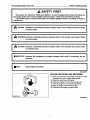
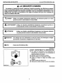
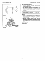
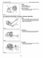
ASAFETY
FIRST
I
JOOOOFOOO1O
-
I
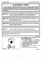
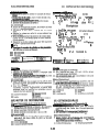
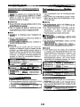
DANGER :Indicates an imminently hazardous situation which, if not avoided, will result
in
death
or serious injury.
A
WARNING: Indicates a potentially hazardous situation which, if not avoided, could result
in
death
or serious injury.
I
CAUTION :Indicates a potentially hazardous situation which, if not avoided, may result
in
minor
or moderate injury.
I"
I
IMPORTANT :Indicates that equipment or property damage could result if instructions are not
followed.
I
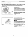
NOTE :Gives helpful information.
ooooozooo77
BEFORE
SERVICING
AND REPAIRING
(1)
Read all instructions and safety instructions in this
manual and on your engine safety decals.
(2) Clean the work area and engine.
(3)
Place the engine on
a
firm and level ground.
(4)
allow the engine to cool before proceeding.
(5)
Stop the engine, and remove the key.
(6)
Disconnect the battery negative cable.
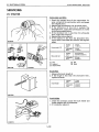
00000200021

SAFETY
INSTRUCTIONS
92.4
mm
STROKE
SERIES
WSM,
01wA
ml
SAFETY STARTING
(1)
Do
not start the engine by shorting across starter
terminals.
(2)
Unauthorized modifications to the engine may impair
the function and
/
or
safety and affect engine life.
I
00000Z00031
~00000F00021
oooO0F00030
I
r
l
z
I
10000F00050
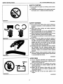
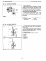
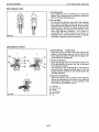
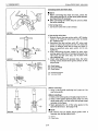
SAFETY WORKING
(1)
Do
not work on the engine while under the influence
of alcohol, medication, or other substances or while
fatigued.
(2)
Wear close fitting clothing and safety equipment
appropriate to the job.
(3)
Use tools appropriate to the work. Makeshift tools,
parts, and procedures are not recommended.
(4)
When servicing is performed together by
two
or more
persons, take care to perform all work safely.
(5)
Do
not touch the rotating or hot parts while the engine
is running.
(6)
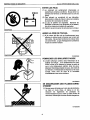
Never remove the radiator cap while the engine is
running, or immediately after stopping. Otherwise,
hot water will spout out from radiator. Only remove
radiator cap when cool enough to touch with bare
hands. Slowly loosen the cap to first stop to relieve
pressure before removing completely.
(7) Escaping fluid (fuel or hydraulic oil) under pressure
can penetrate the skin causing serious injury.
Relieve pressure before disconnecting hydraulic or
fuel lines. Tighten all connections before applying
pressure.
(8)
Wear
a
suitable hearing protective device such as
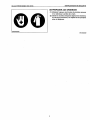
earmuffs or earplugs to protect against objectionable
or
uncomfortable loud noises.
00000200041
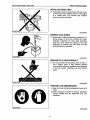
l
AVOID FIRES
(1)
Fuel is extremely flammable and explosive under
certain conditions.
Do
not smoke
or
allow flames or
sparks in your working area.
(2) To avoid sparks from an accidental short circuit,
always disconnect the battery negative cable first
and connect
it
last.
(3)
Battery gas can explode. Keep sparks and open
flame away from the top of battery, especially when
charging the battery.
(4) Make sure that
no
fuel has been spilled on the
engine.
OOOOOZ00050
2

924
rnm
STROKE
SERIES
VdSkI,
01
WA
SAFRy
INSTRUCTIONS
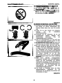
VENTILATE
WORK
AREA
(I)
If
the engine must be running to do some work, make
sure the area
is
well ventilated. Never run the engine
in
a closed area. The exhaust gas contains
poisonous carbon monoxide.
80
ooomzmMo
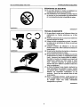
PREVENT ACID BURNS
(1)
Sulfuric acid in battery electrolyte is poisonous.
It
is
strong enough to burn skin, clothing and cause
blindness if splashed into eyes. Keep electrolyte
away from eyes, hands and clothing. If you spill
electrolyte on yourself, flush with water, and get
medical attention immediately.
00000Z00070
DISPOSE OF FLUIDS PROPERLY
(1)
Do
not pour fluids into the ground, down
a
drain, or
into a stream, pond, or lake. Observe relevant
environmental protection regulations when disposing
of oil, fuel, coolant, electrolyte and other harmful
waste.
00000200080
PREPARE FOR EMERGENCIES
(1)
Keep a first aid kit and fire extinguisher handy at all
times.
(2)
Keep emergency numbers for doctors, ambulance
service, hospital and fire department near your
telephone.
3

INSTRUCTIONS
DE
SECURITE
92.4
mm
STROKE
SERIES
WSM,
0109A
1
A
LA
SECURITE
D’ABORD
I
~
\
DANGER
:
lndique une situation eminemment dangereuse, des blessures graves
ou
la mort
peuvent survenir si cette situation n’est pas bvitbe.
I
I
AVERTISSEMENT
:
lndique une situation potentiellement dangereuse, des blessures graves
ou
la mort peuvent survenir si cette situation n’est pas evitbe.
I
:
lndique une situation potentlellement dangereuse, des blessures mineures
ou
graves peuvent survenir si cette situation n’est pas evitbe.
I
aArrENTloN
I
IMPORTANT
:
Ceci lndique que
si
les
instructions
ne
sont pas suivies, des dommages
ou
dbgats
peuvent &re occasionnes
21
1’6quipement
ou
A
des biens.
I
NOTA
:Donne des informations utlles.
I
0000020001
IF
AVANT L’ENTRETIEN
ET
LA
REPARATION
(1)
Lire toutes les instructions et les instructions de
securite dans ce manuel et
sur
les autocollants de
s6curit6 accol6s
sur le moteur.
(2)
Nettoyer la zone
du
travail et le moteur.
(3)
Placer le moteur
sur
un
sol
ferme
21
niveau.
(4)
hisser au moteur le temps de refroidir avant
d’operer.
(5)
Arreter le moteur et retirer la
cl6.
(6)
Debrancher le cable
de
mise
h
la terre de la batterie.
00008Z00021
F
4

924rnm
STROKE
SERIES
WS!d,
91WA
INSTRUCTIONS
DE
SECURlTE
.
JOOOOF00021
I
I
I
~00000F00030
I
DEMARRAGE
DE
SECURlTE
(1)
Ne pas faire demarrer le moteur en etablissant
un
courtcjrcuit entre les bornes du d6marreur.
(2)
Des modifications non autorisees au moteur reiquent
de diminuer
ou
de compromettre le fonctionnement
et
/
ou
la
securite ainsi que la durabilite du moteur.
00000Z00031F
TRAVAIL EN SECURITE
(1)
Ne pas utiliser le moteur
sous
I’influence d’alcool, de
medicaments
ou
d’autres substances
ou
a
I’etat
fatique.
(2)
Porter des vetements pres du corps et du materiel de
securite approprie au travail.
(3)
Utiliser les outils correspondant au travail. Les outils,
les pieces et les procedures de fortune ne sont pas
recommandes.
(4)
Lorsqu’un entretien est effectuee
a
la fois par
plusieurs personnes, veiller
a
executer les travaux en
toute securite.
(5) Ne pas toucher les pieces tournantes
ou
chaudes au
cours du fonctionnement du moteur.
(6)
Ne pas enlever le bouchon de radiateur au cours du
fonctionnement du moteur
ou
immediatement apres
I’arret. Autrement I’eau chaude jaillira du radiateur.
Ne retirer
le
bouchon de radiateur que lorsqu’il est
suffisamment refroidit pour Qtre touche
a
mains
nues. Desserrer lentement le bouchon jusqu’au
premier arret pour relscher la pression avant de la
retirer completement.
(7) Le fluide s’echappant
sous
pression (carburant
ou
huile hydraulique) peut penetrer la peau, causant
une blessure grave. Detendre la pression avant de
detacher les tuyauteries hydrauliques
ou
de
carburant. Serrer tous les raccords avant la mise
sous
pression.
(8)
Porter un dispositif protecteur auditif approprie tel
qu’un protege-oreilles
ou
un protege-tympans pour
se proteger contre des bruits retentissants
desagreables
ou
gQnants.
OOOOOZOOO4
I
F
5

INSTRUCTIONS DE SECURITE
92.4
rnrn
STROKE
SERIES
WSM,
01
09A
EVITER LES FEUX
(1)
Le carburant est extrdmement inflammable et
..
explosif dans certaines conditions. Ne pas fumer
ou
admettre les flammes
ou
btincelles dans la zone de
t
ravai
I.
(2)
Pour prevenir un courtqircuit dQ aux 6tincelles,
deconnecter le cable de mise
a
la terre de la batterie
le premier et le connecter le dernier.
(3)
Le gaz de batterie est explosible. Maintenir les
etincelles et flammes nues eloignees de
la
batterie,
lors de la charge de la batterie en particulier.
(4) Veiller
a
ne pas renverser de carburant sur le moteur.
AERER
LA
ZONE
DE
TRAVAIL
(1)
Si le moteur doit dtre mis en fonctionnement pour
effectuer le mdme travail, s’assurer que la zone est
bien aeree. Ne pas faire fonctionner le moteur dans
une zone fermee. Le gaz d’echappement contient de
I’oxyde de carbone toxique.
oooO0F00050
11910Z00050
11910z00060
PEMPECHER LES BRULURES D’ACIDE
(1)
L‘acide sulfurique contenu dans I’electrolyte de la
batterie est toxique.
II
est suffisamment fort pour
brQler la peau et le vdtement et causer la perte de
vue si une Bclaboussure pBn6tre dans les yeux.
Maintenir I’Blectrolyte Bloigne des yeux, des mains et
du vdtement. Si I’electrolyte est repandu sur le corps
humain, rincer avec de I’eau et le soumettre
immediatement aux soins mBdicaux.
1191ozm70
SE DEBARRASSER DES FLUIDES CORRE-
CTEMENT
(1)
Ne pas verser de fluides sur le
sol,
dans la plomberie,
ou
dans un cours d’eau, un Btang
ou
un lac.
Observer les rbglements de protection de
I’environnement lors de la mise
au
rebut d‘huile, de
carburant, d’electrolyte et autres dechets dangereux.
6

92.4
mm
m0KE
SERIES
WSM,
0109A
INSTRUCTIONS
DE
SECURITE
SE
PREPARER
AUX
URGENCES
(I)
Maintenir toujours
une
trousse
de
premiers secours
et
un
extincteur
a
pottee
de
la
main.
(2)
Garder
le
nurneros d‘appel d’urgence des docteurs,
du
service d‘arnbulance,
de
I’hhpital
et
des
pornpiers
pres
do
telephone.
11910z00090
7

SICHERHEIT
ZUERST
92.4
rnrn
STROKE
SERIES
WSM,
0109A
I
ANMERKUNG
:
Nutzliche Zusatzinformationen.
i
.....................................................................................................................................
%
B
A
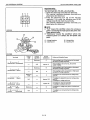
SICHERHEIT ZUERST
1
1
Dieses branchenubliche “Sicherheitswarnsymbol” dient
in
der vorliegenden Werkstattanleitung
I
GEFAHR
:
Dieses Zeichen weist auf die Mogllchkeit einer auBerst gefahrlichen Situation
hin
die
zu
einem schweren Unfall fiihren kann, wenn sie nicht vermieden wird.
A
WARNUNG
:
Dieses Zeichen warnt davor, keine gefahrlichen Situationen einzugehen, die zu
schweren Unfallen fuhren konnen.
A
VORSICHT
:
Dieses Zekhen macht Sie darauf aufmerksam, dal3 es durch unaufmerksames
Verhalten
zu
Unfallen kommen kann.
WlCHTlG
:
Hinweis auf mogliche Sachschaden bei Nichtbefolgung der Anweisungen.
OoooO20Dool1
D
VOR BEGINN DER WARTUNGS- UND
REPARATURARBEITEN
(1)
Lesen Sie alle Anweisungen und Vorsichtshinweise
in diesem Handbuch und auf den
Sicherheitsaufklebern des Motors sorgfaltig durch.
(2)
Reinigen Sie den Arbeitsbereich und das Motor.
(3)
Den Motor auf festem und ebenem Boden ab.
(4) Den Motor abkuhlen lassen.
(5)
Stellen Sie den Motor ab und ziehen Sie den
(6)
Klemmen Sie das Minuskabel der Batterie
ab.
Zundschlussel ab,
000002000021D
8

924
mm
STROKE
SERIES
WSM,
0109A
SICHERHEIT ZUERST
)OOOOF00021
00000F00030
SICHERHEITSHINWEISE
ZUM
ANLASSEN
(1)
Das Fahrzeug niemals durch KurzschlieBen der
Anlasserklemmen.
(2)
Unzulrassige Veranderrungen am Motor k6nnen die
Funktion und
/
oder Sicherheit beeintrachtigen und
die Lebensdauer des Motors reduzieren.
0000020000310
SICHERHEITSHINWEISE
ZUM
BETRIEB
(1)
Verwenden Sie den Motor niemals, wenn Sie unter
dem EinfluB von Alkohol, Medikamenten oder
ahnlichen Mitteln stehen bzw. wenn Sie ermudet
sind.
(2)
Tragen Sie bei allen Arbeiten eng anliegende
Kleidung und die erforderliche
Sicherheitsausrustung.
(3)
Verwenden Sie nur Werkzeuge, die fijr die
auszufuhrenden Arbeiten geeignet sind.
BehelfsmaBige Werkzeuge,
.
Teile und
Arbeitsmethoden sind
zu
vermeiden..
(4)
Wenn die Wartungsarbeiten von zwei oder mehr
Personen gleichzeitig ausgefiihrt werden, ist stets
auf gegenseitige Sicherheit
zu
achten.
(5)
Bei laufendem Motor darauf achten, daB keine sich
drehenden oder noch heiBen Teile beruhrt werden.
(6)
Bei noch laufendem Motor oder
kurz
nach dem
Abstellen niemals den Kuhlerdeckel abnehmen, da
in diesem Fall heiBe Kuhlflussigkeit herausspritzt.
Der Kuhlerdeckel darf erst dann abgenommen
werden, nachdem sich der Motor soweit abgekuhlt
hat, daB er mit bloBen Handen beruhrt werden kann.
Den Deckel vorsichtig bis auf die erste
Einrastposition losen,
um evtl. noch vorhandenen
.
Druck abzulassen; danach den Deckel vollstandig
aufdrehen.
(7)
Unter Druck stehende, herausspritzende
Flussigkeiten (Kraftstoff oder Hydraulikflussigkeit)
konnen die Haut durchdringen und schwere
Verletzungen verursachen. Vor dem Abnehmen von
Hydraulik- oder Kraftstoffleitungen daher zuerst den
Druck ablassen. Vor dem Wiederanlegen des
Hydraulikdrucks sich vergewissern, daB alle
AnschluBnippel festgezogen sind.
(8)
Zum
Schutz vor ubermaBig lauten und daher
gehorschadigenden Gerauschen ist ein
Gehorschutz, wie zum Beispiel Ohrenschutzer oder
Ohrenstopfen, zu tragen.
00000200041
D
0

SICHERHEIT ZUERST
92.4
mm
STROKE
SERIES
WSM,
0109A
10000F00050
VORSICHTSHINWEISE ZUR
BRANDGEFAHR
(1)
Kraftstoff ist extrem feuergefahrlich und unter
gewissen Bedingungen explosiv. Im Arbeitsbereich
daher nicht rauchen; offene Flammen und Funken
sind fernzuhalten.
(2)
Um Funkenbildung durch einen unbeabsichtigten
KurzschluO
zu
vermeiden, ist stets das Minuskabel
als erstes abzuklemmen und als letztes Kabel wieder
anzubringen.
(3)
Die von der Batterie abgegebenen Gase sind
explosiv. Funken und offene Flammen sind vom
oberen Bereich der Batterie fernzuhalten; dies ist
besonders beim Laden der Batterie
zu
beachten.
(4)
Sich vergewissern, daB kein verschutteter Kraftstoff
auf dem Motor befindet.
AUF AUSREICHENDE BELUFTUNG DES
ARBEITSBEREICH ACHTEN
(1)
Wenn der Motor tur Ausfuhrung von
Wartungsarbeiten laden muB, ist unbedingt auf
ausreichende Beluftung des Arbeitsbereichs
zu
achten. Den Motor niemals in einem geschlossenen
Raum iaufenlassen, da die Auspuffgase giftiges
Kohlenmonoxid enthalten.
1
199OZOOO50
1
1990Z00060
VERBRENNUNGSGEFAHRDURCHS~~URE
(1)
Die in der Batterie enthaltene Schwefelsaure ist giftig
und atzend. Bei Kontakt mit der Haut oder
Kleidungsstucken sind Verbrennungen die Folge;
wenn Elektrolyt in die Augen gelangt, kann dies
Blindheit verursachen. Darauf achten, daB die Saure
von den Augen, der Haut und der Kleidung
ferngehalten wird. Sollte Elektrolyt auf unbedeckte
Hautstellen gelangen, sofort mit Wasser abspulen
und arztliche Hilfe in Anspruch nehmen.
11990Z00070
10
La page est en cours de chargement...
La page est en cours de chargement...
La page est en cours de chargement...
La page est en cours de chargement...
La page est en cours de chargement...
La page est en cours de chargement...
La page est en cours de chargement...
La page est en cours de chargement...
La page est en cours de chargement...
La page est en cours de chargement...
La page est en cours de chargement...
La page est en cours de chargement...
La page est en cours de chargement...
La page est en cours de chargement...
La page est en cours de chargement...
La page est en cours de chargement...
La page est en cours de chargement...
La page est en cours de chargement...
La page est en cours de chargement...
La page est en cours de chargement...
La page est en cours de chargement...
La page est en cours de chargement...
La page est en cours de chargement...
La page est en cours de chargement...
La page est en cours de chargement...
La page est en cours de chargement...
La page est en cours de chargement...
La page est en cours de chargement...
La page est en cours de chargement...
La page est en cours de chargement...
La page est en cours de chargement...
La page est en cours de chargement...
La page est en cours de chargement...
La page est en cours de chargement...
La page est en cours de chargement...
La page est en cours de chargement...
La page est en cours de chargement...
La page est en cours de chargement...
La page est en cours de chargement...
La page est en cours de chargement...
La page est en cours de chargement...
La page est en cours de chargement...
La page est en cours de chargement...
La page est en cours de chargement...
La page est en cours de chargement...
La page est en cours de chargement...
La page est en cours de chargement...
La page est en cours de chargement...
La page est en cours de chargement...
La page est en cours de chargement...
La page est en cours de chargement...
La page est en cours de chargement...
La page est en cours de chargement...
La page est en cours de chargement...
La page est en cours de chargement...
La page est en cours de chargement...
La page est en cours de chargement...
La page est en cours de chargement...
La page est en cours de chargement...
La page est en cours de chargement...
La page est en cours de chargement...
La page est en cours de chargement...
La page est en cours de chargement...
La page est en cours de chargement...
La page est en cours de chargement...
La page est en cours de chargement...
La page est en cours de chargement...
La page est en cours de chargement...
La page est en cours de chargement...
La page est en cours de chargement...
La page est en cours de chargement...
La page est en cours de chargement...
La page est en cours de chargement...
La page est en cours de chargement...
La page est en cours de chargement...
La page est en cours de chargement...
La page est en cours de chargement...
La page est en cours de chargement...
La page est en cours de chargement...
La page est en cours de chargement...
La page est en cours de chargement...
La page est en cours de chargement...
La page est en cours de chargement...
La page est en cours de chargement...
La page est en cours de chargement...
La page est en cours de chargement...
La page est en cours de chargement...
La page est en cours de chargement...
La page est en cours de chargement...
La page est en cours de chargement...
La page est en cours de chargement...
La page est en cours de chargement...
La page est en cours de chargement...
La page est en cours de chargement...
La page est en cours de chargement...
La page est en cours de chargement...
La page est en cours de chargement...
La page est en cours de chargement...
La page est en cours de chargement...
La page est en cours de chargement...
La page est en cours de chargement...
La page est en cours de chargement...
La page est en cours de chargement...
La page est en cours de chargement...
La page est en cours de chargement...
La page est en cours de chargement...
La page est en cours de chargement...
La page est en cours de chargement...
La page est en cours de chargement...
La page est en cours de chargement...
La page est en cours de chargement...
La page est en cours de chargement...
La page est en cours de chargement...
La page est en cours de chargement...
La page est en cours de chargement...
La page est en cours de chargement...
La page est en cours de chargement...
La page est en cours de chargement...
La page est en cours de chargement...
La page est en cours de chargement...
La page est en cours de chargement...
La page est en cours de chargement...
La page est en cours de chargement...
La page est en cours de chargement...
La page est en cours de chargement...
La page est en cours de chargement...
La page est en cours de chargement...
La page est en cours de chargement...
La page est en cours de chargement...
La page est en cours de chargement...
La page est en cours de chargement...
La page est en cours de chargement...
La page est en cours de chargement...
La page est en cours de chargement...
La page est en cours de chargement...
La page est en cours de chargement...
La page est en cours de chargement...
La page est en cours de chargement...
La page est en cours de chargement...
La page est en cours de chargement...
La page est en cours de chargement...
La page est en cours de chargement...
La page est en cours de chargement...
La page est en cours de chargement...
La page est en cours de chargement...
La page est en cours de chargement...
La page est en cours de chargement...
La page est en cours de chargement...
La page est en cours de chargement...
La page est en cours de chargement...
La page est en cours de chargement...
La page est en cours de chargement...
La page est en cours de chargement...
La page est en cours de chargement...
La page est en cours de chargement...
La page est en cours de chargement...
La page est en cours de chargement...
La page est en cours de chargement...
La page est en cours de chargement...
La page est en cours de chargement...
La page est en cours de chargement...
La page est en cours de chargement...
La page est en cours de chargement...
La page est en cours de chargement...
La page est en cours de chargement...
La page est en cours de chargement...
La page est en cours de chargement...
La page est en cours de chargement...
La page est en cours de chargement...
La page est en cours de chargement...
La page est en cours de chargement...
La page est en cours de chargement...
La page est en cours de chargement...
La page est en cours de chargement...
La page est en cours de chargement...
La page est en cours de chargement...
La page est en cours de chargement...
La page est en cours de chargement...
La page est en cours de chargement...
La page est en cours de chargement...
La page est en cours de chargement...
La page est en cours de chargement...
La page est en cours de chargement...
La page est en cours de chargement...
La page est en cours de chargement...
La page est en cours de chargement...
La page est en cours de chargement...
La page est en cours de chargement...
La page est en cours de chargement...
La page est en cours de chargement...
La page est en cours de chargement...
La page est en cours de chargement...
La page est en cours de chargement...
La page est en cours de chargement...
La page est en cours de chargement...
La page est en cours de chargement...
-
 1
1
-
 2
2
-
 3
3
-
 4
4
-
 5
5
-
 6
6
-
 7
7
-
 8
8
-
 9
9
-
 10
10
-
 11
11
-
 12
12
-
 13
13
-
 14
14
-
 15
15
-
 16
16
-
 17
17
-
 18
18
-
 19
19
-
 20
20
-
 21
21
-
 22
22
-
 23
23
-
 24
24
-
 25
25
-
 26
26
-
 27
27
-
 28
28
-
 29
29
-
 30
30
-
 31
31
-
 32
32
-
 33
33
-
 34
34
-
 35
35
-
 36
36
-
 37
37
-
 38
38
-
 39
39
-
 40
40
-
 41
41
-
 42
42
-
 43
43
-
 44
44
-
 45
45
-
 46
46
-
 47
47
-
 48
48
-
 49
49
-
 50
50
-
 51
51
-
 52
52
-
 53
53
-
 54
54
-
 55
55
-
 56
56
-
 57
57
-
 58
58
-
 59
59
-
 60
60
-
 61
61
-
 62
62
-
 63
63
-
 64
64
-
 65
65
-
 66
66
-
 67
67
-
 68
68
-
 69
69
-
 70
70
-
 71
71
-
 72
72
-
 73
73
-
 74
74
-
 75
75
-
 76
76
-
 77
77
-
 78
78
-
 79
79
-
 80
80
-
 81
81
-
 82
82
-
 83
83
-
 84
84
-
 85
85
-
 86
86
-
 87
87
-
 88
88
-
 89
89
-
 90
90
-
 91
91
-
 92
92
-
 93
93
-
 94
94
-
 95
95
-
 96
96
-
 97
97
-
 98
98
-
 99
99
-
 100
100
-
 101
101
-
 102
102
-
 103
103
-
 104
104
-
 105
105
-
 106
106
-
 107
107
-
 108
108
-
 109
109
-
 110
110
-
 111
111
-
 112
112
-
 113
113
-
 114
114
-
 115
115
-
 116
116
-
 117
117
-
 118
118
-
 119
119
-
 120
120
-
 121
121
-
 122
122
-
 123
123
-
 124
124
-
 125
125
-
 126
126
-
 127
127
-
 128
128
-
 129
129
-
 130
130
-
 131
131
-
 132
132
-
 133
133
-
 134
134
-
 135
135
-
 136
136
-
 137
137
-
 138
138
-
 139
139
-
 140
140
-
 141
141
-
 142
142
-
 143
143
-
 144
144
-
 145
145
-
 146
146
-
 147
147
-
 148
148
-
 149
149
-
 150
150
-
 151
151
-
 152
152
-
 153
153
-
 154
154
-
 155
155
-
 156
156
-
 157
157
-
 158
158
-
 159
159
-
 160
160
-
 161
161
-
 162
162
-
 163
163
-
 164
164
-
 165
165
-
 166
166
-
 167
167
-
 168
168
-
 169
169
-
 170
170
-
 171
171
-
 172
172
-
 173
173
-
 174
174
-
 175
175
-
 176
176
-
 177
177
-
 178
178
-
 179
179
-
 180
180
-
 181
181
-
 182
182
-
 183
183
-
 184
184
-
 185
185
-
 186
186
-
 187
187
-
 188
188
-
 189
189
-
 190
190
-
 191
191
-
 192
192
-
 193
193
-
 194
194
-
 195
195
-
 196
196
-
 197
197
-
 198
198
-
 199
199
-
 200
200
-
 201
201
-
 202
202
-
 203
203
-
 204
204
-
 205
205
-
 206
206
-
 207
207
-
 208
208
-
 209
209
-
 210
210
-
 211
211
-
 212
212
-
 213
213
-
 214
214
-
 215
215
-
 216
216


dans d''autres langues
- English: Kubota 92.4 mm Stroke Series
- Deutsch: Kubota 92.4 mm Stroke Series
Documents connexes
Autres documents
-
Shimano SM-SL98 Service Instructions
-
All-Power APE7210 Manuel utilisateur
-
Power Fist 8242471 Le manuel du propriétaire
-
Yamaha F115A Manuel utilisateur
-
-
-
Maserati Indy 4.2, 4.7, 4.9 Le manuel du propriétaire
-
Ransomes LHAG001 Parts Manual
-
Husqvarna HVA WR 250 2006 Le manuel du propriétaire
-