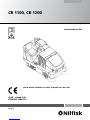
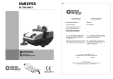
Nilfisk-Advance CR 1100 Instructions For Use Manual
- Catégorie
- Machine à plancher
- Taper
- Instructions For Use Manual
Ce manuel convient également à


ENGLISH / A-3
FORM NO. 56041776 - CR 1100, CR 1200 - A-3
TABLE OF CONTENTS
Page
Introduction ................................................................................... A-4
Parts and Service ........................................................................... A-4
Nameplate ...................................................................................... A-4
Uncrating the Machine .................................................................... A-4
Cautions and Warnings .................................................................. A-5
Consignes de prudence et de sécurité ........................................... A-6
General Information ........................................................................ A-7
Battery Installation ..................................................................A-8 - A-9
Know Your Machine / Operator’s Compartment .............. A-10 – 13
Preparing the Machine for Use
Pre-Operational Checklist ............................................................. A-14
Main Broom .................................................................................. A-14
Scrub Brush Installation ......................................................A-14 - A-15
Filling the Solution Tank ................................................................ A-16
Detergent (EDS) System ....................................................A-16 - A-17
Operating the Machine
Sweeping ...................................................................................... A-18
Emptying the Hopper .................................................................... A-18
Scrubbing ..................................................................................... A-19
Emptying the Recovery Tank ........................................................ A-19
After Using the Machine
After Use ....................................................................................... A-20
Maintenance Schedule
Maintenance Schedule ................................................................. A-20
Charging the Battery ..................................................................... A-21
Main Broom Maintenance ............................................................. A-22
Side Broom Maintenance ............................................................. A-23
Squeegee Maintenance ................................................................ A-24
Hopper Dust Control Filter ............................................................ A-25
Hydraulic Oil ................................................................................. A-25
Drive Wheel Gear Case Oil .......................................................... A-26
Lubrication .................................................................................... A-26
Circuit Breaker Location ............................................................... A-26
Troubleshooting ................................................................. A-27 – A-28
Technical Specifi cations ............................................................... A-29

A-4 / ENGLISH
A-4 - FORM NO. 56041776 - CR 1100, CR 1200
INTRODUCTION
This manual will help you get the most from your Nilfi sk™ Sweeper / Scrubber. Read it thoroughly before operating the machine. References to
“right” and “left” in this manual mean right or left as seen from the driver’s seat.
Note: Bold numbers or letters in parentheses indicate an item illustrated on pages 10 – 13 unless referred to a specifi c fi gure number.
PARTS AND SERVICE
Repairs, when required, should be performed by your Authorized Nilfi sk Service Center, who employs factory trained service personnel, and
maintains an inventory of Nilfi sk original replacement parts and accessories.
Call the NILFISK INDUSTRIAL DEALER named below for repairs or service. Please specify the Model and Serial Number when discussing your
machine.
(Dealer, affi x service sticker here.)
NAMEPLATE
The Model Number and Serial Number of your machine are shown on the Nameplate, located on the wall of the operator’s compartment. This
information is needed when ordering repair parts for the machine. Use the space below to note the Model Number and Serial Number of your
machine for future reference.
MODEL ________________________________________________
SERIAL NUMBER _______________________________________
Note: Reference the separately supplied engine manufacture’s maintenance and operator manual for more detailed engine specifi cation and
service data.
UN-CRATING
Upon delivery, carefully inspect the shipping crate and the machine for damage. If damage is evident, save all parts of the shipping crate so that
they can be inspected by the trucking company that delivered the machine. Contact the trucking company immediately to fi le a freight damage
claim.
1 After removing the crate, remove the wooden blocks next to the wheels and any hold down straps.
2 Check the hydraulic oil level.
3 Read the instructions in the Preparing the Machine For Use section of this manual, then install the battery.
4 Place a ramp next to the front end of the pallet.
5 Read the instructions in the Operating Controls and Operating the Machine sections of this manual. Slowly drive the machine forward down
the ramp to the fl oor. Keep your foot lightly on the brake pedal until the machine is off the pallet.
CAUTION!
Use extreme CAUTION when operating this machine. Be certain that you are thoroughly familiar with all operating instructions before
using this machine. If you have any questions, contact your supervisor or your local Nilfi sk Industrial Dealer.
If the machine malfunctions, do not try to correct the problem unless your supervisor directs you to do so. Have a qualifi ed company
mechanic or an authorized Nilfi sk Dealer service person make any necessary corrections to the equipment.
Use extreme care when working on this machine. Loose clothing, long hair, and jewelry can get caught in moving parts. Turn the
Key Switch OFF and remove the key before servicing the machine. Use good common sense, practice good safety habits and pay
attention to the yellow decals on this machine.
Drive the machine slowly on inclines. The drive pedal will control machine speed while descending inclines. DO NOT turn the
machine on an incline; drive straight up or down.
The maximum rated incline for sweeping and scrubbing is 6°. The maximum rated incline during transport is 8°.

ENGLISH / A-5
FORM NO. 56041776 - CR 1100, CR 1200 - A-5
CAUTIONS AND WARNINGS
SYMBOLS
Nilfi sk uses the symbols below to signal potentially dangerous conditions. Always read this information carefully and take the
necessary steps to protect personnel and property.
DANGER!
Is used to warn of immediate hazards that will cause severe personal injury or death.
WARNING!
Is used to call attention to a situation that could cause severe personal injury.
CAUTION!
Is used to call attention to a situation that could cause minor personal injury or damage to the machine or other property.
Read all instructions before using.
GENERAL SAFETY INSTRUCTIONS
Specifi c Cautions and Warnings are included to warn you of potential danger of machine damage or bodily harm.
WARNING!
* This machine shall be used only by properly trained and authorized persons.
* While on ramps or inclines, avoid sudden stops when loaded. Avoid abrupt sharp turns. Use low speed down hills.
* Keep sparks, fl ame and smoking materials away from battery. Explosive gases are vented during normal operation.
* Charging the battery produces highly explosive hydrogen gas. Charge battery only in well-ventilated areas away from open
fl ame. Do not smoke while charging the battery.
* Remove all jewelry when working near electrical components.
* Turn the key switch off (O) and remove the key, before changing the brushes, and before opening any access panels.
* Never work under a machine without safety blocks or stands to support the machine.
* Do not dispense fl ammable cleaning agents, operate the machine on or near these agents, or operate in areas where
fl ammable liquids exist.
* Do not clean this machine with a pressure washer.
* Only use the brushes provided with the appliance or those specifi ed in the instruction manual. The use of other brushes may
impair safety.
CAUTION!
* This machine is not approved for use on public paths or roads.
* This machine is not suitable for picking up hazardous dust.
* Use care when using scarifi er discs and grinding stones. Nilfi sk will not be held responsible for any damage to fl oor surfaces
caused by scarifi ers or grinding stones.
* When operating this machine, ensure that third parties, particularly children, are not endangered.
* Before performing any service function, carefully read all instructions pertaining to that function.
* Do not leave the machine unattended without fi rst turning the key switch off (O), removing the key and applying the parking
brake.
* Turn the key switch off (O) before changing the brushes, and before opening any access panels.
* Take precautions to prevent hair, jewelry, or loose clothing from becoming caught in moving parts.
* Use caution when moving this machine in below freezing temperature conditions. Any water in the solution or recovery tanks or
in the hose lines could freeze.
* The battery must be removed from the machine before the machine is scrapped. The disposal of the battery should be safely
done in accordance with your local environmental regulations.
* Do not use on surfaces having a gradient exceeding that marked on the machine.
* All doors and covers are to be positioned as indicated in the instruction manual before using the machine.
SAVE THESE INSTRUCTIONS

A-6 / ENGLISH
A-6 - FORM NO. 56041776 - CR 1100, CR 1200
CONSIGNES DE PRUDENCE ET DE SÉCURITÉ
SYMBOLES
Les symboles reproduits ci-dessous sont utilisés pour attirer l’attention de l’opérateur sur des situations dangereuses. Il est donc conseillé de lire
attentivement ces indications et de prendre les mesures adéquates en vue de protéger le personnel et le matériel.
DANGER!
Ce symbole est utilisé pour mettre l’opérateur en garde contre les risques immédiats pouvant provoquer des dommages corporels graves, voire
entraîner la mort.
ATTENTION!
Ce symbole est utilisé pour attirer l’attention sur une situation susceptible d’entraîner des dommages corporels graves.
PRUDENCE!
Ce symbole est utilisé pour attirer l’attention de l’opérateur sur une situation qui pourrait entraîner des dommages corporels minimes, ou des
dommages à la machine ou à d’autres équipements.
Lire toutes les instructions avant d’utiliser l’appareil.
CONSIGNES GENERALES DE SECURITE
Les consignes spécifi ques de prudence et de sécurité mentionnées ici ont pour but de vous informer de la survenance de tout risque de
dommages matériels ou corporels.
ATTENTION!
* Cette machine ne pourra être utilisée que par du personnel parfaitement entraîné et dûment autorisé.
* Evitez les arrêts subits lorsque la machine est chargée et se trouve sur des rampes ou des plans inclinés. Evitez les virages serrés. Adoptez une
vitesse réduite lorsque la machine est en descente. Ne nettoyez que lorsque la machine monte la pente.
* Eloignez les batteries de toutes fl ammes, étincelles ou substance fumigène. Les gaz explosifs sont ventilés pendant le fonctionnement normal.
* De plus, du gaz hydrogène explosif s’échappe des batteries lorsqu’elles sont en charge. Ne procédez au chargement des batteries que dans une
zone bien ventilée, loin de toute fl amme. Ne fumez pas à proximité des batteries lorsqu’elles sont en charge.
* Otez tous vos bijoux lorsque vous travaillez à proximité de composants électriques.
* Positionnez la clé de contact sur off (O) et déconnectez les batteries avant de procéder à l’entretien des composants électriques.
* Ne travaillez jamais sous une machine sans y avoir placé, au préalable, des blocs de sécurité ou des étais destinés à soutenir la machine
* Ne déversez pas d’agents nettoyants infl ammables, ne faites pas fonctionner la machine à proximité de ces agents ou d’autres liquides
infl ammables.
* Ne nettoyez pas cette machine avec un nettoyeur à pression.
* Utilisez uniquement les brosses fournies avec l’appareil ou celles spécifi ées dans le manuel d’instructions. L’utilisation d’autres brosses peut mettre
la sécurité en péril.
PRUDENCE!
* Cette machine n’est pas conçue pour une utilisation sur les chemins ou voies publics.
* Cette machine n’est pas conçue pour le ramassage des poussières dangereuses.
* N’utilisez pas de disques de scarifi cateur ni de meules. Nilfi sk ne pourra en aucun cas être tenue pour responsable des dommages occasionnés à
vos sols par ce type d’équipement (vous risquez également d’endommager le système d’entraînement des brosses).
* Lors de l’utilisation de cette machine, assurez-vous que des tiers, et notamment des enfants, ne courent pas le moindre risque.
* Avant de procéder à toute opération d’entretien, veuillez lire attentivement toutes les instructions qui s’y rapportent.
* Ne laissez pas la machine sans surveillance sans avoir, au préalable, coupé le contact, enlevé la clé de contact (O) et tiré le frein à main.
* Positionnez la clé de contact sur off (O) avant de remplacer les brosses ou d’ouvrir tout panneau d’accès.
* Prenez toutes les mesures nécessaires pour éviter que les cheveux, les bijoux ou les vêtements amples ne soient entraînés dans les parties mobiles
de la machine.
* Faites attention lorsque vous déplacez cette machine dans un endroit où la température peut descendre sous 0°. Car l’eau contenue dans les
réservoirs de solution ou de récupération ou dans les conduites risquerait de geler et par là même d’endommager les valves et raccords de la
machine. Rincez avec un liquide de lave-glace.
* Prenez soin d’enlever les batteries de la machine avant de mettre cette dernière au rebut. Pour ce qui est de l’élimination des batteries, conformez-
vous aux réglementations locales en matière d’environnement.
* N’utilisez pas sur des surfaces dont la pente dépasse celle mentionnée sur la machine.
* Toutes les portes et couvercles doivent être dans la position mentionnée dans le manuel d’instruction avant de mettre la machine en service.
CONSERVEZ SOIGNEUSEMENT CES INSTRUCTIONS

ENGLISH / A-7
FORM NO. 56041776 - CR 1100, CR 1200 - A-7
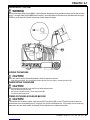
HOPPER SAFETY SUPPORT
WARNING!
Make sure the Hopper Safety Support (HH) is in place whenever attempting to do any maintenance work under or near the raised
hopper. The Hopper Safety Support (HH) holds the hopper in the raised position to allow work to be performed under the hopper.
NEVER rely on the machine’s hydraulic components to safely support the hopper.
JACKING THE MACHINE
CAUTION!
Never work under a machine without safety stands or blocks to support the machine.
• When jacking the machine, do so at designated locations (Do Not jack on the hopper) - see jacking locations (11)
TRANSPORTING THE MACHINE
CAUTION!
Before transporting the machine on an open truck or trailer, make sure that . . .
• All access doors are latched securely.
• The machine is tied down securely - see tie-down locations (4).
• The machine parking brake is set.
TOWING OR PUSHING A DISABLED MACHINE
CAUTION!
If the machine must be towed or pushed, make sure the Main Power Switch (CC) is in the OFF position and do not move the
machine faster than a normal walking pace (2-3 miles per hour) and for short distances only. If the machine is to be moved long
distances the rear drive wheel needs to be raised off the fl oor and placed on a suitable transport dolly.

A-8 / ENGLISH
A-8 - FORM NO. 56041776 - CR 1100, CR 1200
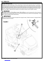
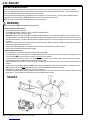
BATTERY INSTALLATION
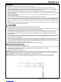
See Figure 1 & 2. The battery required for this machine is sold separately. The maximum battery weight for this machine is 1,875 lbs (850 kg);
the minimum battery weight is 1,400 lbs (635kg). For proper battery installation, please consult your Nilfi sk Industrial Dealer. DO NOT attempt
to install the battery with an overhead hoist or forklift; it can only be installed with a battery cart. Connect the connector plug (A) on the battery to
the machine plug behind the steering wheel. Make sure the battery is fi rmly seated against the End Brace (B) on the driver’s side of the battery
compartment. Reinstall the battery Stop Plate (C) on the left side of the compartment and snug up the Bumpers (D) so the battery cannot slide
from side-to-side. NOTE: The Battery Disconnect Tab (E) has to be assembled to the Battery Connector Plug (A) on the battery.
WARNING!
Battery weight in excess of 1,875 lbs (850 kg) or below 1,400 lbs (635kg) may cause the premature failure of parts including the
tires, and may result in decreased stability and control, which could cause personal injury or death and/or property damage. Use of a
battery in excess of the weight limit will void the warranty.
IMPORTANT!
Follow instructions packed with the battery and charger before charging the battery. Read the instructions for Charging the Battery in
the Maintenance section of this manual.
FIGURE 1


A-10 / ENGLISH
A-10 - FORM NO. 56041776 - CR 1100, CR 1200
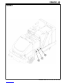
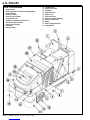
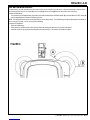
KNOW YOUR MACHINE
1 Operator’s Seat
2 Strobe Light (optional / standard on Nilfi sk Models)
3 Solution Tank Fill
4 Tie Down Locations
5 Recovery Tank Drain Hose
6 Recovery Tank Latch
7 Left Battery Compartment Access Panel
8 Main Broom Left Access Door
9 Hopper Cover Prop Rod
10 Front Wheel
11 Jacking Location
12 Left Side Broom
13 Hopper Cover Latch
14 Headlights
15 Right Side Broom
16 Hopper Cover
17 Dust Control Filter
18 Dust Control Shaker Assembly
19 Shaker Assembly Latch
20 Battery
21 Battery Compartment Door
22 Steering Wheel

ENGLISH / A-11
FORM NO. 56041776 - CR 1100, CR 1200 - A-11
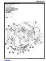
KNOW YOUR MACHINE (CONTINUED)
23 Electrical Compartment Door
24 Water Level Gauge
25 Recovery Tank Lid
26 Recovery Tank “Tip-Out” Grip
27 Hydraulic Power Unit (Reservoir & Filter)
28 Right Battery Compartment Access Panel
29 Main Broom Right Access Door
30 Access Door Latch
31 Skirt Assembly
32 Inline Solution Filter
33 Solution Tank Drain Hose
34 Rear Roller Bumper
35 Squeegee Tool Handle
36 Squeegee Tool Assembly
37 Tail Light

A-12 / ENGLISH
A-12 - FORM NO. 56041776 - CR 1100, CR 1200
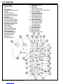
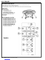
CONTROL PANEL
A Low Battery Indicator
B Horn
* Horn ON Indicator
C Parking Brake Indicator (not used)
D Headlights
* Headlight ON Indicator
E Machine Needs Service Indicator
F Hydraulic Filter Plugged Indicator
G Speed Switch
* Speed Switch Indicator
H Scrub Pressure Decrease Switch
* Scrub Pressure Decrease Indicator
I Scrub Pressure Increase Switch
* Scrub Pressure Increase Indicator
J Scrub Pressure Display
K Solution Switch
* Solution ON Indicator
L Solution Tank Empty Indicator
M Recovery Tank Full Indicator
N Vacuum System Switch
* Vacuum System ON Indicator
O Scrub System OFF Switch
* Scrub System Indicator
P Side Broom ON
* Side Broom ON Indicator
Q Main Broom ON Indicator
R Light Sensor
S Shaker Switch
* Shaker ON Indicator (left)
* Dust Filter Plugged Indicator (right / optional)
T Dust Control Switch
* Dust Control ON Indicator
U Side Broom UP/OFF Switch
* Side Broom OFF Indicator
V Open Dump Door Switch
* Open Dump Door Indicator
W Hopper Open Indicator
X Hopper Overtemp Indicator
Y Close Dump Door Switch
* Close Dump Door Indicator
Z Lower Hopper Switch
* Lower Hopper Indicator
AA Raise Hopper Switch
* Raise Hopper Indicator
BB Hour Meter Display
CC Main Power Switch
DD Battery Condition Indicator

ENGLISH / A-13
FORM NO. 56041776 - CR 1100, CR 1200 - A-13
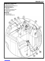
OPERATOR’S COMPARTMENT
EE Solution Flow Control Lever
FF Main Broom Raise/Lower (ON/OFF) Lever
GG Main Broom Adjust Knob
HH Hopper Safety Support Lever
II Control Panel
JJ Main Broom Overload Indicator Light
KK Emergency Battery Disconnect
LL Tilt Wheel Lever
MM Drive Pedal
NN Brake Pedal
OO Parking Brake Latch
PP Operator Seat Adjustment Lever

A-14 / ENGLISH
A-14 - FORM NO. 56041776 - CR 1100, CR 1200
PRE-OPERATIONAL CHECKLIST
Before Each Use:
* Inspect the machine for damage or oil and water leaks.
* Check the hydraulic oil level (27).
* Make sure the recovery tank is empty.
* Make sure the battery charger is not connected to the machine.
* Check battery charge condition.
In the Driver’s Seat:
* Be sure that you understand the operating controls and their functions.
* Adjust the seat to allow easy reach of all controls.
* Insert the Master Key and turn the Ignition Key Switch (CC) to the ON position. Check for proper operation of the Horn (B), Hour Meter (BB)
and Headlights (14). Turn the Ignition Key Switch (CC) OFF.
* Check the Parking Brake Latch (OO). The latch must hold its (locked parked) setting fi rmly with out easily being released.
(Report all defects immediately to service personnel).
Plan Your Cleaning in Advance:
* Presweep heavily littered areas for more effi cient operation.
* Arrange long runs with a minimum of stopping or starting.
* Allow 6 inches of broom path overlap to ensure complete coverage.
* Avoid making sharp turns, bumping into posts, or scraping the side of the machine.
MAIN BROOM
Several different main brooms are available for this machine. Contact your Nilfi sk dealer if you need help selecting the best broom for the surface
and litter that you will be sweeping. NOTE: Reference broom maintenance for installation steps.
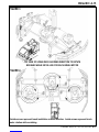
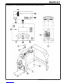
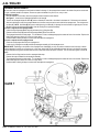
SCRUB BRUSH INSTALLATION
1 Make sure the Key Switch (CC) is off (O). See Figure 3. Remove side skirt assemblies for easier access. NOTE: Loosen large Black Knob
(A) at the front of each skirt mounting bracket, slide the skirt assembly forward and lift straight UP and off scrub deck.
2 To mount the brushes (or pad holders) align the lugs on the brush with the holes on the mounting plate and turn to lock in place according to
rotation directions shown in Figure 4.


A-16 / ENGLISH
A-16 - FORM NO. 56041776 - CR 1100, CR 1200
FILLING THE SOLUTION TANK
The solution tank fi ll (3) is located at the left rear corner of the machine and has a 75 gallon (284 liter) maximum capacity. Fill the tank with the proper dilution of cleaning
chemical mixed with water according to the manufacturer’s recommendations. If using a powdered chemical, mix it with water in a bucket before putting it into the
machine’s solution tank. NOTE: DO NOT fi ll the tank past the Maximum Level on the Water Level Gauge (24). NOTE: EDS machines can either be used conventionally
with detergent mixed in the tank or the EDS detergent dispensing system can be used. When using the EDS detergent dispensing do not mix detergent in the tank, plain
water should be used.
CAUTION!
Use only low-sudsing, non-fl ammable, non-caustic cleaning chemicals intended for machine application.
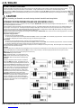
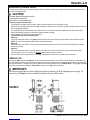
DETERGENT SYSTEM PREPARATION AND USE (EDS MODELS ONLY)
Fill the detergent cartridge with a maximum of 2.2 gallons (8.32 Liters) of detergent. SERVICE NOTE: Remove the detergent cartridge from the detergent box prior to
fi lling to avoid spilling detergent on the machine.
It is recommended that a separate cartridge be used for each detergent you plan to use. The detergent cartridges have a white decal on them so you can write the detergent name
on each cartridge to avoid mixing them up. The detergent cartridge has a Magnetic Slider (A) on one end that needs to be set to the proper dilution ratio according to the dilution
instructions on the manufacturer’s bottle. Slide the Magnet Slider (A) to the appropriate location on Detergent Dilution Ratio Decal (B). When installing a new cartridge, remove the
Cap (C) and place the cartridge in the detergent box. Install the Dry Break Cap (D) as shown.
The system should be purged of previous detergent when switching to a different detergent. SERVICE NOTE: Move machine over fl oor drain before purging because a small amount
of detergent will be dispensed in the process.
To Purge When Changing Chemicals:
1 Disconnect and remove the detergent cartridge.
2 Turn the Key Switch (CC) ON and press the Detergent ON/OFF Switch (RR) for at least 2 seconds. NOTE: Once activated the purge process takes 10 seconds. See illustration
on next page for Detergent System indicators. Normally one purge cycle is adequate to purge the system.
To Purge Weekly:
1 Disconnect and remove the detergent cartridge. Install and connect a Cartridge fi lled with clean water
2 Turn the Key Switch (CC) ON and press the Detergent ON/OFF Switch (RR) for at least 2 seconds. NOTE: Once activated the purge process takes 10 seconds. See illustration
on next page for Detergent System indicators. Normally one purge cycle is adequate to purge the system.
The Detergent Box (E) has a Detergent Level Viewing Slot (F) for keeping track of how much detergent is remaining in the cartridge. When the detergent level is nearing the bottom
of this slot it is time to refi ll or replace the cartridge.
General Use:
The detergent (EDS) system is enabled when the Key Switch (CC) is turned on and reverts to the last state (Chem On or Chem Off) it was in prior to the last power down. The current
Solution Flow Rate (VV) and the last used Detergent Ratio (WW) (if in “Chem On” state) are displayed. The Status LED (YY) indicates the status of the system as follows:
GREEN: Solution not low and chemical pump ON (pumping solution and chemical)
BLINKING GREEN: Purge has been activated
LED OFF: Solution fl ow position = 0 or solution solenoid is OFF
ORANGE: Solution ON and Chemical OFF (pumping solution only)
BLINKING RED: Solution low and chemical pump ON (pumping
solution only)
No detergent is dispensed until the scrub system is activated and
the Drive Pedal (MM) pushed forward. The detergent ratio can be
varied by subsequently pressing the Detergent Ratio Increment and
Decrement Switches (SS & TT). The detergent fl ow rate increases or
decreases with the solution fl ow rate but the detergent ratio remains
the same unless changed. During scrubbing, the detergent system
can be turned off at any time by pressing the Detergent ON/OFF
Switch (RR) to allow scrubbing with water only. On EDS models
the solution fl ow rate (40%-100%) is electronically controlled and is
displayed (VV) on the EDS display panel as shown below.
SERVICE NOTE: Follow the “To Purge Weekly” instructions above
if the machine is going to be stored for an extended period of time
or if you plan to discontinue use of the detergent (EDS) system.
The Display Panel (UU) will display an Error Code “E1” (XX) in the
lower left corner if the magnetic slider circuit board (ZZ) becomes
disconnected or malfunctions.


A-18 / ENGLISH
A-18 - FORM NO. 56041776 - CR 1100, CR 1200
OPERATING THE MACHINE
This is a rider-type automatic fl oor sweeping and scrubbing machine. It is designed to sweep up debris, lay down cleaning solution, scrub the
fl oor, and vacuum dry all in one pass. The sweeping and scrubbing operations can also be performed separately.
The controls were designed with one touch operation in mind. For single pass scrubbing the user can simply depress one switch and all scrub
functions on the machine will be ready to go. For sweeping, the operator can simply lower the main broom and all sweeping functions will be ready
to go.
Use the Drive Pedal (MM) to control the speed of the machine. The speed of the machine will increase as the pedal is pushed closer to the fl oor.
Do not press the Drive Pedal (MM) until the Main Power Switch (CC) has been turned on.
SWEEPING
Follow the instructions in preparing the machine for use section of this manual.
1 While seated on the machine, adjust the seat and steering wheel to a comfortable operating position using the adjustment controls (PP) and
(LL).
2 Release the Parking Brake (OO). To transport the machine to the work area, apply even pressure with your foot on the front of the Drive
Pedal (MM) to go forward or the rear of the pedal for reverse. Vary the pressure on the foot pedal to obtain the desired speed.
3 Push the Lower Hopper Switch (Z) to make sure the hopper is seated properly.
4 Move the Main Broom Lever (FF) to the SWEEP (middle notch) position to lower and enable the main broom. NOTE: The dump door opens
automatically when the main broom (FF) is lowered and closes when the broom is raised.
Use the FULL FLOAT (last notch forward) position only when sweeping extremely rough or uneven fl oors. Use at other times will only
increase broom wear.
5 When sweeping dry fl oors, push the Dust Control Switch (T) to turn ON the dust control system.
When sweeping fl oors with puddles, push the Dust Control Switch (T) to turn OFF the dust control system before the machine enters a
puddle. Turn the dust control system back ON when the machine is back on completely dry fl oor.
When sweeping wet fl oors, keep the Dust Control Switch (T) OFF at all times.
6 Lower the Side Broom(s) (P) when sweeping along walls or curbs. Raise the Side Broom(s) (U) when sweeping in open areas. Push and
hold the Side Broom ON/DOWN Switch (P) to lower and start the side broom motor(s). NOTE: Hold the switch until the side broom(s)
have lowered to the desired level. Side broom sweeping pattern is adjusted by pushing switches (P & U) until the desired amount of down
pressure is achieved. NOTE: If the side broom(s) were not raised and turned OFF after last use, they will automatically lower and turn ON
when the main broom is lowered and starts.
7 Drive the machine straight forward at a quick walking speed. Drive the machine slower when sweeping large amounts of dust or debris or
when safe operation dictates slower speeds. Overlap passes 6 inches (15 cm).
8 If dust comes out of the broom housing while sweeping, the Dust Control Filter (17) may be clogged. Push the Shaker Switch (S) to clean the
dust control fi lter. The dust control system (T) will automatically turn OFF while the shaker is running and turn ON after the shaker turns OFF
(the shaker runs for 20 seconds).
9 Check behind the machine occasionally to make sure that the machine is picking up debris. Dirt left behind in the path of the machine usually
indicates that the machine is moving too fast, the broom needs to be adjusted, or the hopper is full.
EMPTYING THE HOPPER
WARNING!
Make sure the Hopper Safety Support (HH) is in place whenever attempting to do any maintenance work under or near the raised
hopper. The Hopper Safety Support (HH) holds the hopper in the raised position to allow work to be performed under the hopper.
NEVER rely on the machine’s hydraulic components to safely support the hopper.
1 Push the Shaker Switch (S) to remove excess dirt from the dust control fi lter. SERVICE NOTE: For best shaker performance always run
the shaker with the hopper fully down.
2 Drive the machine close to a large trash receptacle and hold the Raise Hopper Switch (AA) until the hopper is all the way up. NOTE: The
dump door automatically closes when switch (AA) is pushed. You regain control of the dump door as soon as the hopper begins to raise so
you can dump at any height if necessary.
3 Move the machine forward until the hopper is over the receptacle, then press the Open Dump Door Switch (V) to open the dump door and
empty the hopper.
4 Check the back of the hopper and the front of the broom housing. Use a broom, if necessary, to remove litter from these areas. The back of
the hopper must seal tightly against the front of the broom housing for proper operation.
5 Back the machine away from the receptacle until the hopper will clear it, and then lower the hopper (Z). NOTE: The dump door will
automatically open when sweep function is resumed.

ENGLISH / A-19
FORM NO. 56041776 - CR 1100, CR 1200 - A-19
SCRUBBING
Follow the instructions in preparing the machine for use section of this manual.
1 While seated on the machine, adjust the seat and steering wheel to a comfortable operating position using the adjustment controls (PP) and (LL).
2 Release the Parking Brake (OO). To transport the machine to the work area, apply even pressure with your foot on the front of the Drive Pedal (MM) to go
forward or the rear of the pedal for reverse. Vary the pressure on the foot pedal to obtain the desired speed.
3 Adjust the Solution Flow Control Lever (EE) to about 1/4 to 1/3 (40%-100% on EDS) open position. The adjustment can be changed to allow variable
solution fl ow for different types of fl oors to be scrubbed. Example: A rough or absorbent fl oor surface, such as unfi nished concrete will require more solution
than a smooth fi nished fl oor.
4 Press the Solution Switch (K) and hold for 5 seconds. This is done to pre-wet the fl oor. Note: This will help prevent scarring of the fl oor surface when
starting to scrub with dry brushes.
5 Press the Scrub Pressure Decrease Switch (H) or the Scrub Pressure Increase Switch (I) to activate the scrub system.
6 When the Scrub Pressure Decrease Switch (H) or the Scrub Pressure Increase Switch (I) are selected, the brushes and squeegee are automatically lowered
to the fl oor. The machine’s scrub brush rotation, solution system fl ow, detergent fl ow(EDS only) and vacuum starts when the Drive Pedal (MM) is activated.
Note: When operating the machine in reverse, only the brushes will rotate, the solution and detergent(EDS only) is automatically shut off and the squeegee
raises.
7 Begin scrubbing by driving the machine forward in a straight line at a normal walking speed and overlap each path by 6 inches (15 cm). Adjust the machine
speed and solution fl ow according to the condition of the fl oor.
CAUTION!
To avoid damaging the fl oor, keep the machine moving while the brushes are turning.
8 When scrubbing, check behind the machine occasionally to see that all of the waste water is being picked up. If there is water trailing the machine, you may
be dispensing too much solution, the recovery tank may be full, or the squeegee tool may require adjustment.
9 For extremely dirty fl oors, a one-pass scrubbing operation may not be satisfactory and a “double-scrub” operation may be required. This operation is the
same as a one-pass scrubbing except on the fi rst pass the squeegee is in the up position (press the Vacuum Switch (N) to raise the squeegee). This
allows the cleaning solution to remain on the fl oor to work longer. The fi nal pass is made over the same area, with the squeegee lowered to pick up the
accumulated solution.
10 The recovery tank has an automatic vacuum shut-off to prevent solution from entering the vacuum system when the recovery tank is full. When the vacuum
shut-off is activated, the control system will shut down the vacuum system. The Recovery Tank FULL Indicator (M) will light. When the vacuum shut-off is
activated, the recovery tank must be emptied.
11 When the operator wants to stop scrubbing or the recovery tank is full, press the Scrub System OFF Switch (O) once. This will automatically stop the scrub
brushes, solution fl ow, detergent fl ow(EDS only) and the scrub deck will raise UP. NOTE: the vacuum/squeegee system will not be turned off when the
switch is only pressed once. This is to allow any remaining water to be picked up without turning the vacuum back on. Press the switch a second time and
the squeegee will raise and the vacuum will stop after a 10 second delay.
12 See the instructions below for emptying the recovery tank. Refi ll the solution tank and continue scrubbing.
EMPTYING THE RECOVERY TANK
1 Drive the machine to a designated waste water “DISPOSAL SITE”.
2 To empty, pull the Drain Hose (5) from its storage area, hold the end of the hose above the water level in the tank to avoid sudden, uncontrolled fl ow of waste
water and open the cap. NOTE: You can also pinch the fl exible end of the hose to control waste water fl ow as shown below.
3 Flush the tank and drain hose with clean water.
4 Reclose the cap and return the hose to its storage area.
SERVICE NOTE: The recovery tank can be tipped out to the side for cleaning after emptying. Release the Latch (6) at the front of the tank and then pull out on
the tank with grip (26) until the tank reaches the end of its tether. Remove the recovery tank lid for easier cleaning. The recovery tank can also be removed for
cleaning. You will need to disconnect the wire harness and tether fi rst and then use at least 2 people to lift off.
SERVICE NOTE: Refer to the service manual for detailed functional descriptions of all controls and optional programmability.

A-20 / ENGLISH
A-20 - FORM NO. 56041776 - CR 1100, CR 1200
AFTER USE
1 Raise the squeegee, the scrub brushes, and the brooms.
2 Shake the dust control fi lter and empty the hopper.
3 Drain and fl ush the recovery tank.
4 Tip the recovery tank out and check the squeegee hose elbow below the tank for debris. DO NOT run water down the recovery tank vacuum
tubes, this may cause damage to the vacuum motors.
5 Remove and clean the squeegee tool.
6 Remove and clean the scrub brushes. Rotate the scrub brushes.
7 Wipe the machine with a damp cloth.
8 Perform all required maintenance before storage.
9 Move the machine to a clean, dry storage area.
10 Store the machine with the brooms, the squeegee and the scrub brushes in the UP position, and the tank covers open so that the tanks can
air out.
REPORT ANY DEFECT OR MALFUNCTION NOTED DURING OPERATION TO AUTHORIZED SERVICE OR MAINTENANCE PERSONNEL.
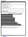
MAINTENANCE SCHEDULE
Keep the machine in top condition by following the maintenance schedule closely. Maintenance intervals given are for average operating
conditions. Machines used in severe environments may require service more often.
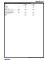
25 150 300 Yearly
MAINTENANCE ITEM Daily Hours Hours Hours (1,000hrs)
Charge Battery X
Drain / Check / Clean Tanks & Hoses X
Check / Clean / Rotate Scrub Brushes & Pads X
Check / Clean / Adjust Squeegee X
*Check / Clean Vacuum Motor Inlet Screen Cap X
Clean Solution Filter (32) X
Check Battery Cell Water Level(s) X
Check Foot/ Parking Brake For Wear & Adjustment X
Inspect Broom Housing Skirts X
Check Hydraulic Fluid Level X
Check / Clean Hopper Dust Control Filter Using Method “A” X
Inspect Scrub Deck Skirts X
Main Broom Maintenance X
Side Broom Maintenance X
Purge Detergent System (EDS only) X
** Lubrication X
Inspect Main Broom Upper & Lower Belts X
Check / Clean Hopper Dust Control Filter Using Method “B” X
Check / Clean Hopper Dust Control Filter Using Method “C” X
Replace Hydraulic Oil & Filter X
*** Check Carbon Brushes X
Have Nilfi sk service center inspect the wheel drive gearbox X
* DO NOT run water down the vacuum tube in the recovery tank this will damage the vacuum motors. Vacuum tube is on left side of tank with
screen cap.
** If the machine is being used in a very dusty or wet environment the lubrication should be performed once per week.
*** Have your Nilfi sk Dealer check the carbon motor brushes once a year or after 300 operating hours.
NOTE: Refer to the Service Manual for more detail on maintenance and service repairs.
La page charge ...
La page charge ...
La page charge ...
La page charge ...
La page charge ...
La page charge ...
La page charge ...
La page charge ...
La page charge ...
La page charge ...
La page charge ...
La page charge ...
-
 1
1
-
 2
2
-
 3
3
-
 4
4
-
 5
5
-
 6
6
-
 7
7
-
 8
8
-
 9
9
-
 10
10
-
 11
11
-
 12
12
-
 13
13
-
 14
14
-
 15
15
-
 16
16
-
 17
17
-
 18
18
-
 19
19
-
 20
20
-
 21
21
-
 22
22
-
 23
23
-
 24
24
-
 25
25
-
 26
26
-
 27
27
-
 28
28
-
 29
29
-
 30
30
-
 31
31
-
 32
32


Nilfisk-Advance CR 1100 Instructions For Use Manual
- Catégorie
- Machine à plancher
- Taper
- Instructions For Use Manual
- Ce manuel convient également à
dans d''autres langues
- English: Nilfisk-Advance CR 1100
Documents connexes
-
Nilfisk-Advance Hydro-Retriever 3800 Instructions For Use Manual
-
Nilfisk-Advance SC6000 34D Le manuel du propriétaire
-
-
Nilfisk-Advance 56212260 Manuel utilisateur
-
Nilfisk-Advance America UHR 70-1700 Manuel utilisateur
-
Autres documents
-
Nilfisk ES4000 Le manuel du propriétaire
-
-
Nilfisk-Advance America BRX 700 Series Manuel utilisateur
-
Nilfisk Terra 28B Manuel utilisateur
-
-
-
Nilfisk-ALTO SR 1450 B-D Manuel utilisateur
-
-
 Nilfisk-Advance America SR 1700D 2W D Manuel utilisateur
-
